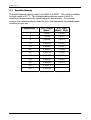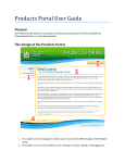
1
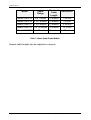
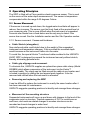
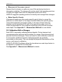
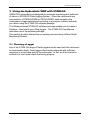
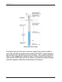
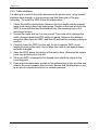
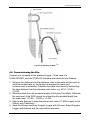
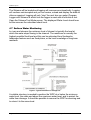
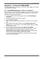
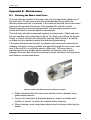
Hydrostatic Water Depth Probe Model 6542C Installation Guide Installation Guide Pub#6272 Revision C January 2008 Copyright Notice Copyright © UNIDATA Pty Ltd 1998 – 2008. All rights reserved. No part of this publication may be reproduced, transmitted, transcribed, stored in a retrieval system, or translated into any language or computer language, in any form or by any means, electronic, mechanical, magnetic, optical, chemical, manual or otherwise, without prior written permission of UNIDATA Pty Ltd, 40 Ladner Street, O’Connor, Western Australia, 6163, Australia. Disclaimer Unidata Pty Ltd reserves the right to revise this document for any reason, including but not limited to reasons relating to conformity with relevant international and national standards, application of advances in technology, the commercial availability of products or changing customer demands. Whilst every endeavour has been made to ensure the accuracy of this material, Unidata does not assume responsibility for any errors nor for any consequences arising from any errors in this publication. Printed in Australia Hydrostatic Water Depth Probe Table of Contents 1 INTRODUCTION...................................................................................................................................................4 1.1 1.2 1.3 2 FUNCTIONAL OVERVIEW ..................................................................................................................................4 FEATURES .......................................................................................................................................................5 MODELS ..........................................................................................................................................................5 OPERATING PRINCIPLES .................................................................................................................................7 2.1 SENSOR MOVEMENT........................................................................................................................................7 2.1.2 Sensor movement: Causes and Avoidance .......................................................................................7 2.2 CALIBRATION DRIFT OR CHANGES ...................................................................................................................8 3 USING THE HYDROSTATIC WDP WITH STARLOG ......................................................................................9 3.1 CHOOSING A LOGGER ......................................................................................................................................9 3.2 NOTES ON A WATER DEPTH MONITORING SCHEME USING STARLOG V3 SOFTWARE ..................................10 3.2.1 Adding an Instrument ..........................................................................................................................10 3.2.2 What to Log..........................................................................................................................................10 3.3 NOTES ON A WATER DEPTH MONITORING SCHEME USING STARLOG V4 SOFTWARE ..................................12 3.2.2 Adding an Instrument ..........................................................................................................................12 3.3.2 What to Log..........................................................................................................................................13 4 INSTALLATION..................................................................................................................................................14 4.1 INSTALLATION PLANNING................................................................................................................................14 4.2 DESIGNING THE INSTALLATION .......................................................................................................................14 4.2.2 Site Requirements...............................................................................................................................14 4.2.2 Instrument Requirements....................................................................................................................15 4.3 INSTALLATION ISSUES ....................................................................................................................................15 4.3.2 Housing the Instrument .......................................................................................................................15 4.3.2 Selecting the Cable Length.................................................................................................................16 4.3.2 Drying Tube and Desiccant.................................................................................................................16 4.4 GROUNDWATER MONITORING........................................................................................................................16 4.4.2 Groundwater Site Design Issues ........................................................................................................16 4.4.2 The Groundwater Measuring Structure..............................................................................................17 4.4.2 The Reference Mark............................................................................................................................17 4.5 INSTALLING THE INSTRUMENT ........................................................................................................................19 4.5.2 Cable Connections ..............................................................................................................................19 4.5.2 Cable Installation .................................................................................................................................20 4.6 COMMISSIONING THE SITE .............................................................................................................................21 4.7 SURFACE WATER MONITORING .....................................................................................................................22 4.8 WATER LEVEL CHECK FACILITIES ..................................................................................................................23 5 SPECIFICATIONS..............................................................................................................................................24 APPENDIX A – TESTING WITH STARLOGGER ...................................................................................................25 A.1 USING STARLOG SOFTWARE - VERSION 3 OR VERSION 4 ...........................................................................25 APPENDIX B - MAINTENANCE ...............................................................................................................................26 B.1 CLEANING THE WATER INLET PORTS .............................................................................................................26 B.2 SERVICING THE DESICCANT SYSTEM .............................................................................................................27 B.3 SITE MAINTENANCE .......................................................................................................................................27 B.3.1 Overview ..............................................................................................................................................27 B.3.2 Regular Maintenance ..........................................................................................................................28 B.3.3 Annual Maintenance............................................................................................................................28 APPENDIX C - MEASUREMENT METHOD............................................................................................................29 C.1 SPECIFIC GRAVITY .........................................................................................................................................30 6542C Hydrostatic Water Depth Probe – Installation Guide Page 3 of 30 UNIDATA Pty Ltd 1 Introduction The Hydrostatic Water Depth Probe (UNIDATA Model 6542C), provides accurate long term measurement of water depth from 0 to 20 metres and water temperature from -10o C to 50o C. It is fully sealed, factory calibrated (to standard ranges) and temperature compensated. The Water Depth Probe (WDP) is designed for permanent submersion in water and will measure water depth. The probe is ideal for monitoring drainage, bore depth and river height. It can also be used to measure water with dissolved solids (i.e. brine) and other liquids provided consideration is given to the following factors: 1. Density of the liquid under measurement, 2. Relationships between changing temperature and changing density of the liquid under measurement, and 3. Effect of the liquid under measurement on the stainless steel/ delrin housing and cable. These factors are discussed further in Appendix C. The service life of the WDP is indefinite provided it is not subjected to mishandling. The instrument does not require recalibration unless it is disassembled or damaged. Like all pressure instruments, the sensor calibration may change if the sensor is buried or exposed to severe chemical or biological fouling. Cleaning the sensor will normally restore the original calibration. Regular site checks to detect and fix any such changes will improve the data quality. This manual covers preparation, installation, operation and maintenance of the instrument. It also includes information on data management. Contact UNIDATA for further information or assistance. 1.1 Functional Overview The WDP uses a stainless steel pressure sensor to determine the water depth. Any potential errors introduced by this method have been minimised by the instrument design. A vent tube inside the connection cable removes the effects of atmospheric pressure on the measured water pressure, which can vary by 10kPa (100hPa or 1m head of water). The pressure is used to calculate the distance between the sensor and the water surface. This is reported as depth. Page 4 of 30 6542C Hydrostatic Water Depth Probe – Installation Guide Hydrostatic Water Depth Probe When installed in wells and bores, the special cable moulded to the instrument is designed to suspend the WDP. This cable is Kevlar™ reinforced, has a polyurethane jacket and can be mounted using an optional adjustable suspension link. For surface water monitoring, the instrument can be inserted into a vertical or sloping duct fixed to a structure or the stream bank. 1.2 Features Wide Application The WDP is designed to be used to monitor water level in tidal estuaries, streams, lakes, reservoirs, drains, wells, bore holes and other water bodies where it can be located underwater and below the minimum level to be measured. The WDP measures depth to the precision and accuracy specified in Table 1 and has the endurance for long-term monitoring projects. • Easy to Use The instrument has been designed for ease of use. Installation involves lowering the instrument to the required depth and fixing it in position. The instrument is tested and calibrated at the factory and is fully operational on dispatch. When connected to a STARLOGGER, no complex set-up routines, maintenance or calibration is required. Durable and Environmentally Safe Chemically inert materials are used for all instrument parts in contact with water. These materials will not contaminate natural waters. All instrument materials have been selected for durability and the housing and cable have been designed to withstand arduous physical conditions. The housing is made from marine grade stainless steel. The cable and moulding are made of polyurethane specially formulated for durability in underwater applications. The pressure sensor is sealed behind a stainless steel membrane. 1.3 Models The WDP is available in 1m, 2m, 5m, 10m, and 20m ranges. The model numbers are: 6542 Hydrostatic Water Depth Probe – Installation Guide Page 5 of 30 UNIDATA Pty Ltd Resolution 0 to 1 metre Standard Cable Length 15 metres Model 6542C/B 0 to 2 metres 15 metres 2.5 mm Model 6542C/C 0 to 5 metres 15 metres 6.25 mm Model 6542C/D 0 to 10 metres 15 metres 12.5 mm Model 6542C/E 0 to 20 metres 25 metres 25 mm Model Depth Range Model 6542C/A 1.25 mm Table 1: Water Depth Probe Models Special cable lengths can be supplied on request. Page 6 of 30 6542C Hydrostatic Water Depth Probe – Installation Guide Hydrostatic Water Depth Probe 2 Operating Principles The WDP is fitted with a Piezo-resistive electric pressure sensor. This is used as the source of the water depth measurements. The sensor is temperature compensated within the range 0-50 degrees Celsius. 2.1 Sensor Movement If the sensor is moved up and down, the logged water level data will appear to reduce, then increase. The sensor must be firmly fixed at the required level at your measuring site. This is more difficult when the instrument is suspended. Accurate site checks from a fixed datum are the only way to detect if the sensor has moved. See the Installation section and the Site Operation section. 2.1.2 Sensor movement: Causes and Avoidance Cable Stretch (elongation) Non-reinforced cable could stretch due to the weight of the suspended instrument and temperature changes. If this occurred the recorded depth would increase as the instrument settles into the water. To avoid this, the special Kevlar™ reinforced cable moulded to the UNIDATA 6542C WDP is designed to suspend the instrument securely without stretch, thereby eliminating potential error. Cable grip slippage and movement To eliminate this, UNIDATA supplies an optional two-piece cable clamp (Model 8008BM) which allows suspension of the instrument via the Kevlar™ reinforced cable. The clamp can be fitted around the cable at any location and is locked in position by sliding the two tapered parts together. It can be removed and refitted when the instrument is relocated. Removing and replacing the WDP It can be difficult to replace the instrument in exactly the same location after it has been removed for maintenance. UNIDATA suggests operating practices to identify and manage these changes. Movement of the mounting structure Suspended instruments will move up and down with changes to the level of the suspension point or structure. Thermal expansion of PVC or metal bores or well liners, and moisture-related changes to wooden structures can be recorded as diurnal changes in water level. UNIDATA suggests operating practices to identify and manage these changes. 6542 Hydrostatic Water Depth Probe – Installation Guide Page 7 of 30 UNIDATA Pty Ltd Movement of the sensor mount Sensors fixed in streams or wells can move if the anchoring structure is damaged or subsides. The change will only be noted if site operating practices compare the logged value with an independent water level check. UNIDATA suggests operating practices to identify and manage these changes. Water Specific Gravity All pressure transducers use a water-specific gravity factor to convert the pressure to a water depth. In the range of natural waters this specific gravity varies with temperature and water quality. In the case of fresh water the variation can be more than 0.5% and, in the case of sea water, up to 3%. Unless compensated for, this introduces significant errors into the recorded water depth. See Appendix C – Measurement Method for more details. 2.2 Calibration Drift or Changes Each WDP is accurately calibrated before dispatch. During transport and commissioning the instrument will be subject to a range of environmental and physical shocks and changes. These can result in minor calibration variances. In some water conditions mineral or biological growth can gradually accumulate on the sensor. This can change the physical characteristics of the sensor, and hence its calibration. UNIDATA STARLOG software allows the transducer zero and slope factors to be adjusted, to rescale the recorded data. See Appendix C – Measurement Method for details. Page 8 of 30 6542C Hydrostatic Water Depth Probe – Installation Guide Hydrostatic Water Depth Probe 3 Using the Hydrostatic WDP with STARLOG UNIDATA's instruments are designed for automatic monitoring and collection of data in a STARLOG Data Logging System. When the instruments are connected to a STARLOGGER or PROLOGGER, data sensed by the instruments is logged and stored according to a program (called a scheme) you define using the STARLOG software package. The Windows-based STARLOG software package enables you to create a Scheme – then load it into a Data Logger. The STARLOG User Manual describes use of the software package. This section provides information on creating and executing a Water Depth Monitoring Scheme. 3.1 Choosing a Logger Any of the STARLOG range of Data Loggers can be used with this instrument to record water depth. Each logger offers analog channels with sufficient resolution to record data sent by the instrument. In fact, an 8-bit channel is sufficient for most water depth monitoring projects. 6542 Hydrostatic Water Depth Probe – Installation Guide Page 9 of 30 UNIDATA Pty Ltd 3.2 Notes on a Water Depth Monitoring Scheme using STARLOG V3 Software This section describes the attributes of the probe and suggests how data gathered may be used. 3.2.1 Adding an Instrument To create a Water Depth Monitoring Scheme, first select a Probe from the Instrument List to add it to the Scheme. If the model you have does not appear in this list, you will need to add it (use the Instrument Editor in Version 3 Software). Once you have added the instrument to the Scheme, check to see which channel is allocated, scaling factors, format of data shown in reports, etc. The default settings are: Figure 1. Model 6542C Depth Transducer Details If you choose to use a channel other than the default as shown here, ensure that you make the connection to the correct terminal of the Field Termination Strip, if you are using that option or, the correct pin in the INPUT SIGNALS connector. 3.2.2 What to Log The logging options are as follows: • • • • The value read at the previous log interval (RAW) Maximum water depth calculated over the log interval (MAX) Minimum water depth calculated over the log interval (MIN), or The average of all (AVE) or some (ave) scans Page 10 of 30 6542C Hydrostatic Water Depth Probe – Installation Guide Hydrostatic Water Depth Probe Make the following selections in the Log Buffer window: Figure 2.Log Buffer Selections For an example of use: With a time-based scheme you may want to log the average value of all scans and also the maximum during each log period. Averaging data has the effect of smoothing out minor variations. It is a useful way of eliminating “spikes” caused by waves or ripples. Logging an average over a long period, say one hour, may de-sensitise the data. Using the sub-interval of say, one minute would log the average of the last one minute of data each hour. Select as many log actions as required, by checking the box in each required column on the line next to the instrument’s channel. 6542 Hydrostatic Water Depth Probe – Installation Guide Page 11 of 30 Hydrostatic Water Depth Probe 3.3 Notes on a Water Depth Monitoring Scheme using STARLOG V4 Software This section describes the attributes of the probe and suggests how gathered data may be used. 3.2.2 Adding an Instrument To create a Water Depth Monitoring Scheme, select a Probe from the Instrument List to add it to the Scheme. If the model you have does not appear in this list, you will need to add it (use the Instrument Editor in Version 4 Software library). Once you add the instrument to the Scheme, check to see which channel is allocated, scaling factors, format of data shown in reports, etc. The default settings are: Figure 3. Model 6542C Depth Transducer Details If you choose to use a channel other than the default as listed here, ensure that you make the connection to the correct terminal of the Field Termination Strip, if you are using that option or, the correct pin in the input in the INPUT SIGNALS connector. The new depth probes are no longer a 0-2550mV output instrument as the previous revisions were. We now have a 500mV positive voltage offset which is automatically configured in the software. Page 12 of 30 6542 Hydrostatic Water Depth Probe – Installation Guide Hydrostatic Water Depth Probe 3.3.2 What to Log The logging options are as follows: • • • • The value read at the previous log interval (RAW) Minimum water depth calculated over the log interval (MIN) Maximum water depth calculated over the log interval (MAX), or The average of all (AVG) or some (avg) scans Make the following selections in the Log Buffer window: Figure 4.Log Buffer Selections For an example of use: With a time-based scheme you may want to log the average value of all scans and also the maximum during each log period. Averaging data has the effect of smoothing out minor variations. It is a useful way of eliminating “spikes” caused by waves or ripples. Logging an average over a long period, say one hour, may de-sensitise the data. Using the sub-interval of say, one minute would log the average of the last one minute of data each hour. Select as many log actions as required by checking the box in each required column on the line next to the instrument’s channel. 6542 Hydrostatic Water Depth Probe – Installation Guide Page 13 of 30 UNIDATA Pty Ltd 4 Installation 4.1 Installation Planning The WDP can provide accurate and reliable water level data for long periods. However: • Project planning, • Site selection and design and, • Instrument installation and operation will determine the success of your data collection commitment. It is not possible to collect good data from an unsuitable or poorly designed site. At the planning stage, the general objectives of the project and the specific requirements of each site should be clearly defined. The sites can then be selected and designed to suit these objectives, the instruments selected to suit the sites and the operating strategies implemented to achieve the required data quality. As data collection progresses the results can be regularly reviewed and the sites and operating strategies modified as required to meet the objectives. A focus on regular data analysis and reporting of results will maintain the relevance of the project and achieve the maximum benefits. 4.2 Designing the Installation The following issues should be considered in the selection and design of sites. Specific issues relating to Groundwater and Surface Water sites are discussed in the following sections. 4.2.2 Site Requirements The following site requirements should be considered: • • • • • • The site should be suitable for measuring the required data range. It should be accessible for regular maintenance. There should be a safe working environment for staff. The measuring structure should be stable for the life of the project and must not move vertically with time. There should be a secure, dry, clean instrument housing for site accessories such as external power and telemetry. The water level within the measuring structure must be the same as the aquifer or water surface of interest, and follow the external changes. Page 14 of 30 6542 Hydrostatic Water Depth Probe – Installation Guide Hydrostatic Water Depth Probe 4.2.2 Instrument Requirements The following factors regarding the Water Depth Probe should be considered before installation: • • • • • • • • • The instrument range should span the full range of water level variations to be measured at the site. The WDP must be located at a fixed point below the minimum water level of interest. Removal and reinstallation of the WDP to the same position should be possible. The WDP cable “dry end” should be kept clean, dry and protected from damage or interference. Do not twist or crimp the cable. This cable contains a high quality small Teflon tube which vents the body of the Water Depth Probe. If this vent tube is twisted or crimped, errors in the data recorder will occur. The vent tube outlet needs to be open to atmosphere. This allows the sensor to reference water pressure to atmosphere pressure. In particularly humid environments a desiccant tube (6603DT) may be required to prevent blockage in the vent tube formed by precipitation. The overall length of the cable should not exceed 55 metres. Strong water currents should be avoided as these can lead to the Water Depth Probe “swinging” and producing inaccurate and oscillating data. If the Water Depth Probe is to be used in a high current area, use of a still well is recommended. Although the Water Depth Probe is of a robust design the ingress of mud and silt into the sensor water inlet ports can contribute to data errors. Immersion of the probe in mud or silt may result in data error. The WDP will not be damaged if it is out of water, or if its measuring range is exceeded (provided the vent-tube at the end of the cable does not go underwater). In the natural environment it is often the maximum and minimum values that are of the greatest interest. 4.3 Installation Issues 4.3.2 Housing the Instrument The WDP should be installed in a way that protects the instrument and cable from accidental damage, interference, vandalism or, deterioration caused by insect or animal attacks or by abrasion from continual water movement. Associated logging and power supply equipment should be located inside a weatherproof enclosure such as a UNIDATA Model 6701. The enclosure should not be completely sealed, as the vent tube needs to vent to the 6542 Hydrostatic Water Depth Probe – Installation Guide Page 15 of 30 UNIDATA Pty Ltd atmosphere. If the sealed lead acid battery is used, it too can vent gas during an overcharge condition. 4.3.2 Selecting the Cable Length Normally the instrument is suspended from its cable, using the optional clamp (Model 8008BM) with the cable end above ground level where it can be connected to your computer. This allows you to check the instrument while it is operating and recording the water level. You will need to order cable lengths to suit each site. 4.3.2 Drying Tube and Desiccant The WDP cable contains a vent tube to reference the pressure sensor to atmospheric pressure. It is very important to ensure that NO MOISTURE enters the vent tube. If the tube is blocked, erratic depth measurements may be recorded. The WDP may optionally be vented to atmosphere through a drying tube (Model 6603DT) containing silica gel desiccant. Do not locate the tube in an area subject to moisture or artificial pressure changes. Open the vent on the drying tube. Replace or regenerate the desiccant when it changes colour from blue to pink. See Appendix B - Maintenance for more information. 4.4 Groundwater Monitoring 4.4.2 Groundwater Site Design Issues It can be difficult to estimate the possible range of ground water level variation in a bore or well. This will be related to the natural topography, geology, rainfall and water use. There may be several layers of groundwater at different levels, and each of these aquifers can change in different ways. In bores close to high volume pumping, large and unpredictable level changes can occur. The design and construction of a bore will influence the standing water level. In larger bores the casing is normally sealed at the bottom and slotted or screened at a particular depth to allow water entry from the aquifer of interest. Leakage down the casing from surface runoff or higher aquifers may affect the standing water level within the bore. In a natural region with alluvial soils such as a river valley, the shallow water table frequently underlies the landscape as a flat plane with a gentle slope toward an outlet in a stream or the ocean. The level will change slowly and the range of changes will be similar across the region with minor variations due to local water consumption. If you are not sure of the expected range, seek information from local groundwater users or experts. Review data from any monitoring at nearby sites. Select an instrument range that exceeds the expected water level Page 16 of 30 6542 Hydrostatic Water Depth Probe – Installation Guide Hydrostatic Water Depth Probe variation. Position the instrument well below the minimum expected water level. You may need to vary the instrument position as the seasons change. 4.4.2 The Groundwater Measuring Structure The following section describes the structure for groundwater measuring: • • • • • • The bore screens or inlets that allow water entry should be functional. The level of the lowest inlet will determine the minimum relevant recording level. Surface run off and leakage down the outside of the casing should be prevented. The inside diameter of the bore must be clear and smooth and at least 30mm diameter. If there are obstructions with the bore or well that might trap or jam the WDP, consider installing a 30mm PVC pipe insert as a mounting tube for the WDP. A permanent mounting point is required to suspend the instrument. A Reference Mark should be installed at the top of the well or bore casing, vertically over the water surface. 4.4.2 The Reference Mark The WDP can be installed in any vertical bore or well. A permanent reference mark is required at the top. The reference mark is allocated a level. This may be from an assumed datum, eg. 100.000 metres Assumed Datum. This mark can also be surveyed to a project datum eg. 40.310m. A common datum is essential if you wish to compare the water levels at different sites within a project. The vertical distance between this mark and the water surface is measured at each site inspection. At installation the level of the water surface can be calculated and the WDP set to record this level. At all future checks the measured water surface level can be checked against the recorded level. 6542 Hydrostatic Water Depth Probe – Installation Guide Page 17 of 30 UNIDATA Pty Ltd Figure5. WDP Reference Mark The level of the top of the bore or well can change if the structure settles or rises. This will affect the water level recorded by the WDP. A check survey of the reference mark should be carried out annually. Use a stable local Bench Mark or other independent reference mark to confirm that the site reference mark (and the WDP anchor point) are stable. Any significant verified changes should be applied to adjust the recorded data for the period. Page 18 of 30 6542 Hydrostatic Water Depth Probe – Installation Guide Hydrostatic Water Depth Probe 4.5 Installing the Instrument 4.5.2 Cable Connections The Water Depth Probe has four wires emerging from the cable as well as the vent tube for the probe housing. Connect these wires to either a Field Termination Strip (FTS) or directly to the Data Logger. The use of an FTS eases the task of connecting and disconnecting devices to the Data Logger. The cable connections are as follows: Probe STARLOGGER PROLOGGER Colour Function Pin Term. Pin Term. Brown +5VDC power supply 13 15 18 55 White Depth signal 1 39 20 39 Green Signal Ground 14 41 1 40 Blue Power Gnd 23 14 28 17 Table 2: Cable Connections The STARLOGGER offers eight analog channel inputs located on pins 1 to 8 (a0 to a7). Any of these can be used with a Water Depth Probe provided that the correct channel number is designated when using the STARLOG Software. 6542 Hydrostatic Water Depth Probe – Installation Guide Page 19 of 30 UNIDATA Pty Ltd 4.5.2 Cable Installation If a cable grip is used it should be attached to the anchor point, using a small stainless steel shackle, or the mounting loop that forms part of the grip assembly. To install the WDP follow the steps below: 1. Check the well for obstructions. Measure the bore depth and the present water level using a bore hole tape gauge. Decide on the level at which the WDP is to be installed and the distance from the mounting loop to the instrument location. 2. Unwind the cable and lay it on the ground. Take care not to damage the cable. Always handle the WDP cable coil gently. Measure the distance along the cable from the WDP, and then fit and lock the mounting clamp in position. 3. Carefully lower the WDP into the well. As you lower the WDP, avoid twisting or kinking the cable. Do not allow the cable to rub against sharp surfaces or angles. 4. Keep the WDP above the bottom of the well or bore, otherwise the sensor ports may be blocked by fine silt. 5. When the WDP is lowered to the desired level attach the clamp to the mounting point. 6. Ensure that the desiccator crystals in the optional drying tube are blue and remove the seal to expose the vent hole. Ensure that the desiccator is not in an area of excessive moisture or variable pressure. Page 20 of 30 6542 Hydrostatic Water Depth Probe – Installation Guide Hydrostatic Water Depth Probe Figure6.: Suspending the WDP 4.6 Commissioning the Site Connect your computer to the attached Logger. In the case of a STARLOGGER, start the STARLOG Software and select the site Scheme. 1. Measure the distance from the reference mark to the water surface with an electrical contact tape or, similar device designed for water level measurement in boreholes. Calculate the water level check by subtracting the tape distance from the reference mark value. e.g. 40.31 - 9.045 = 31.265. 2. Read the depth from the computer display in Scheme Test Mode. Calculate the zero level of the WDP sensor by subtracting the recorded depth from the water level. (31.265 - 13.829) = 17.436. 3. Edit the site Scheme to enter the sensor zero value (17.436) to apply to the Water Level Transducer. 4. Save the Scheme and then Program Logger with Scheme. Select Program Logger with Scheme and the reset will be automatic. 6542 Hydrostatic Water Depth Probe – Installation Guide Page 21 of 30 UNIDATA Pty Ltd The Scheme will be loaded and logging will commence automatically. Logging will continue uninterrupted and you can review, unload and display the data as often as required. Logging will only “stop” the next time you select Program Logger with Scheme at which time the logger is reset and all old data is lost. Open the Scheme Test Mode screen. The displayed Water Level should now be the same as the calculated check level. 4.7 Surface Water Monitoring In rivers and streams the minimum level of interest is typically the level at which the water stops flowing in the channel. The maximum is normally the highest possible flood level and this can be estimated from floodmarks, landscape features such as flood plains, or the local knowledge of long-term residents. Figure7.: Typical Installation on a Bridge Pier A suitable structure is needed to position the WDP at or below the minimum water level, the cable end above the maximum water level, and to protect the cable from damage. It should be possible to remove the WDP for servicing and to return it to the same level. Page 22 of 30 6542 Hydrostatic Water Depth Probe – Installation Guide Hydrostatic Water Depth Probe A vertical tube can be used for an instrument mount. A steel pipe with a minimum diameter of 40mm can be attached vertically to a bridge pier, dam wall, or to the side of a tank. The bottom can be capped and drilled as a sieve to allow water into the tube and reduce the effects of velocity. The WDP can be lowered down the pipe to rest on the bottom. The top of the tube can be capped with a vented cap and should be locked if security is required. If there is surplus cable, other instruments, or a power supply at the site, you will need an instrument cabinet. 4.8 Water Level Check Facilities It is essential to provide suitable facilities to obtain a check water level at the site. For example: • • • If there is a bridge or other structure over the water surface, establish a reference mark and survey it to the project datum. Measure to the water surface to obtain a check reading. On sloping stream banks a range of staff gauges may be established and surveyed to the site datum. The water level check can then be read from these gauges. The gauges should be regularly checked and maintained, as some movement may occur. The water surface level may be surveyed or measured from reference points located up the stream bank. The same techniques are used to operate surface and groundwater sites. 6542 Hydrostatic Water Depth Probe – Installation Guide Page 23 of 30 UNIDATA Pty Ltd 5 Specifications Depth Overall accuracy: 0.5% FS for 1m,2m range; 0.25% FS for 5m,10m,20m ranges, over a range of 0 to 50 deg C Repeatability: 0.05% full scale. Operating temp.: -10° to 50°C Temp. coefficient: <0.02% full scale per °C. Operating range: 1, 2, 5, 10, and 20 metres of water. Long term stability: 0.2% full scale per year. Overload pressure: Two times full-scale range. Calibration will be affected only when this is exceeded. Burst pressure: Three times full-scale range. Settling time: Within sixty seconds of immersion. Pressure sensor: Stainless steel piezo-resistive silicon strain gauge (AIS 316L). Output and Input Signals Output Signal: Resolution: Overpressure: Connector: Cable: Material: Size: Weight: Power: Page 24 of 30 500mV to 2500mV DC analog (infinite) 2 times full scale Supplied unterminated 4core vented, 7.5 mm OD, blue polyurethane jacket, kevlar strength member Marine grade stainless steel (AISI 316). 27mm diameter, 113mm length 200g (excluding cable) +5V DC, < 8mA (from Unidata logger), +5 to 30V DC, < 8mA (external supply) 6542 Hydrostatic Water Depth Probe – Installation Guide Hydrostatic Water Depth Probe Appendix A – Testing with STARLOGGER The Water Depth Probe connected to a STARLOG Data Logger can be tested using STARLOG Software. A.1 Using STARLOG Software - Version 3 or Version 4 When connected to a STARLOG Data Logger, a computer running STARLOG Software can be used to interrogate a Water Depth Probe for real-time data reading and programming information. 1. Connect the Probe to the Data Logger (see section 4.5 Installing the Instrument). 2. Connect the STARLOGGER to the computer. 3. Start STARLOG Software. 4. Select the Water Depth Monitoring Scheme (or create one, if you haven’t yet). 5. If the Scheme has not been loaded, choose Program Logger with Scheme from the Control Panel. If the STARLOGGER already is loaded with the Scheme, then… 6. From the Schemes Control Panel, select Scheme Test Mode. 7. View the display to determine how the scheme is operating. The Test Window (upper window) displays scheme information from the STARLOGGER and its contents is updated every Scan. The Log Entry Window (lower window) displays what has been logged. You can also use Scheme Test Mode to create your own Test Screens (see the User Manual 6245). 6542 Hydrostatic Water Depth Probe – Installation Guide Page 25 of 30 UNIDATA Pty Ltd Appendix B - Maintenance B.1 Cleaning the Water Inlet Ports The inlet ports are located in the nose cone (cone-shaped black plastic tip) of the instrument. These ports lead to the small chamber above which the delicate pressure sensor is mounted. If the holes are blocked, the correct water pressure will not reach the sensor. If the chamber fills with silt or sand, biological growth or chemical contaminants, this may apply pressure to the sensor and result in incorrect depth measurements. The inlet holes should be inspected regularly and kept clean. Check and note the zero reading of the instrument in the air. An offset may indicate the sensor is dirty or fouled. Recheck the offset after cleaning. Make notes of all results, as these may be required to adjust the data during processing. If the water inlet ports are blocked, the plastic nose cone can be removed for cleaning. Unscrew it using a suitable tool inserted through the nose cone, such as a 2.5mm drill bit, or small hex wrench (Allen key). The nose cone is manufactured from a durable plastic material, but exercise care to avoid damage. Removal also allows the instrument sensor chamber to be inspected and cleaned, as described below: Figure8.: Cleaning the Water Inlet Ports and Sensor Chamber • Wash all material from the nose cone and the sensor chamber using gentle water pressure. • For dry silt or chemical or biological deposits, soak in a suitable mild solution or solvent, to soften the material before cleaning. • When cleaning, avoid using sharp objects and touching or distorting the sensor. Page 26 of 30 6542 Hydrostatic Water Depth Probe – Installation Guide Hydrostatic Water Depth Probe • For very persistent blockages, use a small soft brush to clean by hand. • Flush the ports and chamber with clean water after clearing. • Gently blow the sensor chamber and nose cone dry. • Screw the cone into place finger-tight, ensuring that it fits properly against the machined face of the sensor chamber. • Tighten gently with a suitable tool - applying only the minimum effort needed to secure. • Check and record the zero reading prior to deployment. B.2 Servicing the Desiccant System An atmospheric pressure vent tube is part of the cable. As the temperature changes at the site, air breathes in and out through this tube. Any obstruction such as a drop of water or a small insect can block the tube and cause significant errors in the recorded depth. The UNIDATA Model 6603DT desiccator plugs onto the end of the tube to filter and dry any air entering the tube. The desiccator assembly contains a filter pad, standard colour-indicating silica gel crystals and a breather cap. The assembly can be exchanged, or reconditioned on site. The crystals are blue when dry and turn pink as they absorb moisture. When crystals start to turn pink the desiccator is no longer effective. To recondition the assembly, remove the cap and pour the old crystals into a storage container. Refill the desiccant container with dry silica gel crystals. Replace the cap leaving it unscrewed ½ turn to allow it to breathe. When the cap is closed the vent tube is blocked and large water depth errors may be recorded. The used silica gel can be reconditioned many times by heating in an oven for 1 hour at 100°C or in a microwave on low, until the crystals turn blue. Place them in an airtight container to cool. Store them in airtight containers to avoid moisture absorption. B.3 Site Maintenance B.3.1 Overview All sites and instruments need regular maintenance. The instrument systems need a secure location, a reliable power supply and protection from interference and damage. The site also requires maintenance. The instrument can work well, yet record poor data if the sensor moves or is blocked, or the water level at the sensor is incorrect. 6542 Hydrostatic Water Depth Probe – Installation Guide Page 27 of 30 UNIDATA Pty Ltd B.3.2 Regular Maintenance At each site inspection your routine checks should detect any problems that are affecting the data, and these should be fixed. Keep all sites tidy and in good condition. Trim vegetation, maintain and paint structures and clean instrument cabinets. Check for accumulations of silt that may bury the instrument. B.3.3 Annual Maintenance An annual check of the site conditions should allow additional time to carry out a thorough check to detect and fix any changes or deterioration that may affect the site data in the future. Take the time to review the data from the past year. Look for trends that may indicate changes to the instrument calibration, sensor contamination or the stability of the instrument position. It may be desirable to modify the instrument location or change the way it is installed or housed, to prevent future problems. Page 28 of 30 6542 Hydrostatic Water Depth Probe – Installation Guide Hydrostatic Water Depth Probe Appendix C - Measurement Method The Water Depth Probe uses hydrostatic pressure exerted on a Piezo-resistive electric pressure sensor as the primary data source. Hydrostatic pressure is reliant on several factors: • • • • The Density of the liquid (D) = specific gravity (S.G.) The acceleration of gravity (g) The depth of the liquid (d) Atmospheric pressure at the top of the liquid (Atm) Absolute pressure at d mm = (g x D x d) + Atm However the vent tube cancels atmospheric pressure (Atm) so: Gauge pressure = g x D x d (kPa) The gauge pressure from the Water Depth Probe is sent as a 0 – 2.55 Vdc signal (1mm water resolution). Using the above formula and the raw data readings, measurements can be made for any liquid. The UNIDATA Water Depth Probes are calibrated in clean water (S.G. = 1.00) at room temperature. If the Probes are used in sea water (S.G. = 1.02) the accuracy of the readings using the default transducer scaling in the STARLOG software package (which assumes S.G. to be 1.00), will be affected by a factor of -2.5% (To overcome this, define NEW transducers and scale the transducers appropriately). E.g. a 10 metre depth probe in sea water should be scaled as follows: Fullscale a to b a=0 b=9.80 The Water Depth Probe is compensated for temperature effects on the sensor; however it is not compensated for density changes in water or other liquids caused by temperature change. This is significant only in water where large changes occur in the range of 20 to 60 °C. The table below shows density changes in this range. Note that the effect is not significant in normal use. Temperature °C 20 25 30 40 60 Density .99823 .99732 .99567 .99225 .9832 Table 3: Temperature and Density Values 6542 Hydrostatic Water Depth Probe – Installation Guide Page 29 of 30 UNIDATA Pty Ltd C.1 Specific Gravity The default specific gravity used in the WDP is 0.99707. This value is suitable for fresh water at 25 °C. The following table indicates some of the S.G. variations encountered in the typical range of natural water. To minimise errors in the computed depth, select an S.G. that represents the median water condition at your site. Temperature °C 0 S.G. “Fresh Water” .99987 S.G. “Sea Water” 35g/l 1.0281 4 1.0000 1.0277 8 0.99987 1.0273 12 0.99953 1.0264 16 0.99897 1.0257 20 0.99823 1.0248 24 0.99732 1.0234 25 0.99707 1.0234 28 0.99626 1.0224 32 0.99505 1.0211 36 0.99371 - 40 0.99225 - Table 4: Specific Gravity Temperature and Density Page 30 of 30 6542 Hydrostatic Water Depth Probe – Installation Guide