1
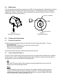
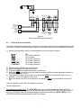
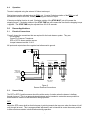
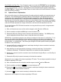
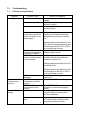
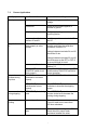
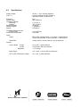
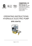
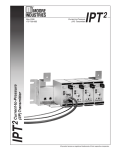
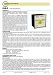
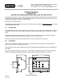
222 W. Memorial Road, Oklahoma City, OK 73126-0508
Phone: 1-800-624-7697 Fax: 405-755-8425
www.magpowr.com E-mail: [email protected]
INSTRUCTION MANUAL
MODEL DFC-A
DANCER-FOLLOWER ARM CONTROL WITH LOW VOLTAGE OUTPUT
All of the information herein is the exclusive proprietary property of Maxcess International, and is disclosed with the
understanding that it will be retained in confidence and will neither be duplicated nor copied in whole or in part nor
be used for any purpose other than for which disclosed.
Copyright 2004, all rights reserved.
Periodically there will be updates to this manual. The latest version is available at www.magpowr.com or by calling
1-800-MAGPOWR (624-7697).
1.0
Introduction
The MAGPOWR Model DFC-A is a complete solution for Follower Arm or Dancer control applications. The DFC-A
provides a 0 to 10 vdc or 4 to 20 ma output to control a current-to-pressure transducer, or a motor drive in torque
mode.
Terminals are provided for the connection of an external 1 madc current meter. The meter display will indicate
output as a percentage of the selected output range (0 to 10 vdc, or 4 to 20 madc).
The inputs and outputs are referenced to earth ground. The DFC-A operates on 24 vdc input.
2.0
Installation
The DFC-A is intended for installation on a vertical panel using a DIN 35 rail, using the wiring terminals facing
down. Figure 1 shows the enclosure dimensions.
All wiring should comply with the essential requirements of the appropriate standard(s) and is the responsibility of
the installer.
Route control signal wiring away from AC wiring. Connect shields of shielded cable to the terminals indicated as
“SHIELD”. Maximum shield length and maximum length of wires outside of the shield is 3 in. (75 mm).
2.30 [58.4mm]
1.39
[35.2mm]
4.13 [105mm]
3.38
[85.8mm]
Figure 1
Enclosure Dimensions
850A273-1
05/06 Rev. D
3.0
Maintenance
The only maintenance that may be required on the DFC-A is fuse replacement. Replacement of the fuse
requires first removing dc power, then opening the enclosure. The enclosure must be re-installed to
maintain the IP rating. The enclosure may be opened by inserting a flat blade screwdriver under the
retaining tabs in the base (See figure 2).
FULL ROLL DIAMETER
DFP
CORE DIAMETER
Figure 2
Enclosure Top Removal
4.0
Follower Arm Applications
4.1
Electrical Connections
Figure 3
Follower Arm Setup
Figure 4 shows the connections that are required for the basic follower arm system. They are:
24 vdc power input
Current-to-Pressure Transducer or a motor drive in torque mode
DFP or DFP-2 roll diameter sensor
10 kohm tension potentiometer
All inputs and outputs have the negative lead referenced to ground.
4.2
Sensor Setup (See Figure 3)
The DFP or DFP-2 position sensor should be at the center of rotation when the follower arm is halfway
through its travel. This is an approximate adjustment and is intended to center the sensor position to
allow maximum rotation in both directions during operation.
DFP
Adjust the DFP sensor shaft so that its keyway is pointing towards the top cover when the
follower arm is half way through its travel.
DFP-2
To find the electrical center point of pot rotation, use a digital multimeter type ohm meter to
measure from the white wire (wiper), to the red or black wire. Turn the potentiometer shaft
until the meter reads 500 ohm. Install the DFP-2 sensor so the meter reading is 500 ohms
when the follower arm is halfway through its travel.
2
24 vdc
19 20
+
24
VDC
21
OUTPUT
1mA
METER
0-10 4-20
+
+ SHIELD +
1
4
2
3
5
6
(OPEN FOR RUN) TENSION
RUN-STOP
9
10
SHIELD +
11 12
13
POSITION
- SHIELD +
14 15 16
17
18
CURRENT-TOPRESSURE
TRANSDUCER
or
TORQUE MOTOR
CW
REMOTE
METER
0-1 madc
(OPTIONAL)
10K
TENSION
RUN/STOP
OPEN FOR RUN
INCREASING
(OPTIONAL)
TENSION
DFP
INCREASING
DIAMETER
Figure 4
Follower Arm Electrical Connections
4.3
Follower Arm Control Setup
The control adjustments marked with an underline on the label are the only ones needed for follower arm
adjustment. Stop time and Stop multiplier apply to all operating modes and are not distinctively marked.
1) Set the following switch and 22-turn potentiometers to the settings given below:
F switch
ZERO
FULL
D
CORE
STOP TIME
STOP MULT
PD
full Counter Clockwise
full Clockwise
full Counter Clockwise
full Counter Clockwise
full Counter Clockwise
full Counter Clockwise
2)
3)
4)
5)
Set the external TENSION pot full Clockwise.
Position the follower arm on an empty core.
Adjust the CORE pot to obtain zero on the remote meter.
Adjust the ZERO pot until the meter just starts to increase, and then reverse adjustment direction to
just return the meter to zero.
6) From published torque versus output curves adjust the CORE pot for the desired output at core.
(Example: y madc to provide xx psi at core.)
7) Place the follower arm at the full roll position, and adjust the FULL pot to the desired output at full
roll.
Setup is complete, and the DFC-A is ready for operation.
Optional adjustments:
Stop Multiplier and Stop Time. The STOP MULT pot can be used to increase the torque while the
machine is stopping. The increased torque is applied when the RUN/STOP input is closed (terminals 9
and 10). The length of time the increased torque is applied is adjusted by the STOP TIME pot. The
STOPPED indicator illuminates when the Stop Time expires.
3
4.4
Operation
Tension is adjusted using the external 10 kohm tension pot.
Rewind taper can be adjusted using the FULL pot. Counter Clockwise rotation of the FULL pot will
decrease the tension at full roll, thereby increasing the amount of taper.
If the stop multiplier function is used, Clockwise rotation of the STOP MULT pot will increase the
stopping torque. Clockwise rotation of the STOP TIME pot will increase the time that the stopping torque
is applied. The STOP TIME may be adjusted from 0.2 to 60 seconds.
5.0
Dancer Applications
5.1
Electrical Connections
Figure 5 shows the connections that are required for the basic dancer system. They are:
24 vdc power
Current-To-Pressure Transducer
DFP or DFP-2 dancer position sensor
Jumper between terminal 12 & 13
All inputs and outputs have the negative lead referenced to ground.
24 vdc
19 20
+
24
VDC
21
OUTPUT
1mA
METER
0-10 4-20
+
+ SHIELD +
3
1
2
5
6
4
(OPEN FOR RUN) TENSION
RUN-STOP
9
10
SHIELD +
11 12
13
POSITION
- SHIELD +
14 15 16
17
18
CURRENT-TOPRESSURE
TRANSDUCER
REMOTE
METER
0-1 madc
(OPTIONAL)
DFP
RUN/STOP
OPEN FOR RUN
(OPTIONAL)
INCREASING
TORQUE
OUTPUT
Figure 5
Dancer Electrical Connections
5.2
Sensor Setup
The DFP or DFP-2 position sensor should be at the center of rotation when the dancer is halfway
through its travel. This is an approximate adjustment and is intended to center the sensor position to
allow maximum rotation in both directions during operation.
DFP
Adjust the DFP sensor shaft so that its keyway is pointing towards the top cover when the dancer is half
way through its travel. This is an approximate adjustment, and is intended to center the sensor position
to allow maximum rotation in both directions during operation.
4
DFP-2
To find the electrical center point of pot rotation, use a digital multimeter type ohm meter to measure from
the white wire (wiper), to the red or black wire. Turn the potentiometer shaft until the meter reads 500
ohm. Install the DFP-2 sensor so the meter reading is 500 ohms when the follower arm is halfway
through its travel.
5.3
Dancer Control Setup and Tuning
The control adjustments marked on the label without an underline or box are the only ones needed for
dancer adjustment. Stop Time and Stop Multiplier apply to all operating modes and are not distinctively
marked.
1) Set the following switch and 22-turn potentiometers to the settings given below:
F switch
P
D
CORE
STOP TIME
STOP MULT
PD
full Clockwise
mid rotation (approximately 11 turns)
full Counter Clockwise
full Counter Clockwise
full Counter Clockwise
2) With the machine running with web, adjust the POS1 pot to center the dancer arm.
3) Adjust the D pot to minimize dancer arm oscillations. The direction to adjust D to minimize
oscillations is system dependent.
4) If dancer arm oscillations cannot be eliminated, turn the P pot Counter Clockwise and repeat step 3.
Calibration is complete, and the DFC-A is ready for operation.
Optional Adjustments:
Integrator. Many machines run quite successfully after the above adjustments have been made. If the
dancer arm moves too much while the roll changes size, the integrator can be turned on to keep the
dancer centered.
The control adjustments marked with a box apply to a dancer with integrator.
5) Set the I pot full Clockwise.
6) With the machine stopped, set the F switch to PID . This turns the integrator on.
7) Run the machine near full roll and at a slow speed and use the POS2 pot to center the dancer.
Clockwise rotation of POS2 moves the dancer up, towards an empty dancer condition.
8) Turn the I pot Counter Clockwise until the dancer begins to oscillate around the setpoint position.
Then, turn the I pot Clockwise until the oscillation stops.
The RUN/STOP input must be used if the integrator is on (F switch in PID position). The RUN/STOP
input should be closed (terminals 9 and 10) when the machine starts its deceleration. The DFC-A keeps
the integrator on until Stop Time expires. Stop Time may be increased by Clockwise rotation of the
STOP TIME pot. The STOPPED indicator illuminates when the Stop Time has expired. While the
STOPPED indicator is illuminated the DFC-A provides a hold level output that may be adjusted by
turning the HOLD pot.
5
Stop Multiplier and Stop Time. Even if integrator mode is not used, the STOP MULT pot can be used to
increase the torque while the machine is stopping. The increased torque is applied when the RUN/STOP
input is closed (terminals 17 and 18). The length of time the increased torque is applied is adjusted by
the STOP TIME pot. Using the stop multiplier feature in dancer mode could cause the dancer to oscillate
while the machine is stopping.
6.0
Optional Dancer Optimization
After tuning of the dancer, the following method will usually optimize the stability and responsiveness of
the dancer. The method begins by placing the dancer in PD mode with a roll diameter near core and
reducing the gain to a level which the user may consider unacceptable. Gain will subsequently be
increased to a more desirable level. If using PID mode, the dancer is placed in PID mode with a roll
diameter near full roll and the integrator is reduced to a level which the user may consider unacceptable.
Then, the integrator will be increased to a more desirable level. Sometimes, it may be necessary to first
make the PD mode adjustment at a larger roll diameter, and then refine the adjustment near core.
Do not switch between PD/ PID while the machine is running since this may result in a large transient
jump in the output.
1) With a roll diameter near core and the machine stopped, set the F switch to PD mode.
2) Run the machine and adjust the POS1 pot to center the dancer arm.
3) Decrease the P pot by rotating Counter Clockwise until the dancer stabilizes. The POS1 pot may
require readjustment several times in order to keep the dancer roll centered.
DEFINITION: In the following steps the user will have to determine if the dancer is overshooting. To do
this, move the stable dancer away from its set position by pushing on the dancer, by bumping the
unwind/rewind roll, or by some similar means. If the dancer goes past the set position before settling to
the set position, it is overshooting. If the dancer goes straight to the stable position without going past it,
the dancer is not overshooting.
4) Increase the P pot by rotating Clockwise in small steps checking for dancer overshoot at each step.
Do this until overshoot is obtained.
5) Adjust the D pot in small steps checking for dancer overshoot at each step. Do this until the
overshoot is eliminated. The direction to adjust D for no overshoot is system dependent.
6) Repeat steps (4) and (5) until the overshoot cannot be eliminated using the D pot, or until the P pot is
full Clockwise.
7) Decrease the P pot by the amount necessary to eliminate the overshoot.
Adjustment is now complete for the dancer operating in PD mode. The next steps complete the tuning of
the dancer operating in PID mode.
8) With a roll diameter near full roll and the machine stopped, set the F switch to PID mode.
9) Run the machine and adjust the POS2 pot to center the dancer roll.
10) Decrease the I pot by rotating Counter Clockwise in small steps checking for dancer overshoot at
each step. Do this until overshoot is obtained.
11) Increase the I pot by the amount necessary to eliminate the overshoot.
Adjustment is now complete for the dancer operating in PID mode.
6
7.0
Troubleshooting
7.1
Follower Arm Applications
Symptom
No output.
Possible Cause
No DC power.
Fuse blown.
Output wires open circuit.
Remote tension adjust
potentiometer turned full
counter clockwise or not
wired properly.
Remote tension
potentiometer resistance
is less than 10 kohms.
DFP, DFP-2 position
sensor not wired properly
or wires shorted.
Solution or Diagnostic
Verify incoming power is the correct
voltage.
Output wires shorted together or
shorted to ground.
Verify output voltage or current at the
receiving device.
Verify tension pot wiring, turn tension
adjust pot full clockwise and follow
the calibration procedure in section
4.3.
Voltage between terminals 20(+) and
22(-) should be greater than zero and
should change as the DFP or DFP-2
is moved through its travel.
Use a 10 kohm potentiometer for the
Remote tension control.
Verify position sensor is wired
properly and follow the calibration
procedure in section 4.3.
Voltage between terminals 24 and 26
should be 10 vdc.
Output does not
increase during
stop time.
Remote meter not
working.
Follower Arm not
calibrated.
RUN/STOP switch not
connected or not wired
properly.
STOP MULTiplier
potentiometer not set
properly.
Incorrect type of meter.
Meter wires shorted or
open.
Voltage between terminals 25 and 26
should change as the DFP or DFP-2
is moved through its travel.
Follow the calibration procedure in
section 4.3.
Verify RUN/STOP switch wiring.
Turn STOP MULT potentiometer
clockwise to increase the stopping
torque.
Meter should be a current meter with
1 ma full scale and no more than
500 ohm resistance.
Disconnect meter wiring at the
DFC-A and check for proper meter
resistance between the wires.
7
7.2
Dancer Applications
Symptom
No output.
Output full on or full
off.
Possible Cause
No DC power.
Solution or Diagnostic
Verify incoming power is the correct
voltage.
Fuse blown.
Output wires shorted together or
shorted to ground.
Output wires open circuit.
Verify output voltage or current at the
receiving device.
Jumper not installed
between 20 and 21.
DFP or DFP-2 sensor not
wired properly or wires
shorted.
Install jumper between terminals 20
and 21.
Verify DFP or DFP-2 sensor is wired
properly and follow the calibration
procedure in section 5.3.
Voltage between terminals 24 and 26
should be 10 vdc.
Dancer not calibrated.
Output does not
increase during
stop time.
DFC-A in PID mode and
RUN/STOP switch is not
wired properly.
RUN/STOP switch not
connected or not wired
properly.
Voltage between terminals 25 and 26
should change as the DFP or DFP-2
is moved through its travel.
Follow the calibration procedure in
section 5.3.
Verify RUN/STOP switch wiring. PID
mode needs a RUN/STOP switch for
proper operation.
Verify RUN/STOP switch wiring.
STOP MULTiplier
potentiometer not set
properly.
Turn STOP MULT potentiometer
clockwise to increase the stopping
torque.
Dancer arm hunting
during stopping.
STOP MULTiplier is being
used.
Turn STOP MULT potentiometer
counter clockwise to decrease the
hunting during stopping.
Remote meter not
working.
Incorrect type of meter.
Meter should be a current meter with
1 ma full scale and no more than
500 ohm resistance.
Meter wires shorted or
open.
Disconnect meter wiring at the DFCA and check for proper meter
resistance between the wires.
8
8.0
Specifications
Supply Voltage:
Fuse: F1
24 vdc, +/- 10%, 0.08 amp maximum
2.0 amp, Littelfuse Part No. 216.002, or
Wickmann Part No. 19194-057-FS
Enclosure:
Climatic Class:
Temperature Range:
Operating:
Storage:
Relative Humidity:
Pollution Degree:
Altitude:
IP20
3K3 (EN60721)
0° C to 50° C
-30° C to 80° C
5% to 85%
2 (IEC664-1)
0 to 2000 m
Compatible Residual Current
Device Types:
Worst Case Fault Current:
A or B (IEC755)
2.0 amp dc
Inputs:
Signal:
DFP or DFP-2 Potentiometer: 1 to 10 kohm, ¼ watt minimum
Tension Potentiometer: 10 kohm minimum, ¼ watt minimum
RUN/STOP:
Contact closure, 30 ohm maximum, 0.2 vdc maximum
Outputs:
Clutch / Brake:
Voltage:
Current:
Regulation:
0 to 10 vdc, 1 madc maximum
4 to 20 madc, 400 ohm maximum
< 1% of range
Meter Signal:
0 to 1 madc, +/-2% into 500 ohm maximum
DFP or DFP-2 Reference Voltage:
10v +/-2%, 10 madc maximum