1
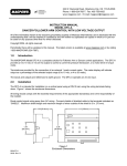
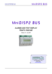
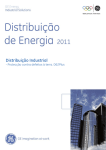
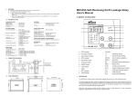
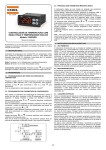
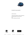
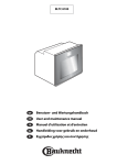
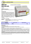
INSTRUCTION MANUAL
IM208-U v1.01
ELR-2
EARTH LEAKAGE RELAY
GENERALITY
The device type ELR-2 is an amperometric relay of maximum
homopolar differential current to use to control the insulation
towards earth of networks of energy supplier, of electric
machines, etc.
The device must be joined at a suitable toroidal current
transformer of the CT line in the way to point out the earth
leakage current of the system to control and to protect. The
toroidal current transformer point out the vectorial sum of the
currents present on the active conductor of single-phase line,
three-phase with or without neutral (inside the toroidal current
transformer will pass all phase conductor and if present the
neutral, but none protection conductor must pass), in the way
to point up the leakage current towards earth, depend of the
insulation level line under control.
When the current read exceed the threshold value set the two
exchanging contacts, available in output, will commute in the
way to protect the line under control using opportune opening
coils switch or contactor or to signal at distance the low
insulation condition of the line or equipment under control.
INTRODUCTION
The ELR-2 has standard dimensions DIN 96x96mm with depth very limited, in the way to use it in application where the
space available is limited.
A wide range of current and time of delay calibration, allows to use it in a lot of application, both like signalling of low
insulation and like protection line according with the norms (CEI 64.8), to realize adequate vertical and horizontal
selectivity, etc.
The device has, on input circuits of the measure circuit opportune filters doing it exempt by external noises, permanent
control function of efficiency of internal circuit, permanent control of connection between relay and toroidal current
transformer and coil continuity with test at 4 wires, in the way to verify the efficiency of system relay + toroidal current
transformer. The functioning is insured also with sinusoidal current and unidirectional button (type A according to norms
IEC 755).
On the front it’s possible to program the tripping current (25mA ÷ 25 A), the tripping delay (0,02 ÷ 5 sec.), the activation of
the alarm threshold and the type of functioning of output relays. The device has two contacts in exchange in output for
tripping and prealarm (both for the application with a closed contact and opened contact), the possibility of functioning
with the manual or automatic reset, the connection for eventually bottom of reset at distance, an apposite transparent
cover of frontal protection and lateral screw terminals.
MODELS:
In basis of power supply there are three models:
- ELR-2-230: 100÷125Vca - 220÷240Vca - 380÷415Vca
- ELR-2-24:
24V ca/cc - 48V ca/cc
- ELR-2-110: 100-125V ca/cc
On request are available others power supplies.
ACCESSORIES AND OPTION
accessories: transparent cover of frontal protection
INSTALLATION
Only a qualified technician can do the installation. The instrument installation must be done in total absence of voltage.
The instrument must be intact and it haven’t damages caused of transport. The power supply must be compatible with the
tool range. To fix the device at the panel, insert the two bracket into apposite button-holes in the side of the enclosure and
to shut the screw. The transparent cover is fixed at the upper part at joint. To remove the cover it’s necessary to act on
the two hooks in a side of the frontal part of the instrument with a screwdriver.
The wire of connection between the relay and the toroidal current transformer must be twisted or shielded in presence of
strong electromagnetic noises or considerable length. It’s better to use a cable with a section of 1 mm2 and a length lower
than 30 meters. The toroidal current transformer must be connected at the terminals 1-2 (coil of measure) and the
terminals 3-4 (coil of test) for the function of test.
The relay trip if the connection is interrupted (function of permanent control of the efficiency of the connection circuit). To
test the device it’s possible to use the bottom of TEST that caused the intervention of relay after the delay set.
ELR-2
instruction manual
IM208-U v1.01
pag. 1 / 4
DESCRIPTION – PROGRAMMING
1
5
6
9
7
REAR PANEL
11 12 13 14 15 16
ELR-2
2
Earth Leakage Relay
relè differenziale di terra
input test signal
current
output
remote
current transformer RESET
TR...
(auto reset)
ouput relay
ALARM
(TRIP 2)
V aux.
1,5
1
0,5
2
0,25
2,5
ON
TRIP
Ι∆n(A)
0,2
0,1
0,05
0,02
0,3
0,5
t (sec)
alarm off
tx10
I∆x1
Ι∆x10
FS trip
FS alarm
TEST
2
1
0,4
005A MADE IN ITALY
3
ouput relay
TRIP
4 5 6 7 8 9
4
alarm on
tx1
Ι∆x0,1
off
off
8
RESET
1
FAIL SAFE
10
alarm off
tx10
Ι∆x1
Ι∆x10
FS trip
FS alarm
0
a
b
c
d
e
f
alarm on
tx1
Ι∆x0,1
off
off
FAIL SAFE
3
Legenda:
1)
2)
3)
4)
5)
6)
7)
8)
9)
ELR-2
current tripping setting potentiometer
tripping time setting potentiometer
push button for test
push button for manual reset
signalling green LED for auxiliary supply
presence
signalling yellow LED of alarm tripped
signalling red LED of relay tripped
screw terminals for the connection of the
power supply and contacts of output relays
screw terminals for the connection at the
toroidal current transformer and for the
reset at distance or automatic
instruction manual
10) microiswitches of programming:
- a. selection of the activation alarm function
in position 1 the alarm function is disabled
in position 0 the alarm function is enabled
- b. selection of the multiplying constant of tripping time
in position 1 K=10
in position 0 K=1
- c,d selection of the multiplying constant of tripping current
with c,d in position 0 K=0,1
with c in position 1, d in position 0 K=1
with c,d in position 1 K=10
- e selection of the type of functioning of the TRIP relay
in position 1 the relay is energized at rest
(FAIL SAFE)
in position 0 the relay is de-energized at rest
- f selection of the type of functioning of the ALARM relay
in position 1 the relay is energized at rest
(FAIL SAFE)
in position 0 the relay is de-energized at rest
IM208-U v1.01
pag. 2 / 4
WIRING DIAGRAMS
Example of wiring diagram with switch
with opening coil with output relay
energized (fail safe off).
Earth
Aux
x x
x x
*
ouput relay
ALARM
(TRIP 2)
CT...
input
current
remote
test
RESET
signal
output (auto reset)
ouput relay
TRIP
The output contacts can be
used to signal the relay
tripped.
The ALARM relay allows
to signal the current besides
the 60% of threshold set
(if ALARM ON is selected).
ELR-2
11 12 13 14 15 16
* power supply Vaux:
ELR-2-230
- terminals 1 - 2 = 100-125V ca
- terminals 2 - 3 = 220-240V ca
- terminals 1 - 3 = 380-415V ca
ELR2-115
- terminals 1 - 2 = 100-125V ca/cc
ELR-2-24
- terminals 1 - 2 = 24 V ca/cc
- terminals 1 - 3 = 48 V ca/cc
connection at toroidal current transformer:
terminals 11-12
to connect at measure coil
terminals 13-14
to connect at test coil
connection reset at distance or automatic
reset:
terminals 15-16
to connect at a external botton with contact
normally open
to realize the function of automatic reset, to
short-circuit the terminals
connection contacts output relay:
terminals 7-8-9 of TRIP relay
the contact 7-8 is normally closed if
FAIL-SAFE OFF is selected or without
power supply
with FAIL-SAFE TRIP ON the contact will
be normally opened in condition of rest
terminals 4-5-6 of ALARM relay (TRIP2)
the contact 4-5 is normally closed if
FAIL-SAFE OFF is selected or without
power supply
with FAIL-SAFE ALARM ON the contact will
be normally opened in condition of rest
FUNCTIONALITY
When the device is installed and correctly supplied, its green LED will be on and the output relays commuted if the
functions FAIL SAFE ON (relays normally energized) are selected. The eventual trip of relays can depend by an
interruption of the toroid–relay circuit or by a presence of earth leakage current higher than the value set.
The function FAIL SAFE allows the commutation of output relay, besides at the normal intervention for the overcoming of
the current threshold, also for damage of relay or for absence of power supply.
When the instrument switch on, the relays will commute (normally energized), after in the condition of trip or if the power
supply is absent the relays come back de-energized.
If the ALARM ON is set, the ALARM (TRIP2) output relay will commute when the current measured reach the 60% of the
threshold set; in this way it’s possible to have a signalling of increase of the earth leakage current, but not yet at the level
to need the opening of the line under control. If the ALARM OFF is set, the two output relays will commute together, in the
way to use a contact for the opening the switch jointed and the other for a signalling at distance of tripping relay.
To realize the automatic reset it’s necessary to short-circuit the terminals 15-16, in the way that if the current measured
descend under the level of the threshold set, the relay will rearm automatically. If after the trip the power supply
disappears, the relay will rearm automatically. If it’s impossible to rearm the relay depends by a current measured upper
than the threshold or the connection between relay and toroidal current transformer is interrupted.
ELR-2
instruction manual
IM208-U v1.01
pag. 3 / 4
TECHNICAL FEATURES
Auxiliary power supply
Maximum consumption
Current tripping adjustment range Ι∆n
Tripping time adjustment range t
Signalling
Alarm tripping
External toroidal current transformer and
accessories
Output relay: voltage free contacts
Functions programmable
Working temperature
Storing temperature
Relative humidity
Insulation test
Position of mounting
Type of connection
Protection degree
Mounting DIN 43700
Standards
Electromagnetic compatibility
ELR-2-230: 100÷125V 220÷240V 380-415V 50-60Hz
ELR-2-115: 100÷125V cc/dc 50-60Hz ±10%
ELR-2-24: 24 – 48V cc/dc 50-60Hz ±20%
4 VA
0,025 ÷ 0,25 A for K = 0,1
0,25 ÷ 2,5 A for K = 1
2,5 ÷ 25 A for K = 10
0,02 ÷ 0,5 sec. for K =1
0,2 ÷ 5 sec. for K =10
led ON, led ALARM, led TRIP
60% of threshold tripping Ι∆n (disabling)
±10%
TR… serie
2 changeover contacts NO-C-NC 5 A 250V resistive load
function alarm output, function fail safe for both outputs,
automatic (external reset) or manual reset
-10 ÷ 60°C
-20 ÷ 70°C
≤ 90 %
2,5 kV 60 sec.
Indifferent
Extractible terminal with screws, section wires max 2,5 mm2
IP 52 front with cover (IP40 without cover) - IP 20 enclosure
Flush mounting DIN 96x96mm, depth 56mm
CEI 41-1
IEC 255 VDE 0664 IEC755 CEI 64.8
EN 61008-1 (1999-11); EN 62020 (1999-09); EN 61543 (199609); EN61326-1 (1998-04);EN 61326/A1 (1999-05)
CEI-EN 50081-1
CEI-EN 50082-2
DIMENSIONS
96
Earth Leakage Relay
relè differenziale di terra
TEST
TRIP
0,2
0,1
0,05
0,02
0,3
0,4
0,5
t (sec)
alarm off
tx1 0
I∆x1
Ι∆ x10
FS t rip
FS alarm
alarm on
tx1
90
ON
96
2
2,5
Ι∆n(A)
96
1,5
1
0,5
0,25
56
R3
92
ELR-2
18
Ι∆x0,1
off
off
92
RESET
FAIL SAFE
20
Contact the technical assistance or refer at specific document for applications don’t described in this manual.
NOTE
At reason of the evolution of standards and products, the company reserves to modify in every time the features of the product described in this
document, that it’s necessary to verify preventively.
The liability of the producer for damage caused by defect of the product ”can be reduced or deleted (…) when the damage is caused joint by a defect of
product or for blame of the damaged or a person of which the damaged is responsible” (Article 8, 85/374/CEE).
ELR-2
instruction manual
IM208-U v1.01
pag. 4 / 4