1
BJ192e-3X4 Multi-Power Meter
User Manual
Version:
:1.2
● Please read carefully before using this user manual
● Please save this document
1. - SPECIFICATIONS
Input
Voltage: Rated 400V (optional 100V)
Current: Rated 20A directly connection
Frequency: 45-65Hz
Load
Voltage: <0.5VA / phase (rated 220V)
Current: <0.5VA / phase (rated 20A)
Overload
Current: 1.2 times rated continuous; 10 seconds for 10 times the rated
Voltage: 1.2 times the rated continuous; 10 seconds for 800V
Dielectric strength
IEC 688 / IEC 255-3 (1989)
2kV AC RMS 1 minute, between input / output / case / power supply
EMC Test
Electrostatic discharge immunity
test:
Electrical fast transient burst
immunity test
Surge (Shock) immunity test
standard
Test voltage
IEC-61000-4-2
level 4
8Kv
IEC61000-4-4
level 3
IEC61000-4-5
level 4
Work environment
Temperature: -20℃~ +60℃
Humidity: RH 20%~95%(No condensation)
Input 1kV; Power supply 2kV
common mode test voltage 4kV
Protection
Panel: IP40
Storage Conditions
Temperature:-25℃~+70℃
Humidity: RH 20%~95%
Working Power
AC 85-265VAC/DC, 45-65Hz
Maximum power consumption 6W
Dimensions
L × W × H =72mm×72mm×123mm
Installation hole size
L × W = (66+0.8mm) × (66+0.8mm)
2. - INSTALLATION AND START-UP
The manual you hold in your hand contains information and warnings that the
user should respect in order to guarantee a proper operation of all the
instrument functions and keep its safety conditions. The instrument must not
be powered on and used until its definitive assembly on the cabinet’s door.
If the instrument is not used as manufacturer’s specifications, the protection of the
instrument will be damaged.
When any protection failure is suspected to exist (for example, it presents external visible
damages), the instrument must be immediately powered off. In this case contact a
qualified service representative.
2.1.- Installation
Mounting
Instrument is to be mounted on panel (cut-out 66+0.8 x 66+0.8 mm). All connections keep
inside the cabinet.
Note that with the instrument powered on, the terminals could be dangerous to touching
and cover opening actions or elements removal may allow accessing dangerous parts.
Therefore, the instrument must not be used until this is completely installed.
Notes:
Input signal: BJ192e using a separate acquisition calculate for each measurement
channel, to ensure consistent in use, for different load forms, its a variety of connection
mode.
A. Voltage input:
Input voltage should not exceed the rated input voltage products (100V or 400V),
Otherwise, should use external CT, the input voltage to be installed in the 1A fuse.
B. Current Input:
Standard input current is 20A, if greater than 20A should use external CT.
Even if you are using on the CT are connecting with other instruments, wiring methods
should be used in series. Before remove the current input connection, must be sure to
disconnect the primary circuit or shorted secondary circuit of CT. Suggest using the
terminal block, please not directly connect to CT, in order to facilitate disassembly.
Auxiliary power:
BJ192e-3X4 Multifunction Power Meter with universal (AC / DC) power input, if not for a
special statement, we provide the 220VAC/DC or 110VAC/DC power interface for
standard products. Instruments limit work power supply: AC / DC: 85-265V, please
ensure that the auxiliary power can match for BJ192E series meter to prevent damage
to the product.
A. Suggest install 1A fuse in the fire line side.
B. For the areas with poor power quality, suggest install lightning surge suppressor and
rapid burst suppressor to prevent lightning strikes.
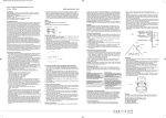
2.2. - Connection terminal (see label on the rear part)
1. *Supply voltage input: 0 V
2. *Supply voltage input:220 Va.c.
4. Current A-phase - S1 input
5. Current A-phase - S2 input
6. Current B-phase - S1 input
7. Current B-phase - S2 input
8. Current C-phase - S1 input
9. Current C-phase - S2 input
11. Voltage A-phase input
12. Voltage B-phase input
13. Voltage C-phase input
14. Neutral Voltage input
58. RS-485 ( + )
59. RS-485 ( - )
60. RS-485 ( GND )
Three-phase network.- 3 wires (low voltage) :
IMPORTANT REMARK!
If power = -0.01 is shown for any of the phases and voltage and current are not zero for
this phase, check out following points:
- Assure that A,B,C phases coincide in voltage and current.
- Correct polarity? Reverse the current transformer placed at this phase.
2.3.- Mounting
BJ-192e-3X4 is for panel mounting, controller is to be
mounted on panel (cut-out 66+0.5 x 66+0.5 mm). All
connections keep inside the cabinet.
Notes:
1. The controller must not be power on until this is completely installed.
2. Panels shall not exceed 12 mm maximum thickness, If more than this range,
please consider using the rail mounting
3. - OPERATION MODE
The instrument has three line displays. Each one has also two LED type indicators (red
colour). Every led will be on according to the parameter presently shown in screen.
When the 192e-3X4 is powered up, all the LED indicator will on, and meter start self- test,
after some seconds, the meter is ready for operation and shows one of the available
screens.
Press this key, the meter will show the measured data in different screen, the change turn
is U, V, I, I0, h
When show the data, the LED indicator will on and show the related parameter.
Press this key, the meter will change the measurement data in the instantaneous value,
average value and maximum value as the current shown data.
Press this key, can reset the maximum value and average value to zero.
The SETUP procedure of the BJ192e-X is performed by means of several SETUP
options.
Once into the SETUP, use the keyboard to select different options and enter required
variables:
1. Password enter
2. Input signal selection
3. Communication preferences
4.- SAFETY CONSIDERATIONS
All installation specification described at the previous chapters named :
INSTALLATION AND STARTUP, OPERATION MODE and
SPECIFICATIONS.
Note that with the instrument powered on, the terminals could be
dangerous to touching and cover opening actions or elements removal
may allow accessing dangerous parts. This instrument is actory-shipped
at proper operation condition.
5.- MAINTENANCE
The 192e-3X4 does not require any special maintenance. No adjustment, maintenance or
repairing action should be done when the instrument open and powered on, should those
actions are essential, high-qualified operators must perform them.
Before any adjustment, replacement, maintenance or repairing operation is carried out,
the instrument must be disconnected from any power supply source.
When any protection failure is suspected to exist, the instrument must be immediately put
our of service. The instrument’s design allows a quick replacement in case of any failure.
6.- TECHNICAL SERVICE
For any inquiry about the instrument performance or whether any failure happens, contact
to Blue Jay’s technical service.
Blue Jay - After-sales service
Redstone Road 2# 17-3
Jiangbei District , 400020 Chongqing
Tel - + 0086 023 67636974
Fax - + 0086 023 67636974
E-mail : [email protected]