1
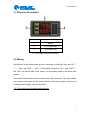
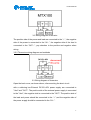
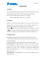
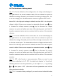
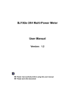
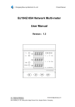
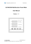
Product Manual
MTX100
Better Meter
User MANUAL
Version 1.4
Tel: +0086-023-86850812
Email:[email protected]
Fax:+0086-023-67636974
Add: Building 13, 2-8, Jialing third village Pioneer Park, Jiangbei District, Chongqing
Product Manual
Contents
1. Inspecting Package Contents ................................................. 1
1.1 Check if there is damage due to transportation .................... 1
1.2 Check package contents ...................................................... 1
1.3 Check the machine .............................................................. 1
2. Summary .................................................................................. 1
2.1 Brief introduction .................................................................. 1
2.2 Main function ....................................................................... 2
2.3 Technical data ...................................................................... 2
3.Instrument Introduction ........................................................... 2
3.1 Structure Description............................................................ 3
3.2 Wiring .................................................................................. 3
4. Operation ................................................................................. 5
4.1 Wiring .................................................................................. 5
4.2 Output .................................................................................. 5
4.3 Debug mode ........................................................................ 5
4.4 The functions of debug mode............................................... 6
5. Cautions ................................................................................... 7
6. Warranty and service .............................................................. 7
Tel: +0086-023-86850812
Email:[email protected]
Fax:+0086-023-67636974
Add: Building 13, 2-8, Jialing third village Pioneer Park, Jiangbei District, Chongqing
Product Manual
1. Inspecting Package Contents
When you get a new MTX100 Voltage Meter, please inspect the instrument as
follows:
1.1 Check if there is damage due to transportation
If the package is damaged, please retain them until the instrument and
accessories are tested.
1.2 Check package contents
Contents of the case are as bellows, if the content does not match with the
packing list or the instrument is damaged, please contact us.
MTX100 Voltage Meter
1pc
User manual(pdf)
1pc
1.3 Check the machine
If the machine was damaged; did not work properly or failed to pass
performance tests, please contact your dealer or our company.
2. Summary
2.1 Brief introduction
MTX100 is a new-type voltage meter which can measure voltage, current,
power, charging capacity and time at the same time.The voltage meter adopts
two groups of LED digital tubes to display the data. The meter can switch the
display among different physical quantities.This meter is ideal for monitoring
the output voltage and current, as well as the battery charge and discharge
applications.
1
Product Manual
2.2 Main function
1、Dual display for voltage and current, and available for switching display
power, charge capacity and time.
2、Flexible calibration function, you can calibrate the voltage and current value
by yourself.
3、4-bit LED digital tube, in which 3-bit for measuring and one-bit for the unit.
4、Convenient and easy to carry, easy to operate.
2.3 Technical data
Item
Parameter
Two wire system
10V~90V
Three wire system
0~90V
Input voltage
Output current
0~20A
Display
4 bit LED(3 bit for value and 1 bit for unit)
Display
resolution
Voltage
0.01V
Current
0.01A
Power
0.01W
Capacity
0.01AH
Time
0.01H
Voltage
±1%+2 bytes
Current
±2%+5 bytes
Accuracy
Measuring rate
5times/s
Dimensions(W*H*D)
79×43×25(mm)
Installing hole (mm)
76.5*39.2(mm)
2-1 Technical data
3.Instrument Introduction
2
Product Manual
3.1 Structure Description
Item
Introduction
1
Button
2
LED digital tube
3
Operation Tips
4-1 The introduction of MTX100P
3.2 Wiring
On the back of the meter there are four terminals on the right, they are “IN-”,
“+” , “Vext” and “OUT-”, the”+”is the public terminal of “IN +” and “OUT +” ,
the “Vext” on the left side of the meter, it is the positive side of the three-wire
system.
This meter has two-wire and three-wire dual input methods. Two wire system
can connect the meter to the circuit directly, three-wire system requires an
external power supply for the instrument.
3.2.1 Two-wire wiring diagram and methods
3
Product Manual
3-2 Wiring diagram of two-wire
The positive side of the power and load are connected to the “+”, the negative
side of the power is connected to the “IN-”, the negative side of the load is
connected to the “OUT-”, pay attention to the positive and negative when
wiring.
3.2.2 Three-wire wiring diagram and methods
3-3 Wiring diagram of three-wire
Open the back cover, as shown above, disconnecting the short circuit
with a soldering iron.External DC12V~60V power supply are connected to
"Vext" and "OUT-". The positive side of the external power supply is connected
to the "Vext", the negative side is connected to the "OUT-".The positive side of
the load and power should be connected to the “+”,and the negative side of
the power supply should be connected to the “IN-”.
4
Product Manual
4. Operation
4.1 Wiring
Select the appropriate wiring according to the range of the measured voltage,
ensuring input voltage is within the tolerance range of the instrument.
Note: The input voltage range of two-wire : 10V ~ 70/90V;
The input voltage range of three-wire : 0V ~ 70/90V.
4.2 Output
Please be sure that the input voltage is in the range of the meter can
withstand.Power on, the above digital tube will display voltage value in
default,the below digital tube will display current value in default.
Press the
the
button to select the above display of the digital tube, press
button to select the below display of the digital tube. Flexibility to switch
the display of voltage (V), current (A), power (P), capacity (C) and time (H).
4.3 Debug mode
The following settings are also need to enter debug mode, respectively:
1, When there is a certain error of the measured voltage or current value and
need to be calibrated.
2, When the parameters are confused, need to restore factory settings.
Enter debug mode : In the normal state, press the < OUT >key for a while,
you have entered the debug mode when the the upper row of digital tube
displays "0-U ", press < OUT > key again , the upper row of digital tubes
display alternately among “0 - U”, “1 -C”, “2 - ES” and “3 - r”,each one
represents a function.
Exit debug mode : In the debug mode, you can exit by pressing the < OUT >
button for a while.
5
Product Manual
4.4 The functions of debug mode
4.4.1 "0 - U" is the calibration of the voltage value, the voltage value displays in
the digital tube is the current measure value. We can choose two points to
calibrate the voltage. Generally, we choose 32V as the high voltage point, 12V
as the low voltage point. The demarcation criterion of highs and lows is 20V.
Above 20V is the high point voltage in default, less than 20V is the low point
voltage in default. Now we can compare to a standard voltmeter, press
to increase the voltage measure, press
key
key to decrease the voltage
measure, two points will affect each other. After adjusting back and forth 2-3
times,the measured values can be consistent with the values of the standard
voltmeter.
4.4.2 "1 - C" is the calibration of the current value, the current value displays in
the digital tube is the current measure value. We can choose two points to
calibrate the voltage. Generally, we choose 3A as the high current point, 0.1A
as the low current point. The demarcation criterion of highs and lows is 2A,
Above 2A is the high point current in default, less than 2A is the low point
current in default. Now we can compare to a standard ammeter, press
to increase the current measure, press
key
key to decrease the current
measure, two points will affect each other. After adjusting back and forth 2-3
times,the measured values can be consistent with the values of the standard
ammeter.
4.4.3 "2 - ES" is the function to save parameters. When you need to save
parameters, adjusting to the "2 - ES", the digital tube displays "-n-" by default,
indicating that don’t save the parameters, you can adjust to "- y -" by pressing
or
, then press < OUT >,the meter will save parameters and exit the
debug mode automatically.
5.4.4 "3 - r" is to restore factory settings, if you want to return to the initial value,
6
Product Manual
you can adjust to "- y -" by pressing
or
, then press< OUT >, it will
restore to the factory setting.
5. Cautions
5.1 Don’t exceed the range of the meter, otherwise it will damage the module.
5.2 Connect input and output properly , it is forbid to reverse connection,
otherwise it will not measure correctly.
5.3 Operating temperature is from -10 to 50 degrees Celsius, and storage
temperature is from -20 to 70 degrees Celsius; make sure the instrument kept
dry.
5.4 Do not attempt to disassemble the instrument, destroying the package will
void the warranty, this instrument has no user-serviceable parts inside, if it
need to be repaired, you can repair it by specifying outlets, or return to the
factory for repair.
5.5 Do not move the instrument violently as it is working to avoid irreparable
damage to the internal circuitry.
6. Warranty and service
Thank you for purchasing our products. To maximize the use of the new
product features, we recommend that you take the following steps:
1 Read safe and efficient use instruction.
2 Read the warranty terms and conditions.
We warrants to the original purchaser that its product and the component parts
thereof will be free from defects in workmanship and materials for a period of
one year from the data of purchase.
We will repair or replace, at its’ option, defective product or component parts.
Returned product must be accompanied by proof of the purchase date.
Exclusions: This warranty does not apply in the event of misuse or abuse of
product or as a result of unauthorized alternations or reapers. It is void if the
serial number is alternated, defaced or removed.
7