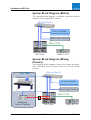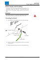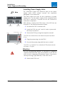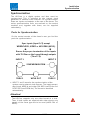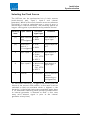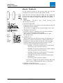
1
HD Core
System Manual
Release:
Issue:
V1.01
04-02-12
interstage
Phistersvej 31, 2900 Hellerup, Danmark
Telefon 3946 0000, fax 3946 0040
www.interstage.dk
- pro audio with a smile
Copyright
All rights reserved. Permission to reprint or electronically reproduce any document or
graphic in whole or in part for any reason is expressly prohibited, unless prior written
consent is obtained from the Lawo AG.
All trademarks and registered trademarks belong to their respective owners. It cannot be
guaranteed that all product names, products, trademarks, requisitions, regulations,
guidelines, specifications and norms are free from trade mark rights of third parties.
All entries in this document have been thoroughly checked; however no guarantee for
correctness can be given. Lawo AG cannot be held responsible for any misleading or
incorrect information provided throughout this manual.
Lawo AG reserves the right to change specifications at any time without notice.
© Lawo AG, 2004
interstage
Phistersvej 31, 2900 Hellerup, Danmark
Telefon 3946 0000, fax 3946 0040
www.interstage.dk
- pro audio with a smile
Contents
Contents
PREFACE
About this manual
Manual Structure
Typographical Markers
Conventions of the Notes
WARNING NOTES
INTRODUCTION HD CORE
Front
Rear
System Block Diagram (Matrix)
System Block Diagram (Mixing Console)
INSTALLATION
Warning Notes
Fitting the Frame
Ambient Conditions
Air-conditioning Requirements
Replacing of Fans
Power Supply and Grounding
Grounding the System
Installing Power Supply Units
Assembly of the HD Core
Warning notices for assembly
Connector Panels
Mounting of Connector Panels
Slots at the Front
Plug-in Cards
Equipping with Plug-in Cards
Procedure of Equipping
Synchronisation
Ports for Synchronisation
Selecting the Clock Source
Alarm/ Contacts
TECHNICAL DETAILS
980/01 Frame
980/22 PSU
980/14 Connector Panel D-Sub
980/15 Connector Panel BNC
980/31 Module ROUTER
981/32 Module ROUTER
HD Core
V1.01
5
5
5
5
6
7
9
9
9
10
10
11
11
11
11
12
12
13
13
14
15
15
16
17
18
19
20
21
23
23
25
26
29
30
31
32
33
34
36
3
Contents
981/02
981/31
981/32
981/56
983/02
GLOSSARY
INDEX
4
Module AES3
Module MADI
Modul MADI
Module ATM
Module DSP
38
39
40
41
42
43
45
V1.01
HD Core
Preface
Preface
About this manual
The HD Core is the central component of the products
Nova73 HD (application matrix) and mc² series HD
(application mixing console).
This manual gives instructions for preparing and installing
the system core. It serves as a reference book for the
system administrator and the service staff.
Manual Structure
The following paragraphs explain briefly the contents of
the chapters. This gives you a detailled overview over the
manual structure.
Chapter 1 Warning Notices
Includes general warnings about the handling of low
voltage devices and first aid in case of electric shock.
Chapter 2 Introduction about HD Core
Offers a brief overview over the system components as well
as a block diagram that illustrates a possible system
structure.
Chapter 3 Commissioning
Describes the installation of the plug-in cards, the power
supply units and the fans. Please note the safety
instructions.
Chapter 4 Technical Details
In this chapter you find a detailled description of the
individual components.
Typographical Markers
For easy handling and orientation with this manual at hand
you will find here some explanations about the most
important typographical markers.
Chapter
The headlines are marked by bold and large font. The
headlines structure the topics to guarantee fast
orientation.
1. Instruction
HD Core
V1.01
5
Preface
The instructions are listed with numbers. These numbers
serve for showing you the reasonable sequence of actions.
This way you have always an overview over the complete
instruction sequence.
Result
The results are written in italic letters. They inform about
intermediate as well as final results to give you the chance
to identify errors at an early stage.
Marginal Note
Marginal Note
The marginal note serves as eye-catcher. Next to the
marginal note you will find useful tips, notes or warnings.
About warnings you will learn more in the paragraph
conventions.
Conventions of the Notes
Tip
Note
This symbol is followed by useful tips!
This symbol signifies that something is pointed out to you.
Notes include useful suggestions or cross-references to
records not included in this document.
This symbol appears when something must be observed
strongly. Not observing the warnings can cause heavy
damages of the device and perilous bodily injuries. Please
absolutely observe notes with this symbol.
6
V1.01
HD Core
Warning Notes
Warning Notes
Attention:
Read all notes with this “attention” symbol before
installing the device. Observe all these notes during
installation. Please observe also all other operation and
application notes.
Attention:
Check the device and the accessories with regard to
transport damages.
A device damaged mechanically or by the intrusion of
liquids must not be connected to the mains supply or
must be disconnected from it immediately by pulling the
power plug.
Attention:
If the device is not operated with a mains power supply
unit please use only such line cords with three-leads as
provided with the delivered product.
Attention:
By removing parts of the casing, shields, etc., live parts
are laid open. Therefore you must strictly observe the
following safety instructions:
•
Manipulations inside the device must be carried out
by qualified service personnel and only under
observance of the applicable regulations.
•
Inside the device are no user-serviceable parts.
Attention:
Before removing parts of the casing of individual
components the device must be switched off and
disconnected from the mains supply in any case.
•
Before opening the device the power supply
capacitor must be discharged with a suitable
resistor.
•
Components that carry heavy electrical loads like
power transistors and resistors should not be
touched until cooled off to avoid burns.
HD Core
V1.01
7
Warning Notes
Attention:
Servicing unprotected and operating devices can be
carried out only by instructed qualified personnel at their
own risk. The following instructions must be observed:
•
Never touch bare wires or circuitry
•
Use insulated tools only
•
Do not touch metal semi-conductor casings as they
can bear high voltages.
Attention:
First Aid (in case of electric shock):
•
Separate the person as quickly as possible from the
electric power source:
ο
Switch off the equipment
ο
Unplug or disconnect the mains cable
ο
Push the person away from the power source by
using dry insulating material ( such as wood or
plastic)
If the person is unconscious:
•
Check the pulse
If respiration is poor:
•
Reanimate the person
•
Lay the body down and turn it to one side (recovery
position)
•
Call for a doctor immediately
Attention:
Do not touch the person or his/her clothing before power
is turned off, otherwise you stand the risk of sustaining
an electric shock as well!
8
V1.01
HD Core
Introduction HD Core
Introduction HD Core
For giving you an overview over the individual components
we describe here the most important elements and their
function in the system.
Front
This graphic shows an assembled HD Core in the front
view.
The front of the frame offers:
• 2 slots for central cards,
control interfaces (depending on equipment):
ο
ATM
ο
Ethernet TCP/IP
ο
RS422
• 16 slots for I/O cards and DSP cards,
audio interfaces (depending on equipment):
ο
AES/EBU (AES3)
ο
MADI (AES10)
ο
ATM
ο
Further formats as well as decentralised
structures can be realised with I/O satellites
(particularly with the I/O system DALLIS)
• 2 slots for power supply units
Rear
This graphic shows the HD Core in the rear view.
The rear of the frame offers:
• Inputs and outputs for synchronisation,
accepted formats:
ο
AES/EBU (AES3)
ο
Video (PAL und NTSC)
ο
Word clock
• Alarm and control contacts
• The possibility to mount up to 8 connector panels for
frontal AES3 plug-in cards
• 5 fans, hot-pluggable and accessible from outside
HD Core
V1.01
9
Introduction HD Core
System Block Diagram (Matrix)
The following block diagram illustrates a possible system
structure for the application matrix.
Ethernet-Switch
Dial-up Router
(remote maintenance)
3rd-Party Control
MADI/ATM
HD Core
DALLIS I/O
System Block Diagram (Mixing
Console)
The following block diagram shows the system structure
with a HD Core used as system core of a mc² HD mixing
console.
Ethernet-Switch
mc² HD
Console
Dial-up Router
(remote maintenance)
3rd-Party Control
MADI/ATM
ATM
Realtime
Control System
10
HD Core
V1.01
DALLIS I/O
HD Core
Installation
Installation
This chapter gives you an overview over the installation of
the mounting frame and its individual components. These
particulars are relevant also for commissioning and initial
operation as well as servicing purposes.
Warning Notes
Attention!
The electrical interfaces must be supplied only with
voltages and signals that are mentioned in these
instructions and specified in the respective standards
(e.g. recommendations of the Audio Engineering Society).
Attention!
Do not use the HD Core at extreme temperatures.
•
Proper operation can be only guaranteed for the use
at temperatures between 10°C and 35°C and a
maximum relative humidity of 85% (not
condensing)!
Fitting the Frame
The HD Core is designed for being fitted fix into
19’’ mounting racks.
Ambient Conditions
Proper operation can be only guaranteed at an ambient
temperature between 10° C and 35° C, and a relative
humidity between 15% and 85% (not condensing) during
operation of HD Core.
The proper storing conditions for the HD Core when out of
action are a temperature between 0° C and 40° C and a
relative humidity range of 10% and 85% (not
condensing).
HD Core
V1.01
11
Installation
Fitting the Frame
Air-conditioning Requirements
The HD Core is cooled actively by built-in fans. The air
stream is guided from bottom front to top rear through
the frame. The air-flow rate depends on the mounted
components. The maximal air-flow rate will be about.
200 m³/h.
The life cycle of a fan is typically 70.000 operating hours
(at a maximum ambient temperature of 40° C).
Replacing of Fans
Each of the 5 fans can be replaced individually. This is
also possible during operation.
Screw
Screw
Screw
Screw
Connector
1. Loosen the screws of the fan!
2. Take the fan out of the frame!
3. Unplug the 4-pin connector from the frame!
The fan is removed
Fitting a new fan:
4. Plug the 4-pin connector into the coupler of the
frame!
5. Insert the fan into the frame!
6. Fasten the screws of the fan!
The fan is installed and secured.
12
V1.01
HD Core
Installation
Power Supply and Grounding
Power Supply and Grounding
The system core must be grounded before operation. For
satisfactory safety the HD Core is connected with the
ground wire of the power supply system via the device
plug.
Attention!
For safety reasons an additional grounding connection
must be installed and attached directly to the frame.
Grounding the System
1. Use the M4 screw thread at the rear of the housing!
For Ground Terminal
Lock Washer
Ring Terminal
Screw M4
Ground Wire
2. Attach an additional grounding connection to the M4
screw thread!
3. Attach the grounding connection to the ground wire!
HD Core
V1.01
13
Installation
Power Supply and Grounding
Installing Power Supply Units
For information about the technical data of the power
supply units (PSU) please consult the respective
paragraph in this document.
Note
The frame offers two slots for the installation of power
supply units. For the power supply of the complete frame
one PSU is sufficient, a second one can be installed as
redundant component.
With delivery, usually both PSU slots of the HD Core are
occupied. If not please proceed as follows:
PSU 1
PSU 2
1. See that the PSU is switched off!
2. Insert the PSU into slot 1 until it locks in place with
the wrap connection!
Screw
Power Switch
Screw
3. Secure the PSU by using the respective screws!
The PSUs are set back from the frame front panel by about
6 cm.
4. Plug the power plug into the PSU!
Screw
Mains Socket
(IEC)
Screw
5. Connect the power plug with the mains socket!
The PSU 1 is installed. For a redundant PSU please execute
the steps 1-5 again.
Attention
For air conditioning reasons, a HD Core in operation
requires that both PSU slots are occupied. If you do not
wish to have a redundant PSU please insert in any case a
dummy housing (Type 980/22) in the PSU slot 2!
6. Switch both PSUs on!
14
V1.01
HD Core
Installation
Assembly of the HD Core
Assembly of the HD Core
Only after equipped with plug-in cards the HD Core
becomes an operative unit.
When installing the components please mind the safety
instructions mentioned below.
Follow the order described below and mind the
requirements and restrictions with regard to positioning.
Warning notices for assembly
The assembly of the frame and the module handling must
be carried out with the utmost carefulness. Equipping
must be performed by authorised personnel only as the
plug-in cards carry highly sensitive electronic components.
Attention!
In principle always observe the following rules:
•
Discharge yourself before touching a plug-in card.
•
Wear conductive safety shoes and grounding
wristbands. This reduces the risk of electrostatic
charging.
•
Avoid bending the cards at any rate.
•
Mind that the plug-in cards glide smoothly in the top
and bottom guide-rails. Only then can the cards lock
in place correctly at the contact inside.
•
The card front panels serve as protection against
contact with live parts and thus must be fastened.
HD Core
V1.01
15
Installation
Assembly of the HD Core
Connector Panels
Beside the plug connectors on their front plates, certain
plug-in cards require additional connectors. For this,
connector panels are installed at the rear of the frame.
Whether a plug-in card requires a connector panel is
included in the technical description of the respective
module type.
Attention!
In principle always observe the following rules:
•
Where no connector panels are required please
cover the rear of the frame with dummy plates of
the type 980/13.
Connector panels are available in different types and can
be used also in a mix:
• Type 980/14 D-Sub, 8HP
for connection AES3, balanced 110 Ω
• Type 980/15 BNC, 16HP
for connection AES3-id, unbalanced 75 Ω
Depending on their width it is possible to insert 4 to 8
connector panels with the respective plug-in cards.
Note
16
For the technical details as well as for information about
the connection assignments please consult the respective
paragraph in this document.
V1.01
HD Core
Installation
Assembly of the HD Core
Mounting of Connector Panels
The connector panels are screwed to the rear of the
frame. Possibly present dummy plates need to be
removed.
Attention
The connector panel must be mounted before inserting
the respective plug-in card!
Mount the required connector panels progressing from
right to left filling up the slots (seen from the rear):
1. Establish the first free slot (seen from the right) at
the rear of the frame.
2. Remove potentially mounted dummy plates.
Dummy plates are 8HP wide. If you want to mount a
connector panel with a width of 16HP you have to remove
two dummy plates.
Note
3. Position the connector panel in a way that the
inscription is readable the right way.
4. Fasten the connector panel with its 4 screws.
Repeat this procedure for every further connector panel. The
next is placed always left from that one just mounted.
Later the respective active modules (plug-in cards) must
be inserted left-aligned (seen from the front right-aligned)
with the connector panels!
HD Core
V1.01
Note
17
Installation
Assembly of the HD Core
Slots at the Front
In all there are 18 slots available. The two central slots (A
and B) serve for insertion of central cards, the slots 1...16
are reserved for I/O- and DSP cards.
HD Core / Slot No.
1
3
2
5
4
7
6
A
8
9
B
11
10
13
12
15
14
16
For the operation of the system at least the slot A must be
equipped with a Central Module of the types 980/31 or
980/32.
Attention!
Not every module can be used in every slot. Please note
in any case the respective restrictions and requirements
(see below). Only then the proper functioning of the
system can be guaranteed.
18
V1.01
HD Core
Installation
Assembly of the HD Core
Plug-in Cards
The following modules are designed for use in the
HD Core. Please note the restrictions with regard to the
possible slots!
Central modules
980/31 Routing Matrix 3k²
ROUTER
Slots A, B
980/32 Routing Matrix 8k²
ROUTER
Slots A, B
The slots A and B must be supplied always with modules
of the same type!
I/O modules
981/02
AES3
32 in- and outputs
AES/EBU (via a rear
connector panel);
1 Port MADI (optical)
Slots
2,4,6,8,10,12,14,16
(depending on width of
connector panel)
981/31
MADI
2 ports MADI (optical) All slots beside A, B
981/32
MADI
2 double ports MADI
(optical, connection
of redundant fibre)
All slots beside A, B
981/53
ATM
3 ports ATM (optical)
With ROUTER 980/31:
slots 1,3,5,7,9,11,13,15
With ROUTER 980/32:
all slots beside A, B
981/56
ATM
6 double ports MADI
(optical, connection
of redundant fibre)
With ROUTER 980/31:
slots 1,3,5,7,9,11,13,15
With ROUTER 980/32:
all slots beside A, B
DSP modules
DSP 24
mc²
24 channels for
mixing consoles mc²
series
Slots 1,3,5,7,9,11,13,15
For a detailled description please consult „Technical
Details“.
HD Core
V1.01
19
Installation
Assembly of the HD Core
Equipping with Plug-in Cards
1. Release the handles of the card by pressing on the
light grey area (included in the handle)
2. Lift up / pull down the handles of the board!
3. Set the card in the guide rails!
4. Insert the card completely into the frame!
The card locks into place and the handles lock the card as
soon as it reaches the contact in the frame.
5. Fasten the screws at the handles for additional
securing of the card!
6. Equip the slots according to the requirements.
Attention!
Not every plug-in card can be used in every slot. Please
note in any case the respective restrictions and
requirements (see below). Only then the proper
functioning of the system can be guaranteed.
20
V1.01
HD Core
Installation
Assembly of the HD Core
Procedure of Equipping
“Technical Details” mentions the permitted slots for each
plug-in card. Please proceed as follows to avoid mistakes
and to guarantee proper operation.
1. Insert a plug-in card of the types 980/31 or 980/32
into slot A. If a redundant module is required please
insert this into slot B.
Attention!
The slots A and B must be always equipped with modules
of the same type!
2. Mount the plug-in cards of the type 981/02 AES3
progressing from left to right filling up the slots
predetermined by the connector panels.
Attention!
The connector panel must be mounted before inserting
the plug-in card (procedure see above)!
If a module of the type 981/02 has no connection to a rear
connector panel its LED under „AES3 LOCK” labelled with
„1“ is blinking red. In this case you might have selected the
wrong slot.
3. Insert the plug-in cards of the type 983/02 DSP
progressing from right to left filling up the slots
15, 13, 11, 9, 7, 5, 3, 1.
The logical numbering of the DSP cards follows the
mounting order of the equipment from right to left (DSP
card 1 in slot 15, DSP card 2 in slot 13, etc., see below).
HD Core
V1.01
Note
21
Installation
Assembly of the HD Core
Logical Numbering of DSP Boards
8
7
6
5
4
3
2
1
4. Insert the plug-in cards of the type 981/31 MADI
progressing from left to right filling up the slots
2, 4, 6, 8, 10, 12, 14, 16 (if not yet occupied).
Use then the slots 1, 3, 5, 7, 9, 11, 13, 15
(progressing from left to right filling up the slots if
not yet occupied).
5. Repeat the procedure described under point 4 for
modules of the type 981/32 MADI
6. When using a central card 980/31: insert the
modules of the type 981/56 ATM progressing from
left to right filling up the slots
1, 3, 5, 7, 9, 11, 13, 15 (if not yet occupied)
7. When using the central card 980/31: repeat the
procedure described under point 6 for modules of
the type 981/53 ATM
8. When using the central card 980/32: insert the
modules of the type 981/56 ATM progressing from
left to right filling up the slots
2, 4, 6, 8, 10, 12, 14, 16 (if not yet occupied). Use
then the slots 1, 3, 5, 7, 9, 11, 13, 15 (progressing
from left to right filling up the slots if not yet
occupied)
9. When using the central card 980/32: repeat the
procedure described under point 8 for modules of
the type 981/53 ATM
After completing the procedure all plug-in cards should be
installed in the frame. If this is not so then this is a case of an
inoperative excess equipment!
22
V1.01
HD Core
Installation
Synchronisation
Synchronisation
The HD Core is a digital system and thus must be
synchronised. This is achieved by the internal clock
generator or external clock sources. For synchronisation
there are inputs and outputs at the rear of the frame. The
active synchronisation units are realised on the central
modules and, together with these, can be supplied
redundantly.
Ports for Synchronisation
On the central console of the frame’s rear you find the
ports for synchronisation.
Sync inputs (Input 1/2) accept
WORDCLOCK, VIDEO or AES/EBU (AES3).
Ensure the proper termination of the inputs
with 75 Ohm on the looped-through outputs
(Thru 1/2).
INPUT 1
INPUT 2
SYNCHRONISATION
THRU 1
WCLK OUT
THRU 2
• INPUT 1 and 2 serve for the synchronisation of the
system core to external clock sources. The inputs accept
word clock, AES3-id and video (PAL 625 lines/50 Hz and
NTSC 525 lines/59.94 Hz). The format is identified
automatically.
Attention!
The HD Core supports only one video format at a time.
Thus, if both inputs are supplied with video signals only
signals of the same type are to be used (either PAL or
NTSC).
HD Core
V1.01
23
Installation
Synchronisation
• At the outputs THRU 1 and 2 it is possible to pick up the
signals supplied at Input 1 and 2. This can be used for
the chaining of several participants.
Attention!
At THRU 1/2 you cannot pick up the real system clock
but only the looped-through input signal of INPUT 1/2.
Attention!
When no further participant is connected to THRU 1/2 it
is absolutely necessary to plug on a terminating resistor
of 75 Ω. Terminating resistors designed as BNC
connectors are included in delivery.
Tip
A star-like clock distribution via distribution amplifier
offers better signal quality and should be preferred to
that of a passive chaining.
• The real system clock can be picked up at the output
WCLK OUT (word clock). This adapts to the selected
external clock source or the internal generator.
• By way of configuration it is possible to define a multichannel signal (MADI or ATM) as external clock source.
24
V1.01
HD Core
Installation
Synchronisation
Selecting the Clock Source
The HD Core can be synchronised via 4 clock sources
(multi-channel port, Input 1, Input 2 and internal
generator). Which of the clock sources serves as reference
and which is used as redundant one in case of error is
defined by an internal hierarchy. This hierarchy applies as
long as nothing else is predetermined by external control.
Hierarchy
level
Sync source
Utilisable
signal type
Comment
(1)
Multi-channel • ATM
port
• MADI
(if configured)
Auto-detect of
signal type
(2)
Redundant
• ATM
port of 1
• MADI
(if configured)
Signal depends
on 1
3
Sync input 1
• Word clock Auto-detect of
signal type
• Video:
PAL, NTSC
• AES 3
4
Sync input 2
• Word clock Auto-detect of
signal type
• Video:
PAL, NTSC
• AES 3
5
Internal
• Generator
Can be deemed
as fault
(depending on
configuration)
An automated switching is triggered exclusively with the
failure of the current clock source. In this case it will be
switched to that one available which is highest in the
hierarchy. Is the failed clock source available again there
is no automated switching back (except synchronisation
to internal generator is deemed as fault: in this case
every valid external signal is prior to the internal
generator at any time).
HD Core
V1.01
25
Installation
Alarm/ Contacts
Alarm/ Contacts
On the central console of the frame’s rear you find the
connectors for alarm contacts and control inputs.
GLOBAL
ALARM
GPI 1
GPI 2
25
Note that their function depends partly on the equipment
of the frame with central cards. However, this does not
apply for the outputs GLOBAL ALARM and PSU ALARM.
Inputs:
(opto-coupler, 5 V…24 V,
galvanically isolated)
typ.
3 mA,
floating
and
• ROUTER TAKEOVER
Using this input it is possible to force the takeover by the
redundant central module.
This process is triggered by a positive edge at the input.
• PREPARE COLDSTART
Using this input it is possible to carry out a coldstart
(only in connection with restart/reset).
This requires a voltage being supplied at this input
during the restart.
1
25
Outputs:
relays
max. 30V/
500mA
Inputs:
optocouplers
3...30V/
typ. 8mA
1
• ALARM IN 1-4
These inputs serve for the surveillance of peripherals (e.
g. devices of other manufacturers). Making use of the
configuration, you can define freely an error message
(text) for each input and define the activation of the
collective alarm. Predefined standards are:
ο
ALARM 1 IN: failure of the external clock supply
(activating of the collective alarm)
ο
ALARM 2 IN: failure of the external power supply
(activating of the collective alarm)
ο
ALARM 3 IN: failure of the external I/O system
(activating of the collective alarm)
ο
ALARM 4 IN: externally measured temperature
exceedance
(activating of the collective alarm)
The alarm is triggered by applied voltage. When the
input is open or grounded the alarm is cancelled.
• GENERAL PURPOSE IN 1-2
Inputs for the project-specific adaptation
26
V1.01
HD Core
Installation
Alarm/ Contacts
Outputs:
(Relay, max. 30V/500mA, floating and galvanically
isolated)
• CTRL LIFE WATCH
Alarm contact, that reports the loss of a connection to a
superordinated control system (requires project-specific
adaptation)
• 2nd ROUTER ACTIVE
Alarm contact that reports dedicatedly the activation of
the redundant central module (closed status)
• PSU ALARM
Alarm contact that reports dedicatedly a failure of the
PSUs (closed status).
• GLOBAL ALARM
Collective alarm contact which signals the occurrence of
any failure (closed status).
This can be picked up parallel via BNC and D-Sub
• GENERAL PURPOSE OUT 1-2
Outputs for project-specific adaptation
Voltage feed:
(short-circuit proof)
• At the D-Sub connectors GPI 1 and GPI 2 it is possible to
pick up +5V each and with a maximum current of
150mA each.
HD Core
V1.01
27
Technical Details
Technical Details
HD Core
V1.01
29
Technical Details
980/01 Frame
•
19“ frame with one component level, height 10 RU
•
2 slots for central cards (width 10 HP)
•
16 slots for I/O cards and DSP cards (width 4 HP)
•
Double-star architecture of the backplane
•
Active ventilation (bottom front to top rear)
•
Temperature- and voltage surveillance
•
Connectors for synchronisation and alarm
Power supply
•
2 slots for power supply units (PSU)
•
One PSU required, second as redundant component
•
PSU replaceable during operation (hot-pluggable)
Dimensions/Weight
•
Width 19“ respective 483mm (front panel)/440mm (housing)
•
Height 10 RU respective 445mm
•
Depth 510 mm
•
Weight 11.5 kg
Zubehör
•
980/11 dummy plate front 4 TE (weight 450 g)
•
980/12 dummy plate front 10 TE (weight 600 g)
•
980/13 dummy plate rear 8 TE (weight 140 g)
•
980/21 dummy housing for PSU slot (weight 1.3 kg)
•
940/21 cable duct 19” / 1 RU
30
V1.01
HD Core
Technical Details
980/22 PSU
•
Power supply unit for the power supply of the frame type 980/01
•
Also adaptable as redundant PSU
Characteristics:
•
Input voltage (primary side): 85-265 VAC / 47–63 Hz
•
Power consumption: 8,2 A at 100 VAC resp. 4,1 A at 200 VAC
•
Output voltage (secondary side): 48VDC
•
Current flow/power drain: 13A max. 624 W
Dimensions/weight:
•
Width 213 mm
•
Height 128 mm
•
Depth 317 mm
•
Weight 4.25 kg
HD Core
V1.01
31
Technical Details
980/14 Connector Panel D-Sub
•
Connector panel to be mounted at the rear of the frame type 980/01
•
Signal supply by plug-in card at the front (seen from the front: on the slot left-aligned to
the connector panel)
•
Supported by
ο
Plug-in card 981/02 for realising the AES3 interfaces (transformer coupled)
•
Outputs: 4 plugs D-Sub 25-pin, each with 8 balanced contacts 110 Ω
•
Inputs: 4 plug sockets D-Sub 25-pin, each with 8 balanced contacts 110 Ω
Dimensions/Weight
•
Width 8HP
•
Height 342,8 mm
•
Weight 500 g
Pin assignment
Outputs 1…8
Outputs 9…16
Inputs 1…8
Inputs 9…16
Outputs 17…24
Inputs 17…24
Outputs 25…32
Inputs 25…32
32
V1.01
HD Core
Technical Details
980/15 Connector Panel BNC
•
Connector panel to be mounted at the rear of the frame type 980/01
•
Signal supply by plug-in card at the front (seen from the front: on the slot left-aligned to
the connector panel)
•
Supported by
ο
Plug-in card 981/02 for realising the AES3 interfaces (transformer coupled)
•
Outputs: 32 BNC connector, un-balanced contacts 75Ω
•
Inputs: 32 BNC connector, un-balanced contacts 75Ω
Dimensions/Weight
•
Width 16HP
•
Height 342,8 mm
•
Weight 900 g
HD Core
V1.01
33
Technical Details
980/31 Module ROUTER
•
Central module for HD Core, supplies
ο
Routing matrix
ο
Synchronisation unit
ο
System management
Routing matrix
•
3072 crosspoints
•
Slots 1, 3, 5, 7, 9, 11, 13, 15 each with 256 time slots
•
Slots 2, 4, 6, 8, 10, 12, 14, 16 each with 128 time slots
Control and service interfaces
•
•
Ethernet TCP/IP 10/100 Mbit/s
ο
Interface for matrix control via
Lawo “MNOPL Remote” protocol
ο
Control interface for mc² mixing console application
ο
Service interface for maintenance and configuration
ο
IP address: 192.168.102.1, mask 255.255.255.0;
Preset, can be changed (project specific definition)
ATM 155MBit
ο
•
Control interface for mc² mixing console application
RS422
ο
Interface for matrix control
ο
Service interface
Push-buttons
•
PREPARE COLD START (moment key)
For executing a coldstart (only in connection with
restart/reset). For this purpose, the push-button must be held
pushed during the restart.
•
LAMP TEST (latched key)
Serves for testing the LEDs. Activates the LEDs of all
components of the frame.
•
MODULE TAKEOVER (installed recessed, moment key)
When frame is equipped with redundant central card: forces
the switching over to the inactive module.
•
RESET (installed recessed, moment key)
Triggers a restart of the module
Indicators
34
•
ACTIVE (green, blinking)
Indicates that the currently active module is ready to operate.
In case of error this LED goes out or pauses.
•
STANDBY (yellow, blinking)
Indicates that the redundant / inactive module is ready to
operate. In case of error this LED goes out or pauses.
•
GLOBAL ALARM (red, static)
Indicates an activated collective alarm.
V1.01
HD Core
Technical Details
•
COLD START (red)
Indicates the preparation for the coldstart. It is activated by the respective button of the
central module or the contact on the frame’s rear.
•
Synchronisation
Available clock sources (e. g. supply of a proper signal) are indicated by the blinking of the
respective LED. The current reference clock source shows permanently. The following
clock sources / indications are possible:
ο
MULTI-CHANNEL (green)
ο
INPUT 1 (green)
ο
INPUT 2 (green)
ο
INTERNAL (configurable:
green - operation on internal generator is permitted
red - operation on internal generator is defined as error)
Power consumption
•
Power consumption 20 W
Dimensions/Weight
•
Width 10 HP
•
Length 490 mm
•
Height 265 mm
•
Weight 1200 g
HD Core
V1.01
35
Technical Details
981/32 Module ROUTER
•
Central module for HD Core, supplies
ο
Routing matrix
ο
Synchronisation unit
ο
System management
Routing matrix
•
8192 crosspoints
•
All slots support 512 time slots each
Control and service interfaces
•
•
Ethernet TCP/IP 10/100 Mbit/s
ο
Interface for matrix control via
“Lawo MNOPL Remote” protocol
ο
Control interface for mc² mixing console application
ο
Service interface for maintenance and configuration
ο
IP address: 192.168.102.1, mask 255.255.255.0;
Preset, can be changed (project specific definition)
ATM 155MBit (Duplex SC, MMF 62,5/125 at 1300nm)
ο
•
Control interface for mc² mixing console application
RS422 (connector row D-Sub 9-pin)
ο
Interface for matrix control
ο
Service interface
Push-buttons
•
PREPARE COLD START (moment key)
For executing a coldstart (only in connection with
restart/reset). For this purpose, the push-button must be held
pushed during the restart.
•
LAMP TEST (latched key)
Serves for testing the LEDs. Activates the LEDs of all
components of the frame.
•
MODULE TAKEOVER (installed recessed, moment key)
When frame is equipped with redundant central card: forces
the switching over to the inactive module.
•
RESET (installed recessed, moment key)
Triggers a restart of the module
Indicators
36
•
ACTIVE (green, blinking)
Indicates that the currently active module is ready to operate.
In case of error this LED goes out or pauses.
•
STANDBY (yellow, blinking)
Indicates that the redundant / inactive module is ready to
operate. In case of error this LED goes out or pauses.
•
GLOBAL ALARM (red, static)
Indicates an activated collective alarm.
V1.01
HD Core
Technical Details
•
COLD START (red)
Indicates the preparation for the coldstart. It is activated by the respective button of the
central module or the contact on the frame’s rear.
•
Synchronisation
Available clock sources (e. g. supply of a proper signal) are indicated by the blinking of the
respective LED. The current reference clock source shows permanently. The following
clock sources / indications are possible:
ο
MULTI-CHANNEL (green)
ο
INPUT 1 (green)
ο
INPUT 2 (green)
ο
INTERNAL (configurable:
green - operation on internal generator is permitted
red - operation on internal generator is defined as error)
Power consumption
•
Power consumption 20 W
Dimensions/Weight
•
Width 10 HP
•
Length 490 mm
•
Height 265 mm
•
Weight 1200 g
HD Core
V1.01
37
Technical Details
981/02 Module AES3
•
I/O card for HD Core, supplies
ο
Audio interfaces AES3 and MADI (AES10)
ο
Signal processing
Audio interfaces
•
•
32 inputs AES3 (stereo)
ο
individually switchable sampling rate converters (SRC)
(autorange 28…100kHz)
ο
can be picked up via connector panels type 980/14 or 980/15
32 outputs AES3 (stereo)
ο
•
can be picked up via connector panels type 980/14 or 980/15
1 port MADI
ο
56 or 64 channels bi-directional (configurable)
ο
LWL/Duplex SC, MMF 62,5/125 at 1300nm
Signal processing
•
Input-sided silence detect, phase reverse, gain, balance
•
Output-sided phase reverse, gain, balance, mono matrix, silence detect
Requirements
•
The card can be plugged into all slots with at least 128 time-slots
Indicators
•
ACTIVE (green, blinking)
Indicates that the module is ready to operate. In case of error this LED goes
out or pauses.
•
AES3-Ports
ο
•
LOCK (1…32, green, static), indicates that a valid signal is supplied at
the respective input
The LED for the first input is two-coloured and indicates by blinking
red if the respective connector panel is missing.
MADI port:
ο
LOCK/ERROR, indicates a supplied MADI signal (green, constant
light), light at the optical input (green, blinking) or a transfer error
(red, static)
ο
STANDBY (yellow, blinking )
Indicates that the port is in inactive status (redundant)
Power consumption
•
Power consumption 30 W
Dimensions/Weight
38
•
Width 4 HP
•
Length 490 mm
•
Height 265 mm
•
Weight 900 g
V1.01
HD Core
Technical Details
981/31 Module MADI
•
I/O card for HD Core, supplies
ο
Audio interfaces MADI (AES10)
ο
Signal processing
Audio interfaces
•
2 ports MADI
ο
56 or 64 channels bi-directional (configurable)
ο
LWL/Duplex SC, MMF 62,5/125 at 1300nm
Signal processing
•
Input-sided silence detect, phase reverse, gain, balance
•
Output-sided phase reverse, gain, balance, mono matrix, silence detect
Requirements
•
The card can be plugged into all slots with at least 128 time-slots
Indicators
•
ACTIVE (green, blinking)
Indicates that the module is ready to operate. In case of error this LED goes
out or pauses.
•
MADI ports:
ο
LOCK/ERROR, indicates a supplied MADI signal (green, constant
light), light at the optical input (green, blinking) or a transfer error
(red, static)
ο
STANDBY (yellow, blinking )
Indicates that the port is in inactive status (redundant)
Power consumption
•
Power consumption 10 W
Dimensions/Weight
HD Core
•
Width 4 HP
•
Length 490 mm
•
Height 265 mm
•
Weight 750 g
V1.01
39
Technical Details
981/32 Modul MADI
•
I/O card for HD Core, supplies
ο
Audio interfaces MADI (AES10)
ο
Signal processing
Audio interfaces
•
2 ports MADI, each with 2 connections (for redundant fibre)
ο
56 or 64 channels bi-directional (configurable)
ο
LWL/Duplex SC, MMF 62,5/125 ati 1300nm
Signal processing
•
Input-sided silence detect, phase reverse, gain, balance
•
Output-sided phase reverse, gain, balance, mono matrix, silence detect
Requirements
•
The card can be plugged into all slots with at least 128 time-slots
Indicators
•
ACTIVE (green, blinking)
Indicates that the module is ready to operate. In case of error this LED goes
out or pauses.
•
MADI ports:
•
LOCK/ERROR, indicates a supplied MADI signal (green, constant light, only
active port), light at the optical input (green, blinking) or a transfer error (red,
static)
•
STANDBY (yellow, blinking )
Indicates that the port is in inactive status (redundant)
Power consumption
•
Power consumption 15 W
Dimensions/Weight
40
•
Width 4 HP
•
Length 490 mm
•
Height 265 mm
•
Weight 750 g
V1.01
HD Core
Technical Details
981/56 Module ATM
•
I/O card for HD Core, supplies
ο
Audio interfaces MADI (AES10)
ο
Signal processing
Audio interfaces
•
6 ports ATM, each with 2 connections (for redundant fibre)
ο
80 channels bi-directional (configurable)
ο
LWL/MT-RJ, MMF 62,5/125 at 1300nm
ο
Special bridging mode for the looping-through of the signal without
routing matrix
Signal processing
•
Input-sided silence detect, phase reverse, gain, balance
•
Output-sided phase reverse, gain, balance, mono matrix, silence detect
Requirements
•
The card can be plugged into all slots with at least 512 time-slots
•
In the downwards compatible mode, the upper 3 ports of the card can be
used with 256 time slots.
Indicators
•
ACTIVE (green, blinking)
Indicates that the module is ready to operate. In case of error this LED goes
out or pauses.
•
ATM ports:
ο
LOCK/ERROR, indicates a supplied ATM signal (green, constant light,
only active port), light at the optical input (green, blinking) or a
transfer error (red, static)
ο
BRIDGE (yellow, blinking )
Indicates that the port is in the bridge status
Power consumption
•
Power consumption 35 W
Dimensions/Weight
HD Core
•
Width 4 HP
•
Length 490 mm
•
Height 265 mm
•
Weight 750 g
V1.01
41
Technical Details
983/02 Module DSP
•
DSP card for HD Core, supplies
ο
Signal processing for mixing console applications (mc² series)
Signal processing
•
24 channels with 48 signal paths
•
12 sums
Requirements
•
The card can be plugged into the slots 1, 3, 5, 7, 9, 11, 13, 15
Indicators
•
ACTIVE (green, blinking)
Indicates that the active module is ready to operate. In case of error this LED
goes out or pauses.
•
STANDBY (yellow, blinking)
Indicates that the redundant / inactive module is ready to operate. In case of
error this LED goes out or pauses.
•
ERROR (red)
Visualises an error in the signal processing (e. g. CRC). The LED serves not for
indicating a general module error.
Power consumption
•
Power consumption 50 W
Dimensions/Weight
•
Width 4 HP
•
Length 490 mm
•
Height 265 mm
•
Weight 750 g
•
42
V1.01
HD Core
Glossary
Glossary
ATM
Asynchronous Transfer Mode (Packing of signals in small
portions; commonly used and highly standardised network
protocol)
Balance
Ratio of the level between left and right channel of a stereo
signal. Weighting the signal to the left means the diminishing
of the level on the right.
Core
Core of the system (Lawo core includes routing system and
DSP)
dB
decibel
dB describes ratios, like percentage does. As long as dB is
not completed by a reference , e. g. dB(A) it works as a factor,
i. e. a number multiplied with another.
dBr
Relative voltage level according to the following equation:
dBr=20lg U2/U1
dBu
Measure of the absolute voltage level based on 0,775 Volts. 0
dBu equals 0,775 V (RMS).
The radio house norm level of +6 dBu is 1,55 V
The studio level of +4 dBu is 1,228 V
Drop-out
Interruption of the audio signal caused by an error in the
signal transfer or recording.
DSP
Digital Signal Processor
Central processing unit in a digital signal processor on a
board. The DSP is used for processing of data in realtime,
which means it can permanently receive, process and give out
data without interruption. This allows also a permanent
reverberation.
Dynamic parameters
Real audio parameters like e. g. fader or equalizer, the
dynamics unit or the pan/bal module.
Gain
The gain control serves for the adjustment of the level to the
requirements, i. e. an increase of the gain leads to
amplification, whereas a reduction leads to an attenuation.
GPI/O
Actually GPI→General Purpose Interface
Headroom
Modulation reserve, usually at +9dB (Germany)
MADI
Multi-channel Audio Interface; digital interface for combining
audio signals of 56 channels. This format serves for the
transfer between digital mixing consoles and DASH recorders.
Overload
System is strained at the input with too large a level → nonlinear distortion
Phantom power
Power supply for condenser microphones. The mixing console
supplies the microphone with the necessary power of 48V via
the symmetrical audio cable.
Reset
= Warmstart
Resets the system to the status after switching it on.
HD Core
V1.01
43
Glossary
Routing
Signal routing
The routing of a way from input to output of the core.
RU
Rack Units Ј 44,45 mm resp. 1,75 inch
Sampling rate
Speed during collecting the measured values during the
sampling
SMPTE
Abbreviation for Society of Motion Picture and Television
Engineers
Standardised protocol for the synchronisation of audio and
video technology ЈTimecode
SRC
Sample Rate Converter
Sources:
Jürg Jecklin, „Musikaufnahmen”, 2 Auflage, Franzis Unterhaltungs-Elektronik
Michael Dickreiter, „Handbuch der Tonstudiotechnik” Band 1/2” , 5 Auflage, K.G.
Saur
Jan Friedrich Conrad, „Taschenlexikon”, PPV
Jan Friedrich Conrad, „Recording”, PPV
Friedrich Guthmann, „Lexikon der Tontechnik”
„KEYBOARDS”, Magazin für Musik und Computer, Ausgaben 12/00, 01/01, 02/01
User Manual mc² series (Version 1.7)
44
V1.01
HD Core
Index
Index
HD Core
V1.01
45
Lawo AG
Rastatt/Germany
Tel. +49 7222 1002-0
www.lawo.de