1
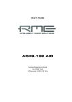
MADI.BRIDGE
User‘s Manual
Version 1.0

Copyright
All rights reserved. Permission to reprint or electronically reproduce any document or
graphic in whole or in part for any reason is expressly prohibited, unless prior written
consent is obtained from the DirectOut GmbH.
All trademarks and registered trademarks belong to their respective owners. It cannot
be guaranteed that all product names, products, trademarks, requisitions, regulations,
guidelines, specifications and norms are free from trade mark rights of third parties.
All entries in this document have been thoroughly checked; however no guarantee for
correctness can be given.
DirectOut GmbH cannot be held responsible for any misleading or incorrect
information provided throughout this manual.
DirectOut GmbH reserves the right to change specifications at any time without notice.
DirectOut Technologies® is a registered trademark of the DirectOut GmbH.
© DirectOut GmbH, 2015
page 2 of 32
Madi.Bridge Manual - Version 1.0

Table of contents
About This Manual
5
How to Use This Manual................................................................................ 5
Conventions................................................................................................... 5
CHAPTER 1: Overview
6
Introduction.................................................................................................... 6
Feature Summary........................................................................................... 6
How it works.................................................................................................. 6
Applications.................................................................................................... 7
CHAPTER 2: Legal issues & facts
8
Before Installing This Device.......................................................................... 8
Defective Parts/Modules .............................................................................. 8
First Aid (in case of electric shock)................................................................. 9
Updates........................................................................................................ 10
Conditions of Warranty................................................................................ 10
Intended Operation ..................................................................................... 10
Conformity & Certificates............................................................................ 11
Contact......................................................................................................... 11
Contents....................................................................................................... 12
CHAPTER 3: Installation
14
Installing the Device..................................................................................... 14
CHAPTER 4: Operation
18
Global Control............................................................................................... 18
Introduction.................................................................................................. 18
Signal Input / Output.................................................................................... 19
Signal Routing.............................................................................................. 19
Preset Memory............................................................................................ 20
Device Lock.................................................................................................. 22
Servicing / Remote Control.......................................................................... 23
CHAPTER 5: Troubleshooting and Maintenance
24
Troubleshooting............................................................................................ 24
Maintenance................................................................................................. 24
CHAPTER 6: Technical Data
26
Index27
Madi.Bridge Manual - Version 1.0
page 3 of 32

This page is left blank intentionally.
page 4 of 32
Madi.Bridge Manual - Version 1.0
About This Manual
About This Manual
How to Use This Manual
This manual guides you through the installation and operation of the device.
Use the Table of Contents at the beginning of the manual or Index Directory at the
end of the document to locate help on a particular topic. You can access more
information and latest news by visiting on the DirectOut website at
www.directout.eu.
Conventions
The following symbols are used to draw your attention to:
TI P S !
indicate useful tips and shortcuts.
N OT E S !
are used for important points of clarification or cross references.
WA R N I N G S!
alert you when an action should always be observed.
Madi.Bridge Manual - Version 1.0
page 5 of 32
CHAPTER 1: Overview
CHAPTER 1: Overview
Introduction
Welcome to MADI.BRIDGE, DirectOut’s solution for easy and elegant routing and
switching of up to 8 MADI signals. It features six coaxial (BNC) and two optical
(SC) MADI I/Os to link between MADI devices from any manufacturer.
Recently updated and redesigned, it acts as a patchbay, signal distributor, signal
buffer and input selector all in one device.
Feature Summary
MADI Ports
2 x SC multi-mode connectors
6 x coaxial BNC connectors
MADI Formats
56/64 channel, 48k/96k Frame, bit-transparent
Sample Rates
44.1, 48, 88.2, 96, 176.4, 192 kHz +/-12.5%
Preset Memory
9 configuration presets
MIDI Port
2 x DIN connectors (In/Out) for remote control
USB Port
USB 2.0 port for firmware updates and remote
control.
Power Supply
This device is equipped with two wide range power
supplies (84 V to 264 V AC / 47 Hz to 63 Hz / safety
class 1)
How it works
The input signal of each input port is gained and reclocked. Each port features push
buttons to select and a segment display to monitor the signal source (port number)
for it’s output. The input signal is not altered and processed bit-transparent to the
desired output. So even proprietary formats can be handled smoothly.
User definable presets can be used for fast configuration changes.
A 64 dot matrix allows to preview a preset or offers a quick overview about the
current routing setup.
To prevent accidental changes the device can be locked against remote or local
operation.
page 6 of 32
Madi.Bridge Manual - Version 1.0
CHAPTER 1: Overview
Applications
MADI.BRIDGE can be used for distributing, converting, selecting and reclocking
MADI signals.
Typical applications include:
• signal distribution
• input selection
• conversion between coaxial and optical and vice versa
• reclocking (‘signal refresh’)
• ...
Scheme
Port 1
Port 2
Port 3
Port 4
Port 5
Port 6
Port 7
Port 8
Madi.Bridge Manual - Version 1.0
Output
Selection
Port 1
Output
Selection
Port 2
Output
Selection
Port 8
page 7 of 32
CHAPTER 2: Legal issues & facts
CHAPTER 2: Legal issues & facts
Before Installing This Device
WAR NING!
Please read and observe all of the following notes before installing
this product:
• Check the hardware device for transport damage.
• Any devices showing signs of mechanical damage or damage from the
spillage of liquids must not be connected to the mains supply, or
disconnected from the mains immediately by pulling out the power lead.
• All devices must be grounded. The device is grounded through its
IEC power connections.
• All devices must be connected to the mains using the three-cord power
leads supplied with the system. Only supply electrical interfaces with the
voltages and signals described in these instructions.
• Do not use the device at extreme temperatures. Proper operation can
only be guaranteed between temperatures of 5º C and 45º C and a
maximum relative humidity of 80 %, non-condensing.
• The cabinet of the device will heat up. Do not place the device close
to heating sources (e.g. heaters). Observe the environmental conditions.
Defective Parts/Modules
WAR NING!
This device contains no user-serviceable parts. Therefore do not open the device.
In the event of a hardware defect, please send the device to your DirectOut
representative together with a detailed description of the fault.
We would like to remind you to please check carefully whether the failure is
caused by erroneous configuration, operation or connection before sending parts
for repair.
page 8 of 32
Madi.Bridge Manual - Version 1.0
CHAPTER 2: Legal issues & facts
First Aid (in case of electric shock)
WA R N I N G !
•
•
•
•
•
Do not touch the person or his/her clothing before power is turned off,
otherwise you risk sustaining an electric shock yourself.
Separate the person as quickly as possible from the electric power source
as follows:
-- Switch off the equipment.
-- Unplug or disconnect the mains cable.
Move the person away from the power source by using dry insulating
material (such as wood or plastic).
If the person is unconscious:
-- Check their pulse and reanimate if their respiration is poor.
-- Lay the body down and turn it to one side. Call for a doctor immediately.
Having sustained an electric shock, Always consult a doctor.
Madi.Bridge Manual - Version 1.0
page 9 of 32
CHAPTER 2: Legal issues & facts
Updates
DirectOut products are continually in development, and therefore the information
in this manual may be superseded by new releases. To access the latest
documentation, please visit the DirectOut website:
www.directout.eu.
This guide refers to firmware version 2.1
Intended Operation
The MADI.BRIDGE is designed for routing and distributing of digital audio signals.
In this context digital audio refers to a MADI signal (AES10).
Warning!
No compensation can be claimed for damages caused by operation of this unit
other than for the intended use described above. Consecutive damages are also
excluded explicitly. The general terms and conditions of business of DirectOut
GmbH are applied.
Conditions of Warranty
This unit has been designed and examined carefully by the manufacturer and
complies with actual norms and directives.
Warranty is granted by DirectOut GmbH over the period of two years for all
components that are essential for proper and intended operation of the device. The
date of purchase is applied for this period.
Consumable parts (e.g. battery) are excluded from warranty claims.
Warning!
All claims of warranty will expire once the device has been opened or modified, or
if instructions and warnings were ignored.
For warranty claims please contact the dealer where your device was acquired.
page 10 of 32
Madi.Bridge Manual - Version 1.0
CHAPTER 2: Legal issues & facts
Conformity & Certificates
CE
This device complies with the basic requests of applicable EU guidelines. The
appropriate procedure for approval has been carried out.
RoHS
(Restriction of the use of certain Hazardous Substances)
This device was constructed fulfilling the directive on the restriction of the use of
certain hazardous substances in electrical and electronic equipment 2002/95/EC.
WEEE
(Directive on Waste Electrical and Electronic Equipment)
Due to the directive 2002/96/EC for waste disposal this device must be recycled.
For correct recycling please dispatch the device to:
IMM Elektronik GmbH,
Leipziger Str. 32
09648 Mittweida
Germany
Only stamped parcels will be accepted!
WEEE-Reg.-No. DE 93924963
Contact
Sales:
DirectOut GmbH, Leipziger Str. 32, 09648 Mittweida, Germany
Phone: +49 (0)3727 99697-50 // Fax: +49 (0)3727 99697-52
www.directout.eu
Manufacturer:
IMM Elektronik GmbH, Leipziger Str. 32, 09648 Mittweida, Germany
Phone: +49 (0)3727 6205-0 // Fax: +49 (0)3727 6205-56
www.imm-gruppe.de
Madi.Bridge Manual - Version 1.0
page 11 of 32
CHAPTER 2: Legal issues & facts
Contents
The contents of your MADI.BRIDGE package should include:
• 1 x MADI.BRIDGE (19’’, 1 RU)
• 2 x power chord
• 1 x fixing unit for power plug
• 1 x Manual
To complete the delivery please download from the
DirectOut website: www.directout.eu
• USB Serial driver
page 12 of 32
Madi.Bridge Manual - Version 1.0
CHAPTER 2: Legal issues & facts
This page is left blank intentionally.
Madi.Bridge Manual - Version 1.0
page 13 of 32
CHAPTER 3: Installation
CHAPTER 3: Installation
Installing the Device
1. Open the packaging and check that the contents have been delivered
complete and undamaged.
NOT E !
The surface of the pane at the front panel is covered by a protection layer. The
foil can be peeled away from a corner. Avoid damaging the surface by using a
sharp or rough tool. The fingernail works perfect.
2.Fix the device in a 19’’ frame with four screws, or place it on a non-slip
horizontal surface.
WAR NING!
Avoid damage from condensation by waiting for the device to adapt to the
environmental temperature. Proper operation can only be guaranteed between
temperatures of 5º C and 45º C and a maximum relative humidity of 80%, noncondensing.
Ensure that the unit has sufficient air circulation for cooling.
3.Remove the protective cap from the optical MADI port(s) before use.
NOT E !
Retain the protective cap if the optical port is unused. This will protect against
soiling which can lead to malfunction.
4.Connect signal cable(s) for the MADI signals.
page 14 of 32
Madi.Bridge Manual - Version 1.0
CHAPTER 3: Installation
5.Optional: Connect an USB cable to the USB port for remote control or firmware updates. This requires the USB Serial driver (Windows) being
installed first. The driver and the installation instructions are available at
www.directout.eu.
6.Optional: Connect MIDI cables to the DIN connectors for remote control.
N OT E
The remote control software (Windows ®) will be available in a future release.
7. Using the power cord provided connect the PSUs to a matching power supply:
The left socket is switched by the power supply switch. The right socket will power up the device immediately when connected to the mains.
WA R N I N G !
This device must be connected to the mains using the three-cord power leads
supplied with the system. Only supply the voltages and signals indicated (84 V –
264 V).
Madi.Bridge Manual - Version 1.0
page 15 of 32
CHAPTER 3: Installation
8.Turn on the power switch:
While the device is booting the currently installed firmware is indicated in the front
panel displays - e.g. firmware version 2.1.
T IP !
Use the DirectOut Release Map to match your DirectOut device with the latest
firmware or software release.
Link: http://www.directout.eu/upload/dokumente/dotec_release_map.pdf
NOT E !
To update the firmware an installed USB serial driver (Windows) and the Update
Tool are necessary. The software and the installation instructions are available at
www.directout.eu.
9.Installation of USB Serial driver
• download the USB Serial driver
• download the ‘Installation Guide for USB Control’
• follow the installation instructions in the ‘Installation Guide for USB Control’
T IP !
Keep any packaging in order to protect the device should it need to be dispatched
for service.
page 16 of 32
Madi.Bridge Manual - Version 1.0
CHAPTER 3: Installation
This page is left blank intentionally.
Madi.Bridge Manual - Version 1.0
page 17 of 32
CHAPTER 4: Operation
CHAPTER 4: Operation
Introduction
This chapter describes the basic operation of the device.
Note that throughout this manual, the abbreviation FS refers to sample rate or
sample frequency. So, when dealing with scaling factors, the following sample
rates can be written as:
• 44.1kHz or 48kHz = 1 FS
• 88.2kHz or 96kHz = 2 FS
• 176.4kHz or 192kHz = 4 FS
Global Control
The display on the front panel indicates the power supply. Power switch is on the
back panel:
Power
1 Switch*
Enable / disable power supply.
Power
2 x C13 socket*
Connect the power supply here (84 - 264 V AC).
* The left socket is switched by the power supply switch. The right socket will
power up the device immediately when connected to the mains.
NOT E !
The display indicates that a working power supply is connected to the power
supply unit. Note that an unlit display does not guarantee that the device is free of
voltage. To ensure that the device is completely disconnected from mains voltage,
the power chord(s) must be disconnected.
page 18 of 32
Madi.Bridge Manual - Version 1.0
CHAPTER 4: Operation
Signal Input / Output
The device is equipped with six BNC coaxial (75 Ω) and two SC optical MADI ports.
2
1
2
1
BNC OUT / IN
port 1 to 6
2 x BNC socket (coaxial)
OUT: MADI output (64 ch), connect for MADI
output signal here.
IN: MADI input (64 ch), connect MADI input
signal here.
SC OUT / IN
port 7 & 8
2 x SC socket (optical)
OUT: MADI output (64 ch), connect for MADI
output signal here.
IN: MADI input (64 ch), connect MADI input
signal here.
Signal Routing
Each MADI output port is fed by one of the eight input ports. Push buttons for
each port allow to select the output source which is monitored by the individual
segment display.
INPUT
port 1 to 8
SELECTION
port 1 to 8
Segment display (green) indicates the
input source for the MADI output.
Values:1 to 8= port 1 to 8
0
= no source selected (mute)
The decimal point indicates that the source
selection differs from the selected preset.
Push buttons (up / down) to alter the
selection of the input source.
up = increasing value
down= decreasing value
A change will have immediate effect at the
signal output.
The active signal routing is stored in the device and recalled after power cycle.
Madi.Bridge Manual - Version 1.0
page 19 of 32
CHAPTER 4: Operation
Preset Memory
Different signal routing scenarios can be stored into presets. Before recalling a
preset a 64 dot matrix shows a preview of the routing. This allows to navigate
through all presets without changing anything at this time.
PRESETS
Segment display (red) indicates the
input source for the MADI output.
Values:1 to 9 =preset 1 to 9
0
=all outputs mute (read-only)
empty=display monitors the active routing
The decimal point indicates that the preset
selection differs from the active signal routing.
SELECTION
Push buttons (up / down) to navigate
the preset memory.
up = increasing value
down= decreasing value
STORE
Push button to overwrite a preset.
Press and hold > 2 s to store the active signal
routing into the displayed preset.
The decimal point will disappear.
RECALL
Push button to recall a preset.
Press and hold > 2 s to overwrite the current
signal routing with the signal routing that is
previewed in the dot matrix.
NOT E
In the segment displays the decimal point adjacent to the number indicates, that
the displayed information differs from the current and active preset. So a RECALL
would change the signal routing at the outputs.
page 20 of 32
Madi.Bridge Manual - Version 1.0
CHAPTER 4: Operation
DOT Matrix
The dot matrix is useful:
• to preview stored presets before recalling them
• to monitor the active signal routing, when preset memory is set to none (empty display)
The red dots mark a 1:1 routing; i.e. output and input signal are identical.
1
2
3
4
5
6
7
8
Individual signal routing:
output 1 < input 3
output 2 < input 2
output 3 < input 8
output 4 < input 5
output 5 < input 4
output 6 < input 6
output 7 < input 1
output 8 < input 8
1
2
3
4
5
6
7
8
Distributing signals:
output 1 to 4 are fed with signal of input port 2
output 5 to 8 are fed with signal of input port 4
1
2
3
4
5
6
7
8
1:1 routing:
output and input signals are identical each
OUTPUTS
I
N
P
U
T
S
1
2
3
4
5
6
7
8
OUTPUTS
I
N
P
U
T
S
1
2
3
4
5
6
7
8
OUTPUTS
I
N
P
U
T
S
1
2
3
4
5
6
7
8
N OT E
A 1:1 routing may cause a feedback loop at the connected device.
Madi.Bridge Manual - Version 1.0
page 21 of 32
CHAPTER 4: Operation
Device Lock
The device settings can be locked against unwanted modification.
Both disable of local access and disable of remote access are available individually.
LOCK
KEYS
Push button to enable / disable local lock.
Press to lock / unlock the front panel.
LOCK
KEYS
LED (red), indicates the lock state of the
front panel.
OFF = lock inactive
ON = lock active
LOCK
REMOTE
Push button to enable / disable remote
lock.*
Press to lock / unlock the remote access.
LOCK
REMOTE
LED (red), indicates the lock state of the
remote access.*
OFF = lock inactive
ON = lock active
* Remote access will be available with a future release.
page 22 of 32
Madi.Bridge Manual - Version 1.0
CHAPTER 4: Operation
Servicing / Remote Control
MIDI
The MIDI I/O is provided for remote control* of the device. Since the input
receives control data and the output sends status information of the device, both
connections are required for remote control.
MIDI
OUT / IN
2 x DIN 5-pin connector
OUT: MIDI output, connect for MIDI output signal here.
IN: MIDI input, connect MIDI input signal here.
USB
The USB port is used for firmware updates and remote control* of the device.
USB
USB 2.0 socket (Type B)
Connect here for firmware updates and remote
control.
* Remote access will be available with a future release.
Madi.Bridge Manual - Version 1.0
page 23 of 32
CHAPTER 5: Troubleshooting and Maintenance
CHAPTER 5: Troubleshooting and Maintenance
Troubleshooting
To identify a possible defect with the device please consult the following table.
If the fault cannot be resolved using these instructions, please contact your local
DirectOut representative or visit support.directout.eu.
Issue
Possible reason
Solution
Device doesn’t
work.
Power supply is
broken.
Check that the power supply switch
is on, that the device is connected to
the power supply and that the socket
is working. Defective fuses must be
exchanged by qualified service personal
only.
Optical port does
not work.
Optic is dirty.
Use an air supply to carefully remove any
dust.
Never use objects for cleaning.
No signal at the
output port.
Connections (input /
output) are mixed up.
Check the connections and change the
cables if necessary.
Check the routing matrix.
No signal at the
output port.
Signal cable defective.
Exchange the signal cable.
MADI signal at the
input is not stable.
Signal source is
defective
or
bad signal condition
(Jitter > 1 ns) - e.g.
due to exceeded
length or bad
screening attenuation
of signal cable.
Change the source
or
use appropriate cables.
Maintenance
To clean the device, use a soft, dry cloth. To protect the surface, avoid using
cleaning agents.
NOT E !
The device should be disconnected from the power supply during the cleaning
process.
page 24 of 32
Madi.Bridge Manual - Version 1.0
CHAPTER 5: Troubleshooting and Maintenance
This page is left blank intentionally.
Madi.Bridge Manual - Version 1.0
page 25 of 32
CHAPTER 6: Technical Data
CHAPTER 6: Technical Data
Dimensions
• Width 19’’ (483 mm)
• Height 1 RU (44.5 mm)
• Depth 7.8’’ (200 mm)
• Weight about 2 kg
Power Consumption
• 15 W
Power Supply
• 2 x C13 sockets
• 84 V - 264 V AC / 47 Hz - 63 Hz / Safety class 1
Environmental Conditions
• Operating temperature +5°C up to +45°C
• Relative humidity: 10% - 80%, non condensing
MADI Ports SC optical (2)
• 2 x SC socket FDDI (input / output)
• ISO/IEC 9314-3
• Wave length 1310 nm
• Multi-Mode 62.5/125 or 50/125
MADI Ports BNC coaxial (6)
• 12 x BNC socket (input / output)
• Impedance: 75 Ω
• 0.3 V up to 0.6 V (peak to peak)
Sample Rate
• 30 - 50 kHz @1 FS
• 60 - 100 kHz @2 FS
• 120 - 200 kHz @4FS
MADI Format (I/O)
• 48k Frame, 96k Frame
• 56 channel, 64 channel
MIDI (I/O)
• 2 x DIN 5-pin connectors
• Optocoupled, ground-free input
• MIDI Thru functionality
USB
• 1 x USB socket (Type B)
• for firmware updates and remote control
page 26 of 32
Madi.Bridge Manual - Version 1.0
Index
Index
C
Conformity & Certificates
CE......................................................... 11
RoHS.................................................... 11
WEEE................................................... 11
Contact..................................................... 11
Contents................................................... 12
Conventions................................................ 5
S
Scaling Factor........................................... 18
Scheme...................................................... 7
Signal Routing
distributing signals................................ 21
immediate............................................ 19
preview................................................. 20
Support..................................................... 24
D
Defective Parts/Modules............................ 8
Device Lock.............................................. 22
Dimensions............................................... 26
DOT Matrix............................................... 21
T
Troubleshooting........................................ 24
E
Environmental Conditions................... 14, 26
W
Warranty................................................... 10
U
Updates.................................................... 10
F
Feature Summary....................................... 6
Firmware.................................................. 16
First Aid...................................................... 9
I
Intended Operation................................... 10
Madi.Bridge Manual - Version 1.0
page 27 of 32
Notes
page 28 of 32
Madi.Bridge Manual - Version 1.0
Notes
Madi.Bridge Manual - Version 1.0
page 29 of 32
Notes
page 30 of 32
Madi.Bridge Manual - Version 1.0
Notes
Madi.Bridge Manual - Version 1.0
page 31 of 32
DirectOut GmbH
Leipziger Strasse 32
09648 Mittweida
Germany
T: +49-3727-99697-50
F: +49-3727-99697-52
www.directout.eu