
1
Timekeeper™
Users Manual
10/03/13
TimeKeeperTM F-Series Users manual
COPYRIGHT:
2000-2013 (C) by Alzatex, Inc.
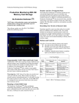
This software package is installed on many of the Alzatex TimeKeeperTM, products including timers and displays with
displays with 0.56” high digits to 36” high digits. The displays may have 1 to 16 digits and may have zero to 24
buttons. All models have remote inputs and/or a serial communication port. Optional remote button modules may be
used to control the timer/display.
Applications
• Production Monitoring and Production Control.
• Sporting Events of all kinds.
• Take-a-number Systems.
• Days since last accident display.
• Count down clocks.
• Public Speaking events.
• Master Clock Systems.
• And many others.
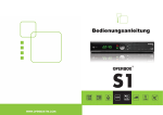
TMR221B TimeKeeperTM with 8 buttons, knob and LED
display.
KP219A-RF2 wireless keypad with 18 buttons and a
knob.
KP215A Remote Keypad with 8 buttons and a knob.
DSP606S Large LED display on a tripod.
VERSION=35
Page 1 of 26
www.alzatex.com
Timekeeper™
Users Manual
10/03/13
Features
This software supports the following features. Not all models will have all the features. See the list below describing
each of the individual models and the features supported.
•
Time of Day Clock.
The time of day clock displays hours, minutes and seconds in either military time or 12 hour AM/PM format. Also,
minutes and seconds only can be displayed.
•
Up/Down Count Timer.
The timer counts from 00.00 to 99.59 minutes, or from 00:00:00 to 99:59:59 hours. This timer can count seconds and
tenths or hundredths of seconds 00.00.00 to 99.99.99. The timer can be changed on-the-fly from time remaining to time
elapsed, while the timer is running. The timer has built in Green-Yellow-Red programmable warning times. A beeper
may be sounded at each of the warning times, at red only or be turned off.
•
Programmable Presets.
The timer can have up to 8 programmable presets. The values stored include the timer preset time, green and yellow
warning times, beeper mode, count up/down and run/stop status. The presets are stored in non-volatile memory, so they
are remembered even if the power is off and the battery is removed. The 8th preset is the power up preset.
•
Remote Display.
This unit can operate as a remote display slave to another Alzatex TimeKeeper TM, or may be remotely controlled by a
computer, Crestron, AMX system or PLC.
•
Take-A-Turn System.
This unit may also be used as a take-A-Turn system for NOW SERVING the next customer. The unit can be
configured with NEXT, PREVIOUS and RESET buttons. The unit also has remote inputs for external buttons.
Range 0 to 999,999.
•
Tallye Counter.
Wigits, machine operations, game scores or anything you may want to count may be counted. The unit can be
configured with UP, DOWN and RESET buttons. The unit also has remote inputs for external buttons or for connecting
to a machine for automatic operation. Range 0 to 999,999.
•
Remote Terminal.
This unit may be operated as a terminal to a PLC or other controller. Button presses from the Timekeeper TM are sent to
the PLC. The PLC sends display commands to the Timekeeper TM.
•
Serial data port.
Some models have RJ45 modular phone jacks on the rear of the unit. One jack is marked TX422 to transmit serial data
and another jack marked RX422 to receive serial data. Standard network cable is used. The Blue pair sends data in
RS422 format. The other pairs are used to send DC power from one device to another.
Some models have RJ11 modular phone jacks on the rear of the unit. One jack is marked TX to transmit serial data and
another jack marked RX to receive serial data. Four conductor modular phone cord is used to send data, power and
SYNC from one unit to another.
A standard RJ11 or RJ45 jack on the rear of the unit permits the timer to be connected to other timers and /or displays,
to remote displays or to a Crestron, AMX system, PC serial port or any other device having a RS232C serial port. The
baud rate is user-programmable from 1200 to 115,200.
•
Display Dimming.
The brightness of Remote displays may be controlled from the Timekeeper TM. This feature is useful for
daytime/nighttime use. The display dimming feature is available on specific models only.
VERSION=35
Page 2 of 26
www.alzatex.com
Timekeeper™
Users Manual
10/03/13
Timer reference guide.
The TimeKeeperTM TM Count Up/Down timer with Clock
The TimeKeeperTM TM Count Up/Down timer with Clock and Presets
Timer Mode (hh:mm:ss)
•
•
•
Press the Reset button to select timer mode.
Turn the Knob to set desired time. The Select button selects between setting hours, minutes and seconds.
Press the Start/Stop button to start the timer.
The Mode button selects between count-up and count-down modes. You may change between count-up and count-down
modes while the timer is running. In count-down mode, the timer stops when it reaches zero. In count-up mode, the
timer keeps running when the preset time is reached.
Press and hold the Mode button to select the desired beeper mode.
User Programmable Presets
•
•
•
•
•
•
Setup the timer preset time to the desired time.
Set the Green and Yellow Warning times the way you want them.
Also, select the desired count up/down mode and beeper mode.
If you want the preset to start the timer automatically, start the timer running.
Press and hold the desired Preset button to save the timer preset time, Yellow Warning and Yellow Blink times,
timer count up/down mode, beeper mode, special timer modes, timer run status, tallye counter preset value, and
tallye counter scale factor. When the display changes, the settings are stored.
To activate the Preset, a single button press will set the timer to the exact conditions that were saved.
Power Up Presets
•
•
•
•
•
•
•
•
•
Setup the timer preset time to the desired time.
Set the green and yellow warning times the way you want them.
Also, select the desired count up/down mode and beeper mode.
Press and hold the START button until the display changes. The display will show “FF ”.
Press and hold the RESET button until the display blinks to save the timer preset time, green and yellow warning
times, timer count up/down mode, beeper mode and special timer modes. When the display changes, the settings
are stored.
The next time the unit is powered up, these settings will be restored.
To delete the power up presets, set the hours, minutes and seconds to 00:00:00.
Press and hold the START button until the display changes. The display will show “FF ”.
Press and hold the RESET button until the display blinks. The next time the unit is powered up, the factory default
settings will be loaded.
Clock Mode
Press the Clock button to select clock mode.
The Clock or Select buttons select displaying 12 hour time, military time or seconds. In 12 hour mode, the PM
LED will be on for PM and off for AM.
Press and hold the Clock button to enter set time mode.
• Turn the Knob to set the hours.
• Press the Clock button again.
• Turn the Knob to set the minutes.
• Press the Clock button again to return to normal display, or other available settings, like seconds.
•
•
Special Timer Modes
While in the count down mode, when the timer reaches zero, it stops. Two other special timer modes are available.
Press and hold the Start button until the display changes. Turn the Knob to select the desired mode.
VERSION=35
Page 3 of 26
www.alzatex.com
Timekeeper™
•
•
•
•
Users Manual
10/03/13
Mode 0: (default) Stop when the timer reaches zero. In this mode, the timer stops when the elapsed time
reaches zero.
Mode 1: Red blink on timer zero. The red indicator blinks until the timer is reset.
Mode 2: Auto-Restart mode. In this mode, the timer automatically restarts counting down from the preset
value each time the timer reaches zero. The Auto-Restart mode works in both count up and count down
modes. The count up mode uses the count down timer preset time to determine when to reset the count up
timer back to zero and restart.
Mode 3: Change to count up when the timer reaches zero. In this mode, the timer changes to the count up
mode and starts counting up when the timer reaches zero.
Beeper Modes
The Timekeeper™ has five beeper modes: Single beep; Beep at each of the warning times; Pulsing beep until reset;
steady beep until reset, and beeper disabled. Press and hold the Mode button until the display changes. Turn the Knob
to select the desired beeper mode.
•
Mode 0: Beeper off.
•
Mode 1: A single beep when the timer reaches zero.
•
Mode 2: Beep at the warning times and at zero.
•
Mode 3: Continuous pulsing beep when the timer reaches zero. Pressing the Reset button stops the beep.
•
Mode 4: Continuous steady beep when the timer reaches zero. Pressing the Reset button stops the beep.
•
Mode 5: Not used. (Used with production TAKT timer only. See separate manual)
•
Mode 6: Not used. (Used with production TAKT timer only. See separate manual)
•
Mode 7: Beep when the timer is started. Also beeps when the timer reaches zero.
Red-Yellow-Green Display
•
•
•
•
•
•
•
•
•
•
•
•
•
The Green lamp comes on when the timer is started and remains on until the warning time is reached.
When the Yellow blink time is reached, the Green lamp goes off and the Yellow lamp blinks on and off
every second. The default Yellow blink time is 2 minutes (see table below) before the count down timer
reaches zero.
When the Yellow warning time is reached, the Yellow lamp remains on steadily. The default Yellow steady
time is 1 minute (see table below) before the count down timer reaches zero. Note that the yellow steady and
yellow blink times may occur in any order depending on the programmed setting. If they are set to the same
time, the yellow steady takes precedence.
When the timer reaches zero, the Red lamp comes on and the Yellow lamp goes off. In the count down mode,
the timer stops when the Red lamp turns on. In the count up mode, the timer keeps running after the lamp
turns Red.
Press the Reset button on the TimeKeeperTM to turn off the Red lamp.
you can set any desired yellow warning time. The green warning time will always be twice the yellow warning
time.
Setting minutes & seconds for the Blink Time
Press and hold the Select button until the screen reads “blnk” and then release the Select button. The current
blink time setting will appear.
Turn the Knob to the minute(s) setting desired.
Tap the Select button once and turn the knob to add seconds. (Tapping the Select button now toggles between
setting minutes and seconds.)
Tap the Reset button to return to the count-down time.
Setting minutes & seconds for the Warning Time
Press and hold the Select button until the screen reads “blnk.” Release the Select button and press and hold it
again until the screen reads “-lArm.” The current warning time setting will appear.
Turn the Knob to the minute(s) setting desired.
Tap the Select” button once and turn the knob to add seconds.
Tap the Reset button to return to the count-down time.
VERSION=35
Page 4 of 26
www.alzatex.com
Timekeeper™
Users Manual
10/03/13
NOTE: Different models present the warning times in different ways, but the basic behavior is the same, typically
displaying different colors for the warnings.
Total Time
Yellow Blink
Yellow Steady
Red
0:00-0:29
0:02
0:01
0:00
0:30-0:59
0:20
0:10
0:00
1:00-1:59
0:30
0:15
0:00
2:00-3:59
1:00
0:30
0:00
4:00-99:59
2:00
1:00
0:00
Timer Variations
Not all timer models can perform all the functions described in this document. Most timer models have a knob rather
than up/down buttons to set the time. Not all timer models have a beeper. Some minor variations exist between the
units, such as one unit has a Start button and another may have a Start/Stop button.
•
Count Down Timers have Start and Reset buttons.
•
Count Down Timers with Clock have Start, Reset and Clock buttons.
•
Count Up/Down Timers have Start, Reset, Mode and Select buttons.
•
Count Up/Down Timers with Clock have Start, Reset, Mode, Select, and Clock buttons.
•
Count Up/Down Timers with Presets have Start, Reset, Mode, Select, and one or more Preset buttons.
•
Count Up/Down Timers with Clock and Presets have Start, Reset, Mode, Select, Clock and one or more
Preset buttons.
•
Remote buttons can control the timers, and those remote buttons may have similar names but different
functions, such as buttons named “Start/Stop”, “Start/Pause”, or “Start”.
Timer Models
This manual supports the following Timekeeper™ models.
•
•
•
•
•
•
•
•
•
•
•
•
•
•
•
DSP017C-SM – Timer with four 0.56” high solid segment digits (surface mount; 4 buttons).
DSP017C-FM – Timer with four 0.56” high solid segment digits (flush mount; 4 buttons).
DSP221F-SM3, SM4, SM5, SM8, SM9 – Timer with four 0.56” high solid segment digits (surface mount;
3,4,5,8,9 buttons).
DSP221F-FM3, FM4, FM5, FM8 – Timer with four 0.56” high solid segment digits (flush mount; 3,4,5,8
buttons).
DSA216B16 – Timer with six 0.54” high solid segment alpha-numeric digits.
DSA256A – Timer with six 2-1/3” high solid segment alpha-numeric digits.
DSP106A – Timer with six 1” high solid segment digits.
DSP252E, DSP254E, DSP256E – Timer with 2-1/3” high solid segment digits.
DSP252E-TRI, DSP254E-TRI, DSP256E-TRI – Timer with 2-1/3” high tri-color solid segment digits.
DSP402B, DSP404B, DSP406B, DSP408B – Timer with 4” high individual LED digits.
DSP452A, DSP454A, DSP456A – Timer with 4” solid segment digits.
DSP502F, DSP503F, DSP504F, DSP505F, DSP506F, DSP508F – Timer with 5” high individual LED digits.
DSP602F, DSP604F, DSP606F, DSP608F – Timer with 6” high individual LED digits.
DSP702F, DSP703F, DSP704F, DSP706F, DSP708F – Timer with 7” high individual LED digits.
DSP1002F, DSP1003F, DSP1004F, DSP1005F, DSP1006F, DSP1008F – Timer with 10” high individual
LED digits.
Any of the units may have one or more optional buttons, as well as remote triggers/buttons. Some of the remote
keypads are listed below.
VERSION=35
Page 5 of 26
www.alzatex.com
Timekeeper™
•
•
•
•
•
•
•
•
•
•
•
•
Users Manual
10/03/13
KP212A – Keypad with 4 buttons, an RS422 jack and 2 optically isolated inputs in surface mount metal
enclosure.
KP213A – Keypad with one mushroom button, up to 4 small buttons, an RS422 jack and 2 optically isolated
inputs in an ABS plastic enclosure.
KP205A – Keypad with 8 buttons and a knob with RJ11 jacks mounted on a flush mount metal plate.
KP205A_GC – Keypad with 8 buttons and a knob, RJ11 jacks and 8 ground closure inputs mounted on a
flush mount metal plate.
KP215A – Keypad with 8 buttons and a knob, RS422 jacks and 2 optically isolated inputs mounted on a flush
mount metal plate.
KP219A – Keypad with 18 buttons and a knob with RS422 connectors in a metal enclosure.
KP219A-RF2 – Keypad with 18 buttons and a knob with built in wireless transmitter and one RS422 input in
a metal enclosure.
KP03A – Keypad with 4 user configurable buttons in a surface mount metal enclosure. Connects to the RSSR
input on the timer/display.
OC002A – Keypad with 2 user configurable buttons and 2 optically isolated inputs in a surface mount metal
enclosure. Connects to the RSSR input on the timer/display.
OC004B – Interface module with 4 optically isolated inputs in an ABS plastic enclosure. Connects to the
RSSR input on the timer/display.
You can provide your own buttons or connect your machine outputs directly to the RSSR inputs.
You can connect a PLC, Crestron, AMX or any other device with a serial port to control the various functions
of the Timekeeper™ timer/display.
Connecting multiple Timekeeper™s together
When multiple units are connected together, only one unit may become the controlling unit. The rest of the units
become remote displays.
•
•
•
•
•
The Timekeeper™ defaults to remote display mode at power up.
Be sure to connect the units up such that the controlling unit's transmit port is connected to the receive unit's
receive port.
Once a button is pressed, the controlling unit changes to clock/timer mode.
The controlling unit remains in timer mode until the power is turned off or a command is received that returns
it to remote display mode.
When connecting more than 2 units together, data on the transmit port of a remote display is echoed from the
receive port.
When two units are connected together, in a specific configuration. Either unit can control all of the functions.
•
Connect the transmit port of the first Timekeeper™ to the receive port of the second Timekeeper™.
•
•
Connect the transmit port of the second Timekeeper™ to the receive port of the first Timekeeper™.
Connect as many remote displays as you like to the first Timekeeper™.
VERSION=35
Page 6 of 26
www.alzatex.com
Timekeeper™
•
•
Users Manual
10/03/13
Configure the second Timekeeper™ to send key press commands. Set the “Time of day clock” setup
parameter to “CA”.
Now, either Timekeeper™ will operate all timer functions.
VERSION=35
Page 7 of 26
www.alzatex.com
Timekeeper™
Users Manual
10/03/13
Additional operating instructions
Standard Momentary Controls
•
•
•
•
•
•
•
RESET – Timer Reset
START – Timer Start/Stop
SELECT – Select between setting hours / minutes / seconds.
MODE – Change to Count Up, Count down.
CLOCK – Change to time of day clock mode.
PRESET – Recall stored settings.
HISTORY – Recall the 16 most recent counter or timer values (if this option is ordered).
Standard Press-and-Hold Controls
•
•
•
•
•
•
•
RESET – Store power up settings (if this option is ordered).
START – Set special timer mode or set button delay for remote inputs
SELECT – Set warning times or counter scale factor.
MODE – Change the beeper mode.
CLOCK – Set the time of day clock.
PRESET – Store settings.
HISTORY – Not used.
Clock Mode
Press the clock button to enter the clock mode. The Hours:Minutes:Seconds in 24 hour mode will be
selected.
•
Press the clock button again to display Clock Minutes:Seconds.
•
Press the clock button again to display Hours:Minutes:Seconds in 12 hour mode.
NOTE: On a timer with only 4 digits, only the hours and minutes will be displayed. On a timer with 6 digits, the hours,
minutes and seconds will be displayed.
•
The remote displays are updated once per minute with the correct time of day.
Device control Outputs
•
Optional Relay Control signal (BEEP). Activated whenever the timer reaches time zero. Beep relay.
Front panel Led definitions – TMR221 models only
Lower Left side
- ON=Beep on OFF=Beep off
Middle Left side
- ON=Count up OFF=Count down
Upper Left Side
- ON=PM
OFF=AM
Lower Right side
- ON=RED indicator, Time is up
Middle Right Side
- ON=YEL indicator, Yellow warning (“Wrap-it-up” time)
Upper Right Side
- ON=GRN indicator, Time is running
Above Clock Button - RED=Time set mode, GRN=No sync signal, BLINKING GRN=SYNC**
**NOTE: See section on SYNC for more details.
•
•
•
•
•
•
•
Dimming the display
Not supported on all models. The dimmer value in the range 0 to 99 provides several distinct brightnesses, where 0-3 is
the lowest brightness, and 96-99 is the highest brightness.
Note: Some models have 25 distinct levels while other models have only 4 or 10 distinct brightness levels.
VERSION=35
Page 8 of 26
www.alzatex.com
Timekeeper™
Users Manual
10/03/13
Remote Ground Closure Inputs
The remote ground closure inputs are user configurable. The default functions for these inputs
are described here. See the MSETUP configuration setting parameter for alternate functions for
these inputs.
The timer can be started, stopped or reset by remote control. Grounding the respective signal
activates the function. Typically the signals are grounded by pressing buttons on remote units.
Notice that inputs IN2 and IN3 are dual function. They operate differently depending on whether
the display is in timer mode or Tallye mode:
•
IN1 – Changes the display to timer mode. Starts the timer.
•
IN2 – In timer mode, stops the timer.
•
IN2 – In Tallye mode, decrements the tally count by the scale factor (default 1).
•
IN3 – In timer mode, resets the timer values to the initial preset values.
•
IN3 – In Tallye mode, sets the tally count to zero. Reset does not stop the timer.
•
IN4 – Changes the display to Tallye mode. Increments the tally count by the scale
factor (default 1).
The KP03A or OC002A keypads can be configured to use the inputs you specify. Remove the
rear cover of the KP03A or OC002A and configure the jumpers the way you desire.
Common configurations.
One common configuration used the keypad to control the Another common configuration used the keypad to
timer functions.
control the counter (Tallye) functions.
●
●
●
Button 1 = IN1 Timer Start.
Button 2 = IN2 Timer Stop.
Button 3 = IN3 Timer Reset to zero.
●
●
●
Typical Applications.
● Count up timer.
● Sporting events.
● Production timing.
● Event timing.
Button 1 = IN4 Counter Increment.
Button 2 = IN2 Counter Decrement.
Button 3 = IN3 Counter Reset to zero.
Typical Applications.
● Production counting.
● Cycle counting.
● Take-a-number systems.
● Score keeping.
Activating one of the inputs at a time
IN1 – If the unit is not in timer mode, puts the unit into timer mode. If the unit is in timer mode and the timer is not
running, starts the count up timer and increments the counter. If the unit is in timer mode and the timer is running,
freeze the display for several seconds to display the lap time. The count up timer keeps running. IN1 has the ability to
operate as a maintained or momentary ground closure. If IN1 is closed and held closed, the timer continues to run.
When IN1 is released, the timer pauses.
Alternate functions for IN1. See the MSETUP configuration parameter for enabling the selected function.
● START_LAP_UTMR. Triggering IN1 starts the timer. Triggering IN1 while the timer is running (the timer
continues to run) freezes the display for several seconds to display the lap time.
● RUN_PAUSE_TMR. Triggering IN1 starts the timer. Triggering IN1 while the timer is running pauses the
timer.
● RESET_START_TMR. Triggering IN1 resets and starts the timer. Triggering IN1 while the timer is running
resets and starts the timer again.
● RESET_START_STOP_TMR. Triggering IN1 resets and starts the timer. Triggering IN1 while the timer is
running stops the timer.
VERSION=35
Page 9 of 26
www.alzatex.com
Timekeeper™
Users Manual
10/03/13
IN2 – If the unit is in timer mode and the timer is running, stops the count up timer. If the timer is stopped, displays
the lap time for the previous lap or displays the time from the previous run. If the unit is in counter mode, decrements
the counter.
IN3 – If the unit is in timer mode, resets the count up timer to zero. If the timer is running, it continues to run from
zero. If the unit is in counter mode, resets the counter to zero.
Alternate functions for IN3. See the MSETUP configuration parameter for enabling the selected function.
● RESET. Triggering IN3 resets the timer.
● RECALL stored setting. Triggering IN3 recalls stored setting 1.
● IN3 has the ability to operate as a maintained or momentary ground closure. If IN3 is closed and held closed,
the timer continues to run. When IN3 is released, the timer pauses.
IN4 – If the unit is not in counter mode, put the unit into counter mode. If the unit is already in counter mode,
increment the counter.
Activating more than one of the inputs at a time (LEGACY mode)
These functions operate in legacy mode only. These functions are disabled if the MSETUP setting is not in legacy
mode.
IN1,IN2 – Run-Pause mode. If the unit is not in timer mode, puts the unit into timer mode. If the unit is in timer
mode and the timer is not running, starts or continues the count up timer and increments the counter. If the unit is in
timer mode and the timer is running, pauses the timer.
IN1,IN3 – Reset and Start, Stop mode. If the unit is not in timer mode, puts the unit into timer mode. If the unit is in
timer mode and the timer is not running, resets, then starts the count up timer and increments the counter. If the unit is
in timer mode and the timer is running, stops the timer.
IN1,IN2,IN3 – Two lap mode. Reset and Start, Lap Display, Stop mode. If the unit is not in timer mode, puts the unit
into timer mode. If the unit is in timer mode and the timer is not running, resets, then starts the count up timer and
increments the counter. If the unit is in timer mode and the timer is running, freezes the display for several seconds to
display the lap time. The count up timer keeps running. If the unit is in timer mode and the timer is running and the lap
time was displayed once, stops the timer.
IN3,IN4 – Sets the counter to the last preset value. Turn the Knob to set the timer preset value. The Select button
selects between setting the upper, middle or lower set of counter preset values. Generally this function occurs by
pressing the remote Counter Up and Counter Reset buttons at the same time.
IN1,IN4 – Beep the horn. Activates the beeper.
IN2,IN3 – Manually select the Red-Yellow-Green indicator. Each press cycles the Red or Yellow or Green indicator
on or turns all three indicators off.
Optional: This configuration may be enabled by ordering the USE_BTN4_MANUAL_RYG option.
IN4 – Manually select the Red-Yellow-Green indicator. Each press cycles the Red or Yellow or Green indicator on or
turns all three indicators off.
Remote command “KPJ – Manually select the Red-Yellow-Green indicator. Each press cycles the Red or Yellow or
Green indicator on or turns all three indicators off.
Optional: This configuration may be enabled by ordering the USE_BTN3_IS_RECALL1 option.
IN3 – Recalls stored setting 1. Whatever settings that are stored into stored setting 1 are loaded.
VERSION=35
Page 10 of 26
www.alzatex.com
Timekeeper™
Users Manual
10/03/13
Button Delay on remote inputs
In some situations it is best to ignore inputs for some period of time after the initial triggers.
Some examples:
•
In a horse race, a horse starts a timer by crossing a photo beam, but then its tail might generate an extraneous
trigger as it also crosses the beam.
•
Counting clear CD cases using a photo beam, which may incorrectly detect reflections or transparent portions
of the CD case as additional unit counts.
•
At the start of a race, a photo beam detects the large engine on a drag racing “funny car”, but then the opening
behind the engine allows it to generate a false trigger between the engine and the firewall that follows.
If you set the delay to 2.3 seconds, the respective input is ignored for 2.3 seconds after the initial trigger.
To change the button delay:
•
Press and hold the Test button.
•
Within 1 second, press the Test button eight more times to select the button delay for IN1. The display will
show "1-00".
•
Turn the Knob to change the selected button delay value.
•
Press the Select button to advance to the button delay for IN2. The display will show "2-00".
•
Turn the Knob to change the selected button delay value.
•
Press the Select button to advance to the button delay for IN3. The display will show "3-00".
•
Turn the Knob to change the selected button delay value.
•
Press the Select button to advance to the button delay for IN4. The display will show "4-00".
•
Turn the Knob to change the selected button delay value.
- OR •
Wait 3 seconds, then press the Test button successively to select the desired button delay configuration
parameter.
•
To exit, press any button that changes the display mode or turn the power off and then on again.
The new values are stored in permanent memory. When the power is turned off and on, the values will be remembered.
Counter mode
This unit contains a counter with a range of 0 to 999999
Trigger the counter remote input (IN4) to increment the counter. Trigger the counter remote input (IN3) to decrement
the counter. Trigger the counter remote input (IN2) to reset the counter.
Setting Counter scale factors
When the scale factor is 1, each trigger of the counter remote input (IN3) increments or decrements the count by 1. For
example, it may be better to count by lots or cases of product. If the lot size is 75, set the scale factor to 75. Each
trigger of the Tallye input will count in lots of 75.
To set the scale factor:
• Press the Counter Up button (input IN4) to select the counter mode.
• Press and hold the Select button until the display changes.
• Turn the Knob to set the lower two digits (xx00-xx99)
• Press the Select button again.
• Turn the Knob to set the upper two digits (00xx-99xx)
These settings can be saved into EEPROM by pressing and holding the stored settings button.
VERSION=35
Page 11 of 26
www.alzatex.com
Timekeeper™
Users Manual
10/03/13
A momentary press of the stored settings button will recall the saved values.
Counter preset value for counter count down mode
Connect Inputs IN3 and IN4 together to the same button. Each time the button is pressed, the counter is loaded with the
preset value.
Each time the IN2 (count down) input, the count is decremented by the scale scale factor amount,
To load a preset value into the counter, perform the following steps:
Press the counter UP/Reset input IN3,IN4 to select the counter mode.
Turn the knob to set the middle two digits (xx00xx-xx99xx)
Press the select button again.
Turn the knob to set the upper two digits (00xxxx-99xxxx)
Press the select button.
Turn the knob to set the lower two digits (xxxx00-xxxx99)
•
•
•
•
•
•
Historical data capture
The most recent 16 events are captured and saved into EEPROM. Three types of events are captured:
•
•
•
The timer value is captured if the unit is in the timer mode. The timer display must be in count up mode. Each
time the count up timer is reset to zero, the value in the display is stored into the history EEPROM memory.
The counter value is captured if the unit is in the counter mode. Each time the counter is reset, the value in
the display is stored into the history EEPROM memory.
The score value is captured if the unit is in the score keeper mode. Each time the score is reset, the value in
the display is stored into the history EEPROM memory.
To display the contents of the history memory, press the History button. Each press of the History button will display
successively older entries in memory. When the end of the history memory is reached, the display will
Show "------". Timer entries will have decimal points every two digits. Counter entries will not have any decimal
points.
VERSION=35
Page 12 of 26
www.alzatex.com
Timekeeper™
Users Manual
10/03/13
Remote Display mode
The remote display mode displays alphanumeric characters received on the serial port.
Alphanumeric character on Seven-Segment LED Displays
Due to the limitations of seven-segment LEDs, certain displays replace some alphabetic characters by a strange
character. Those replaced characters (both upper and lower case) for those types of displays are: m, q and w.
Additionally, the “z” character on those displays appears as two parallel lines “||”, and the “k” character partially
appears “|-”. The remaining characters appear only in their upper or lower case form in order to remain identifiable on
the seven-segment LED displays.
In addition to alphanumeric characters, the seven-segment LED displays are also able to show the dash, space and
period characters (“-”, “ “, “.”). Any other characters not mentioned here may be ignored by the display, potentially
causing the entire message to be ignored.
VERSION=35
Page 13 of 26
www.alzatex.com
Timekeeper™
Users Manual
10/03/13
Rear panel buttons.
Your display may have none, one or two rear panel buttons. If your display has one rear panel button, it will be the
Test/Configuration button.
•
Press the Test/Config button to display one of several test patterns.
•
Press and hold the Test/Config button to enter the configuration mode.
If your display does not have any rear panel buttons. You will still be able to make configuration changes.
•
Press and hold the Start button until the display changes.
•
Press and hold the Start button again until the display changes.
•
You are now in the configuration mode.
If your display has two rear panel buttons, Button one will be the Test/Configuration button. Button two will be the
History button.
•
Press the Test/Config button to display one of several test patterns.
•
Press and hold the Test/Config button to enter the configuration mode.
•
Press the History button to display the history memory.
If your display has a built in battery and battery charger, in addition to the normal functions, these buttons will also
perform the power ON and power OFF functions of the display.
•
Press and hold the Power ON/Test/Config button to turn the power on.
•
Press and hold the Off/History button to turn the power off.
Testing the unit.
Pressing the Test button successively advances through each of several diagnostic tests. These tests verify the operation
of the unit. Each press of the test button selects on of the following displays.
•
•
•
•
Scrolling Hello Message.
Segment Test Pattern.
All segments ON.
Input signal test.
Scrolling Hello Message.
Press the Test button to display the scrolling "Hello" message. This message is also sent on the serial port. Observe that
the message “Hello” scrolls across the display every few seconds.
Segment Test Pattern.
Press the Test button again to display the segment test pattern sequence. Observe the display. The segments should
light in the sequence as described below.
segment a on;
segment a-b on;
segment a-b-c on;
segment a-b-c-d on;
segment a-b-c-d-e on;
segment a-b-c-d-e-f on;
segment a-b-c-d-e-f-g on;
segment a-b-c-d-e-f-g-dp on;
All segments ON test.
Press the Test button again to turn all segments on. Verify that all segments are lit. Also verify that either the decimal
points or colons are lit depending on hardware configuration.
VERSION=35
Page 14 of 26
www.alzatex.com
Timekeeper™
Users Manual
10/03/13
Input signal test.
Press the Test button again to enable the input signal test. Press each of the buttons, Activate each of the remote inputs.
Turn the knob both clockwise and counterclockwise. Numeric values should appear on the display as shown in the
following table. Two dashes will scroll across the display along with some values depending on the state of the various
inputs.
Display Value
Description
A
Button 1
B
Button 2
C
Button 3
D
Button 4
E
Button 5
F
Button 6
G
Button 7
H
Button 8
0
Remote Input 1
1
Remote Input 2
2
Remote Input 3
3
Remote Input 4
4
Rotary Encoder Knob or button A
5
Rotary Encoder Knob or button B
6
50Hz/60Hz Sync signal detected.
7
32,768Hz Internal Oscillator detected.
Example display. If the display shows “--63A ”, this indicates that Button 1 is pressed, Remote Input 1 is active and
50Hz/60Hz Sync signal detected.
VERSION=35
Page 15 of 26
www.alzatex.com
Timekeeper™
Users Manual
10/03/13
Configuration and Setup.
The setup procedure is normally performed at the factory when you order the product. Occasionally, you may need to
make changes to the setup parameters. The setup parameters are summarized below.
•
•
•
•
•
•
•
•
•
The Timer Mode determines whether the display shows Days, Hours, Minutes, Seconds or 100ths of a
second.
The Mode Setup affects the function of the remote inputs and other system functions.
The Beep parameter affects the beep duration and beep mode.
The Unit Address is used when receiving communications from other devices. Range 0-31.
The Extended unit address has a range of 000 to FFF and is used with the serial communications port.
The SERCMD determines the number of digits transmitted on the serial communications port to a remote
display.
Time of day clock and remote control functions.
Baud rate of the serial communications port. 1,200 to 115,200.
Button Delay for the remote inputs IN1, IN2, IN3 and IN4.
There are several ways to change the configuration settings.
Use the Test/Config button on the rear of the unit.
• Use the Test/Config button on the rear of the unit. Press and hold the Test button until the display changes to
enter the setup mode.
• Within one second, press the Test button successively to advance through the various settings.
• Wait 2 seconds and press the Test button successively to change the value or Turn the knob to change the
value.
• Some models have a second button marked B. The B button will decrement the value, The Test button
increments the value.
Use the timer Start button on the front panel or remote keypad depending on model.
• If you have a remote key pad with a Timer Start button, to enter the setup mode, press and hold the Start
button until the display changes. The display will show “-0”.
•
•
•
Press and hold the Start button again until the display changes. The display will show “U..A”.
Press the Select button to step through the various settings.
Turn the knob to change the value.
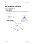
Select the timer display mode
This procedure selects whether the count up timer display shows hours, minutes, seconds or fractions of a second.
• Press and hold the Test button.
• Turn the Knob to change the selected configuration value.
- OR • Wait 3 seconds, then press the Test button to increment the selected parameter. The display shows a value
representing the timer mode
•
VERSION=35
Page 16 of 26
www.alzatex.com
Timekeeper™
Mode
Users Manual
Count Down
Count Up
8 Digit Display
Count Up
6 Digit Display
10/03/13
Count Up
4 Digit
Description
Knob defaults to setting seconds for modes 1, 2 and 2.
u..0
SS SS SS
SS.SS.SS.FF
SS SS.FF
SS.FF
Seconds .100ths
u..1
SS SS SS
SS SS SSS.F
SS SSS.F
SSS.F
Seconds .Tenths
u..2
SS SS SS
SS SS SS SS
SS SS SS
SS SS
Seconds
Knob defaults to setting hours for modes E, J and K.
Knob defaults to setting days for mode L.
Knob defaults to setting minutes for other modes.
u..3
MM MM:SS
MM MM:SS.FF
MM:SS.FF
SS.FF
Minutes :Seconds .100ths
u..4
MM MM:SS
MM MMM:SS.F
MMM:SS.F
M:SS.F
Minutes :Seconds .Tenths
u..5
MM MM:SS
MM MM MM:SS
MM MM:SS
MM:SS
Minutes :Seconds
u..6
MM MM:SS
MM MM MMM:S MM MMM:S
MMM:S
Minutes :Tens of Seconds
u..7
MM MM MM
MM MM MM
MM
MM MM MM
MM MM
Minutes
u..8
HH:MM:SS
HH:MM:SS.FF
MM:SS.FF
MM:SS.FF
Hours :Minutes :Seconds .
100ths
u..9
HH:MM:SS
HHH:MM:SS.F
H:MM:SS.F
M:SS.F
Minutes :Tens of Seconds
u..A
HH:MM:SS
HH HH:MM:SS
HH:MM:SS
MM:SS
Hours :Minutes :Seconds
u..b
HH:MM:SS
HH HHH:MM:S
HHH:MM:S
H:MM:S
Hours :Minutes :Tens of
Seconds
u..C
HH HH:MM
HH HH HH:MM
HH HH:MM
HH:MM
Hours :Minutes
u..d
HH HH:MM
HH HH HHH:M
HH HHH:M
HHH:M
Hours :Tens of Minutes
u..E
HH HH HH
HH HH HH HH
HH HH HH
HH HH
Hours
u..F
HH:MM:SS
DD:HH:MM:SS
HH:MM:SS
MM:SS
Days :Hours :Minutes
:Seconds
u.10
HH:MM:SS
DDD:HH:MM:S
D:HH:MM:S
H:MM:S
Days :Hours :Minutes :ten of
Seconds
u.11
DD:HH:MM
DD DD:HH:MM
DD:HH:MM
HH:MM
Days :Hours :Minutes
u.12
DD:HH:MM
DD DDD:HH:M
DDD:HH:M
D:HH:M
Days :Hours :Tens of Minutes
u.13
DD:HH:MM
DD DD DD:HH
DD DD:HH
DD:HH
Days :Hours
u.14
DD:HH:MM
DD DD DDD: H
DD DDD: H
DDD: H
Days: Tens of Hours
u.15
DD DD DD
DD DD DD DD
DD DD DD
DD DD
Days
u.16
SS SS SS
SS SS S.TTT
S SS.TTT
S.TTT
Seconds. Thousandths of a
second
NOTE: When mode 15 is selected, the days timer rolls over at midnight.
.
•
To exit, press any button that changes the display mode or turn the power off and then on again.
VERSION=35
Page 17 of 26
www.alzatex.com
Timekeeper™
Users Manual
10/03/13
Select the MSETUP mode
This procedure selects whether the count up timer display shows hours, minutes, seconds or fractions of a second.
• Press and hold the Start button until display changes.
•
Within 1 second, press the Start button until the display changes (selects the MSETUP mode configuration
parameter). The display will show "L1".
• Turn the Knob to change the selected configuration value.
- OR • Wait 3 seconds, then press the Start button to increment the selected parameter. The display shows a value
representing the timer mode
The following table describes the various options. Multiple options can be selected by adding the respective numbers
together. The numbers are represented in ASCII HEX notation. Range 0, 1, 2, 3, 4, 5, 6, 7, 8, 9, A, B, C, D, E, F. For
example, 8 plus 2 = 10 or “A” in ASCII HEX notation.
L-Value
Description
L00
Default to timer to count down mode.
L01
Default to timer to count up mode.
L00
Remote input 1 is default configuration. See documentation on
remote inputs for details.
L02
Remote input 1 is START-LAP Up Timer. Both the split time and the
lap time is stored into the history memory.
L04
Remote input 1 is START-SPLIT Up Timer. Both the split time and
the lap time is stored into the history memory.
L06
Remote input 1 is RUN-PAUSE Up Timer
L08
Remote input 1 is RESET-START Timer.
L0A
Remote input 1 is RESET-START-STOP Timer.
L00
Remote input 3 is RESET timer.
L10
Remote input 3 is RECALL stored setting 1.
L20
Remote input 3 is COUNTER2.
L30
Remote input 3 is COUNTER23
L00
The Green indicator is on when the timer is started; The Red
indicator is on when the timer reaches zero.
L40
The Red indicator is on when the timer is started; The Green
indicator is on when the timer reaches zero.
Beeper duration setup
•
•
•
Press and hold the Test button.
Within 1 second, press the Test button two more times to select the beeper mode configuration parameter. The
display will show "-1".
Turn the Knob to change the selected configuration value.
- OR -
VERSION=35
Page 18 of 26
www.alzatex.com
Timekeeper™
•
•
•
Users Manual
10/03/13
Wait 3 seconds, then press the Test button successively to select the desired beeper duration.
The beep duration is represented as 1= 0.4 second; 2=0.8 second; 3=1.2 second; etc. Range: 0-7.
To exit, press any button that changes the display mode or turn the power off and then on again.
Unit Address setup
The display can be set up to respond to an address-specific command. The address-specific commands provide the
same functionality as the general commands, but allow control of which display unit will respond when several
displays are connected together. A unit can be set to one address within the range 0 through 9, and A through O. The
address range is 0 to 1F in ASCII HEX notation. See the programming manual for more details on using this address
command.
Example corresponding commands are "KA0n. The address range is 0 to 1F in ASCII HEX notation where 0= “KA0x;
10=”KA@x; 11=”KAAx and 1F=”KAOx.
Example:
Two units are connected to the same serial port. One unit is configured for address '0', and the other is configured as
address '1'. The first unit ('0)' responds to a "KA0H command, but not the second unit ('1'). The second unit ('1')
responds to a "KA1W command, but the first unit does not.
Example corresponding commands are "L0xxxx through "L9xxxx and "LAxxxx through "LOxxxx. The address range is
0 to 1F in ASCII HEX notation where 0= “L0xxxx; 10=”L@xxxx; 11=”LAxxxx and 1F=”LOxxxx.
Example:
Two units are connected to the same serial port. One unit is configured for address '0', and the other is configured as
address '1'. The first unit ('0)' responds to a "L0Hello command, but not the second unit ('1'). The second unit ('1')
responds to a "L1World command, but the first unit does not.
To configure the address for a unit:
•
Press and hold the Test button.
•
Within 1 second, press the Test button three more times to select the unit address configuration parameter.
The display will show "AAA ".
•
Turn the Knob to change the selected configuration value.
- OR •
Wait 3 seconds, then press the Test button to select the desired unit address.
•
To exit, press any button that changes the display mode or turn the power off and then on again.
Extended Unit Address setup
The display can be set up to respond to an address-specific command. The address-specific commands provide the
same functionality as the general commands, but allow control of which display unit will respond when several
displays are connected together. A unit can be set to one address within the range 0 through 9, and A through F. The
address range is 000 to FFF in ASCII HEX notation for a total of 4096 possible addresses.
Example corresponding commands are "A000 through "AFFF. The address range is 000 to FFF in ASCII HEX
notation. See the programming manual for more details on using this address command.
Example:
Two units are connected to the same serial port. One unit is configured for address '0', and the other is configured as
address '1'. The first unit ('0)' responds to a "A000 command, but not the second unit ('1'). The second unit ('1')
responds to a "A001 command, but the first unit does not.
To configure the address for a unit:
•
Press and hold the Test button.
VERSION=35
Page 19 of 26
www.alzatex.com
Timekeeper™
•
•
Users Manual
10/03/13
Within 1 second, press the Test button four more times to select the unit address configuration parameter. The
display will show "HHH ".
Turn the Knob to change the selected configuration value.
- OR •
•
Wait 3 seconds, then press the Test button to select the desired unit address.
To exit, press any button that changes the display mode or turn the power off and then on again.
Serial Data Output setup
•
•
•
Press and hold the Test button.
Within 1 second, press the Test button five more times to select the serial data output configuration parameter.
The display will show "EE ".
Turn the Knob to change the selected configuration value.
- OR •
•
•
Wait 3 seconds, then press the Test button successively to select the desired number of digits to output on the
serial port.
The most common values are 2 through 8 digits. This should be set to match the connected remote displays.
Range 0 to 15 digits.
To exit, press any button that changes the display mode or turn the power off and then on again.
Time of Day Clock and serial data output setup
•
•
•
Press and hold the Test button.
Within 1 second, press the Test button six more times to select the time of day clock setup configuration
parameter. The display will show "CCC".
Turn the Knob to change the selected configuration value.
- OR •
•
Wait 3 seconds, then press the Test button successively to select the desired time of day clock setup duration.
To exit, press any button that changes the display mode or turn the power off and then on again.
The following table describes the various options. Multiple options can be selected by adding the respective numbers
together.
Value
Description
C00
Default to the 24 hour mode when the clock button is pressed.
C01
Default to the 12 hour mode when the clock button is pressed.
C02
Default display is a time of day clock in 12 hour mode. Disables
sending DSP, "L0, “TY, or TME commands on the serial port.
C03
Default display is a time of day clock in 24 hour mode. Disables
sending DSP, "L0, “TY, or TME commands on the serial port.
C00
While in the time of day clock mode, with 4-digit displays, send
HH:MM or MM:SS (4 digit) DSP or "L0 commands on the serial
port.
C04
While in the time of day clock mode, always send HH:MM:SS (6
digit) DSP or "L0 commands on the serial port.
C08
Default to remote mode.
C0A
Remote Control Mode. This mode is used to remotely control another
timekeeper connected to this unit. Pressing a button on this unit
generates “KPn commands that are sent to a remotely connected
VERSION=35
Page 20 of 26
www.alzatex.com
Timekeeper™
Users Manual
Value
10/03/13
Description
timekeeper. The remote timekeeper sends RLY, DSP or “L0
responses to this unit.
C00
Send "Lnxxxx commands on the serial port. Where n is the unit
address.
C10
Send DSPxxxx commands on the serial port.
C02
Process "KPn commands locally.
C12
Do not Process "KPn commands locally. Echo "Kpn commands back
out on the serial port.
C20
90 second power off delay. When powered by DC, the display goes
dark when the timer is not running or no data is being received. When
powered by AC or receiving a 50/50Hz sync signal, this option has
no effect.
C40
All received serial data characters are echoed out on the transmit
serial port. This unit does not transmit RLY, DSP or “L0 commands.
Baud rate setup
•
•
•
Press and hold the Test button.
Within 1 second, Press the Test button seven more times to select the RS232 serial port baud rate. The display
will show "61".
Turn the Knob to change the selected configuration value. (Cannot be changed from a remote keypad)
- OR •
•
Wait 3 seconds, then press the test button to select the desired baud rate. The range is 0 to 7 corresponding to
0=1,200, 1=2,400, 2=4,800, 3=9,600, 4=19,200, 5=38,400, 6=56,800, 7=115,200 baud.
To exit, press any button that changes the display mode or turn the power off and then on again.
NOTE: Most Alzatex products default to 2,400 baud. The baud rate should be set to “b1” in most situations.
Button Delay setup for IN1, IN2, IN3 and IN4
The purpose of this setting is to eliminate false triggers from the timer start button accidentally being triggered twice.
For instance, if you are racing horses, The horses head starts the timer, but the swishing of the tail should be ignored. A
bicycle starts the timer, but the openings in the frame should be ignored. If you are counting CD cases, the case
increments the count, but the clear portions of the case should be ignored.
The RSSR port has 4 inputs. See the section on remote inputs for details of the function of these inputs.
•
•
•
Press and hold the Test button.
Within 1 second, Press the Test button eight more times to select the button delay setup. The display will
show "0-00".
Turn the Knob to change the desired button delay value.
- OR •
•
Wait 3 seconds, then press the test button to select the desired baud rate. The range is 0 to 99 corresponding to
0=No delay, 1=0.1 second, 2=0.2 second, 10=one second, 50=five seconds.
To exit, press any button that changes the display mode or turn the power off and then on again.
NOTE:.
Displaying the firmware version number
•
Press the Config button. As the button is being pressed, a 2 digit number will appear on the display. This is
the firmware version number.
VERSION=35
Page 21 of 26
www.alzatex.com
Timekeeper™
Users Manual
10/03/13
Remote time of day setting
When the time of day is being set, the TME command is generated when the time set mode is exited. This is useful
when setting the time of day in the remote displays. When multiple timers and/or displays are connected together, the
time of day information is automatically passed from the controlling unit to all the slave units.
It may be desirable for the remote units to display the time of day when not being used for other purposes.
To cause the remote units to remain in the time of day clock mode while the controller is disconnected from the system,
perform the following steps.
● Make sure the time of day clock is set correctly.
● Press the clock button to cause the time of day to appear in the display.
● Disconnect the controlling unit from the system.
● All the remote displays will display the time of day.
To cause the remote units to go dark while the controller is disconnected from the system, perform the following steps.
● Press the reset button to cause the timer or counter to appear in the display.
● Disconnect the controlling unit from the system.
● All the remote displays will display go dark after a few seconds.
Technical Description
This section contains information that might be useful for system designers, system integrators and installers.
Power up
When the unit is first powered up all the LEDs come on and the scrolling message "Hello” appears in the display.
NOTE: If the “Hello” message appears, but does not scroll, the firmware is a variation not described by this manual.
\
NOTE: If you have stored a power up preset, the Hello message will not appear.
Connectors
The TimerkeeperTM unit will have some or all of the following connectors. Refer to the data sheet for the specific model
for details.
•
RJ11 serial data connectors.
•
RJ11 ground closure input connector.
•
RJ45 serial data connectors.
•
Power Connector
RJ11 Serial Data Connectors
RJ11 accessory connectors:
•
RJ11 Receive Jack, marked “RX” or “IN”. This connector receives data from other units on DATA 1 and
transmits data on DATA 3.
•
RJ11 Transmit Jack, marked “TX” or “OUT”. This connector transmits data to other units on DATA 1 and
receives data on DATA 3.
•
The DATA 2 pin on the and RJ11 carries the 50/60Hz sync signal.
•
Using a 4 conductor modular cord, the RJ11-TX connector is typically used for transmit data. RJ11-RX
connector is typically used for receive data.
•
Using a 6 conductor modular cord, the RJ11-TX is typically used for transmit data on DATA 1 and receive
data on DATA 3. The RJ11-RX connector is typically used for receive data on DATA 1 and transmit data on
DATA 3.
VERSION=35
Page 22 of 26
www.alzatex.com
Timekeeper™
Users Manual
10/03/13
TM
Timekeeper Serial Data Input and Output on the RJ11 jacks
—
+12V
TX
Ground
60 Hz Sync
RX
—
+12V
RX
Ground
60 Hz Sync
TX
Use 6P6C Crossover Modular Cord
TM
with Timekeeper
RJ-14
(1) WH
(2) BK
(3) RD
(4) GN
(5) YL
(6) BL
Data 3
+12V
Data 1
Ground
Data 2
Data 4
Display
Use 6P6C Standard Modular Cord
with LED displays.
RJ11 Ground Closure Input Connector
RJ11 remote control timer RSSR jack with ground closure inputs:
•
RJ11 Ground Closure Jack, marked “RSSR”, with lines described in this document as “IN1,IN2,IN3,IN4”. See
the connection diagram provided in the installation instructions for a particular unit. Buttons, readers, optical
couplers, photo beams, hall-effect sensors, or more line outputs may be connected to these inputs. This
connector also has an output to provide external power to operate external sensors.
TimekeeperTM Remote Ground Closure Inputs Setup as a Counter
Decr
Reset
Incr
—
+12V
Counter Decrement
Ground
Counter Reset
Counter Increment
IN 3
+12V
IN 1
Ground
IN 2
IN 4
RJ-14
(1) WH
(2) BK
(3) RD
(4) GN
(5) YL
(6) BL
Use 6P6C Crossover Modular Cord
TM
with Timekeeper
Display
Use 6P6C Standard Modular Cord
with LED displays.
Run/Lap
Pause
Reset
Timer Run/Lap
+12V
Timer Pause
Ground
Timer Reset
—
IN 3
+12V
IN 1
Ground
IN 2
IN 4
RJ-14
(1) WH
(2) BK
(3) RD
(4) GN
(5) YL
(6) BL
Use 6P6C Crossover Modular Cord
with TimekeeperTM
Display
Use 6P6C Standard Modular Cord
with LED displays.
VERSION=35
Page 23 of 26
www.alzatex.com
Timekeeper™
Users Manual
10/03/13
RS422 Serial Data Connectors (RJ45)
The TimerkeeperTM unit will have none, some or all of the following RJ45 connectors:
•
RJ45 Receive Jack, marked “RX422” or “IN”.
•
RJ45 Transmit Jack, marked “TX422” or “OUT”.
In the single channel configuration, There is a single RS422 data channel. The other 3 pairs carry power. If you do not
install the jumpers, then the Green pair is not used.
Ground
+ Power
Ground
Data P
Data N
+ Power
Ground
+ Power
(1)
(2)
(3)
(4)
(5)
(6)
(7)
(8)
WH/OR
OR/WH
WH/GN
BL/WH
WH/BL
GN/WH
WH/BN
BN/WH
TimekeeperTM
Cat-5 Cable
Products that have a 2x6 pin jumper block
In the dual channel configuration, There are two RS422 data channels. One pair transmits data while the other pair
receives data. The other 2 pairs carry power.
•
•
The TX422 Jack will transmit data on the Data 1 pair and receive data on the DATA 2 pair
The RX422 Jack will receive data on the Data 1 pair and transmit data on the DATA 2 pair
Ground
+ Power
Data 2N
Data 1P
Data 1N
Data 2P
Ground
+ Power
(1)
(2)
(3)
(4)
(5)
(6)
(7)
(8)
WH/OR
OR/WH
WH/GN
BL/WH
WH/BL
GN/WH
WH/BN
BN/WH
TimekeeperTM
Cat-5 Cable
Products that have a 2x6 pin jumper block
The RJ45 connectors are configured as follows:
•
Pair 1 (Blue/White) is used for RS422 data transmission/reception.
•
Pairs 2,3,4 (Orange/White, Green/White and Brown/White) are used to carry 12VDC power.
•
In some cases, Pair 2 (Green/White) are used for data in the reverse direction. These units have special
configuration jumpers to change the function of pair 2.
VERSION=35
Page 24 of 26
www.alzatex.com
Timekeeper™
Users Manual
10/03/13
Power Distribution
All of the connectors described above have 12VDC power input/output so that if one Timerkeeper TM is powered, all are
powered. Keep in mind that larger displays require more power. The power supplies within a display unit has specific
limitations. DO NOT overload the power supply. If you are powering a larger number of displays, Alzatex provides a
KT6X422A or KT8X422A distribution module that permits multiple displays to be powered from a single source.
With the use of these distribution modules, an unlimited number of displays may be connected in a single system.
Some models have only RJ11 connectors, while other models have only RJ45 connectors. Alzatex provides a PS422A
module that can power up to 4 devices and converts from RJ11 to RJ45 interfaces. See the data sheet for details.
Alzatex also manufactures serial interface modules to convert data from RS422 or RJ11 to RS232C. These modules
also have a built in power supply for powering timers and/or displays.
•
The PS1DB9B interface adapter converts RJ11 data to RS232C.
•
The PS422DB9A interface adapter converts RJ45 (RS422) data to RS232C.
See the connection diagram provided in the installation instructions for a particular unit.
● The power supply in the DSP017 and DSP221 series can drive up to a 0.75A load.
● The power supply in the larger sized displays/timers can drive up to a 2A load.
● Larger loads require a distribution module. Each distribution module can drive up to a 5A load when the
12VAC50VA wall transformer is used.
● Larger loads require a distribution module. Each distribution module can drive up to a 9A load when the
SYM04 power supply is used.
Beeper and/or Relay Output
See the specific relay output applications on how these optional configurations are used:
•
Run Relay. Some models have an NPN ground closure output. Specific models may be equipped with a relay
with 2.5A or 5A dry contacts. The RUN relay option must be specified when ordering.
•
Beep Relay. Some models have an NPN ground closure output. Specific models may be equipped with a relay
with 2.5A or 5A dry contacts. The BEEP relay option must be specified when ordering.
•
Beeper. Instead of or in addition to the relay, One or more beepers or loud sounders may be installed. The
specific Beeper/Sounder option must be specified when ordering.
Wireless Communication
A wireless transceiver may be connected to most models. Any number of timers and displays may be connected
together using wireless communication.
•
The 2.4GHz wireless module is accepted in most countries.
•
The 900MHz wireless module provides a longer range. (USA only)
A wireless receiver for a hand held keyfob may be connected to most models.
•
Timer. The 3 button key chain transmitter provides timer start, stop and reset.
•
Counter. The 3 button key chain transmitter provides counter increment, decrement and reset.
DC power status checking and the 50/60Hz SYNC signal
The unit will accept either 50Hz or 60Hz line frequencies. It will automatically detect which line frequency is being
received. This feature only applies to models that the 50/60 Hz SYNC feature.
The AC/DC power status can be checked by observing the 60Hz SYNC signal. An oscilloscope or multi-meter will
help when observing this signal. This signal will have one of the following states.
VERSION=35
Page 25 of 26
www.alzatex.com
Timekeeper™
•
•
•
•
Users Manual
10/03/13
Steady logic low indicates battery operation.
Steady logic high indicates DC power applied.
Pulsing at the 60 Hz rate indicates 60 Hz AC power applied.
Pulsing at the 50 Hz rate indicates 50 Hz AC power applied.
Clock SYNC signal status monitoring system.
An indicator that visibly signifies whether or not the 50/60Hz sync is being received. In the timer mode, the PM LED
is on permanently if no 50/60Hz sync is detected.
While in clock mode, the center colon reflects the same information as the clock LED. The clock LED will be used to
indicate the status of the clock SYNC signal. When the clock LED is off, the unit is in the timer or tally mode.
No sync signal is being received.
•
•
When the clock LED is on steadily, no sync signal is being received.
In this mode the clock is the least accurate. In this mode, the clock has an accuracy of the internal crystal.
The 32KHz is generating the sync signal.
This is not available on all models.
•
The clock LED flashes once every 2 seconds.
•
When the clock LED is making very short flashes one per second, the internal 32KHz crystal is generating
the SYNC signal.
•
In this mode the clock is the much more accurate. In this mode, the clock has an accuracy of 20 parts per
million.
External 50hz sync has been detected.
•
•
•
The clock LED blinks on/off every 2 seconds.
When the clock LED is on for two seconds, then off for two seconds, the timer is receiving a SYNC signal
from a 50Hz AC line.
In this mode the clock is the most accurate. The clock is as accurate as the AC line frequency. In most
countries the accuracy is within five seconds per year.
External 60hz sync has been detected.
•
•
•
The clock LED blinks on/off once per second.
When the clock LED is on for one second, then off for one second, and continues to repeat this pattern, then
the timer is receiving a SYNC signal from a 60Hz AC line.
In this mode the clock is the most accurate. The clock is as accurate as the AC line frequency. In most
countries the accuracy is within five seconds per year.
Timekeeper™ wiring diagram examples are available in separate documents.
See the specific application note that best fits your application.
VERSION=35
Page 26 of 26
www.alzatex.com


![to a copy of the presentation! [ PDF 3659 kB ]](http://vs1.manualzilla.com/store/data/005993145_1-0ef1bf04b92f9350e985abe9a695cb4d-150x150.png)
