1
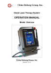
LASER THERAPY I.A.C.E.R. Srl MNPG179-00 09/01/15 CONTENTS INFORMATION ON THE OPERATING MANUAL........................................................ 4 TYPOGRAPHIC CONVENTIONS .................................................................................... 4 WARRANTY .......................................................................................................... 4 WARNINGS ........................................................................................................... 5 USE ...................................................................................................................... 6 MAINTENANCE ..................................................................................................... 7 INTRODUCTION TO THE TECHNOLOGY................................................................... 9 The evolution of light ................................................................................................. 9 The benefits of Laser therapy ..................................................................................... 9 PURPOSE .............................................................................................................10 INDICATIONS............................................................................................................. 10 SCOPE ....................................................................................................................... 10 COUNTERINDICATIONS............................................................................................. 11 DESCRIPTION OF THE EQUIPMENT .......................................................................11 INSTALLATION........................................................................................................... 11 CONNECTIONS .......................................................................................................... 11 START-UP and PROTECTION PASSWORD ................................................................. 12 DESCRIPTION OF THE EQUIPMENT .......................................................................13 USE OF THE MACHINE ..........................................................................................14 OPERATION ............................................................................................................... 14 PREPARATION OF THE PATIENT ............................................................................14 SELECTION OF PATHOLOGIES ...............................................................................15 SELECTION OF FREE PROGRAM.............................................................................15 END OF TREATMENT ............................................................................................16 OPERATIONAL ISSUES ..........................................................................................16 ELECTROMAGNETIC INTERFERENCE ......................................................................17 Annex A - PROTECTION OF THE ENVIRONMENT ...................................................... 18 Annex B – LABELSNO LABELS.................................................................................... 19 Annex D - ELECTROMAGNETIC COMPATIBILITY TABLES .......................................... 24 INFORMATION ON THE OPERATING MANUAL This operating manual is intended for: - the machine user; - the owner; - the supervisors; - the people responsible for handling; - the installers; - the operators; TYPOGRAPHIC CONVENTIONS Underlining is used to highlight parts of the document. NOTE Notes emphasize the importance of certain information. WARNING Warning messages appear before operations which must be carried out to avoid damage to the machine and/or its accessories. ! CAUTION ! The CAUTION messages concern operations or situations which, if not taken into account or carried out correctly, could cause problems for the user. - the maintenance technicians. This document provides information on the installation and correct use of the I-TECH LA8000/10000 laser therapy equipment. The operating manual must be considered part of the equipment and kept for future reference until final disposal of the equipment. The instruction manual must be kept available for reference near the machine and stored in the correct manner. The company cannot be held responsible in the following cases: - improper use of the machine; - use not in compliance with the specific domestic regulations in force; - incorrect installation; - power supply defects; WARRANTY IACER srl guarantees the quality of its equipment when it is used in compliance with the instructions provided in this manual, for a period of 24 months from the date of purchase. For the professional user, the warranty is valid for a period of 12 months from the date of purchase. Under the terms of the warranty, the company repairs or replaces products, at its own discretion, found to be defective. Under no condition is the equipment replaced in its entirety. The warranty does not cover malfunctions or damage attributable to: - unsuitable positioning, installation and commissioning; - incorrect use or use not in compliance with the requirements in this manual; - negligent or insufficient maintenance; - unauthorised modifications and repairs; - use of spare parts or materials not compatible with the model; - improper or unsuitable maintenance carried out by the user; - failure to observe the environmental specifications for the product; - unauthorised opening of the external casing; - failure to comply with some or all of the instructions provided; - unauthorised modifications and/or repairs; - exceptional events. - use of non-original accessories. Please contact the IACER srl company directly for any further information. The warranty is provided free of charge by the registered office of IACER srl. MNPG179-00 Pag. 4 In the event of a return, please follow the instructions on packing below and enclose a copy of the purchase receipt. - Before returning the machine in the event of a suspected malfunction, we recommend reading with care the chapters entitled MAINTENANCE and TROUBLESHOOTING: most problems can be attributed to insufficient maintenance or minor technical issues that the user can resolve easily. - Instructions on packing and returning the equipment: 1. disconnect the power cables and the connection cables for the handpieces, applicators, etc.; - 2. clean with care and disinfect all the accessories and parts of the machine that have been in contact with the patient. For obvious reasons of hygiene, and in the interests of the health of the technical staff (directive concerning safety at the workplace, T.U.S. (Consolidated Safety Act) 81/2008), any equipment that the admissions staff consider to be hygienically unsafe is not permitted; - - 3. disassemble the accessories and any mechanical supports; 4. reuse the original box and packaging materials; 5. enclose the Assistance Request Form with the product, stating the reasons for the request for revision and the type of fault or malfunction: this information will greatly facilitate the work of the technicians and ensure a faster service. WARNINGS - Recommendations: - - Read the entire operating manual. It is essential to wear protective glasses. Do not use the equipment near or on top of other equipment. If this is not avoidable, the operator must monitor the correct operation of the equipment. Do not use the equipment in the vicinity of flammable materials, solutions or gases, or in oxygen-rich environments, in order to avoid the risk of FIRE AND/OR EXPLOSION. - - - MNPG179-00 Assess and avoid the use of accessories or of any other parts that, during normal operation, could contain elements that might explode/ignite (e.g. absorbent cotton saturated with oxygen) on contact with the laser beam. CAUTION: to avoid the risk of electrocution, connect this equipment to an earthed power supply system. Even though no particular measures are required when installing the device, carefully insert the optical fibre in the socket of the panel of the I-TECH LA8000, making sure not to touch the end of the fibre with your fingers as this could dirty the laser input and prevent the correct flow of the laser beam, causing power losses and overheating between the connection of the tip and the I-TECH LA8000. After carefully inserting the optical fibre in the socket, turn the locking ring clockwise to the end of its stroke without forcing it. In any case, turn the locking ring to bring the reference mark on this parallel with the one on the socket of the optical fibre. If the laser tip of the I-TECH LA8000 needs to be disconnected, put the protective caps back on the tip of the optical fibre and on the panel socket of the device. This is very important to protect the delicate optical parts from dust and other dirt. When the I-TECH LA8000 is turned on, all the people in the room must wear suitable CE protective glasses. The customer is held responsible for any damage due to inadequate packaging. Keep the original packaging from the machine: you will need this in the event of a return. Do not use the equipment in areas where it could get wet. Check the connections carefully with reference to the instructions provided, before turning on the machine. Do not use accessories other than the original ones provided: non-original ones can damage the machine and render the warranty null and void. If any problems or difficulties arise during installation, please contact the technical assistance service at IACER srl. If using the same extension for the machine and other equipment, check that the total power consumption of the connected devices does not exceed the maximum permitted current for the type of cable, which should in any case not exceed 15 A. Recommendations concerning therapy are saved on the hard drive of the machine. These cannot be deleted or modified, but the parameters can be customised in the "Libero" (Free) section. It is not possible to recommend a specific number of sessions for an efficient Pag. 5 treatment because this depends on the amount of power used to treat the patient. The doctor must decide on the number of sessions for the patient according to the specific requirements involved, in order to guarantee effective treatment over time and conditions of absolute safety. - Routinely check the condition of the power cord and the cable connected to the handpiece/applicator: these must be neither damaged nor worn. - Assess the quantity and type of pigment of the skin of the patient. - Both the patient and the operator must wear protective glasses. - Do not direct the laser beam at the eyes or thyroid. USE - The laser radiation produced by the equipment is intrinsically dangerous: always wear protective glasses, do not direct the beam at unprotected eyes or at any optical instruments, and avoid exposing eyes to direct or diffused radiation. Before starting any treatment, both the operator and the patient must put on PROTECTIVE GLASSES. Insert the INTERLOCK key in order to run the machine. - DURING TREATMENT IN CONTINUOUS MODE, IT IS FORBIDDEN TO HOLD THE HANDPIECE - - STILL IN ONE POSITION. IT IS ESSENTIAL TO MOVE THE HANDPIECE TO SCAN THE TREATED of the laser into areas other than those to be treated. - glasses. Always avoid exposing eyes to direct or diffused radiation. - - This is a class A machine in terms of emissions. The machine is suitable for use in hospital and outpatient wards, taking into account however that it can cause interference with other electronic equipment in the immediate vicinity. Laser treatments must be carried out under the close supervision of the operator and with the patient fully conscious and able to provide feedback on the effects of the machine. IACER Srl cannot be held responsible for accidents due to a failure to observe this requirement. - Use of the controls, adjustments and procedures other than those specified in this operating manual can cause exposure to hazardous radiation. - The operator is responsible for checking that the emission head remains in contact with the affected area in order to prevent emission MNPG179-00 It is advisable to carry out treatment only when the machine is in perfect mechanical working order and the laser specifications are suited to the purpose (refer to the table of technical specifications). - Keep the handpiece in contact with the affected area during emission of the laser. After activating the handpiece by means of contact with the plates, avoid moving it towards or directing it at other areas. - NEVER DIRECT THE HANDPIECE AT PARTS OF THE BODY THAT ARE SENSITIVE TO LASER BEAMS, LIKE THE EYES. - DO NOT LOOK INTO THE BEAM OF THE HANDPIECE OR THE ONE DIRECTED OR REFLECTED DURING TREATMENT. - Always save each customised protocol with a different name in order to avoid confusion. Using the same name for two different protocols will result in both protocols being saved with the same name. - Never leave the device running unattended and always turn it off after use. - In order to avoid contamination of the work environment and/or of the people involved in its use, only use laser handpieces cleaned and disinfected with care AREA. - The laser radiation from the equipment is hazardous: always wear protective after the previous treatment. - In the interest of the patient's absolute safety, it is advisable to have the machine tested on a routine basis (a minimum of once every 2 years) by the manufacturer, IACER Srl. - It is strictly forbidden to use the device in the presence of flammable anaesthetic mixtures and in environments that are rich in oxygen. IACER Srl cannot be held responsible for accidents due to a failure to observe this requirement. - Never cover the air vents: this could affect the safety of the machine when running.IACER Srl cannot be held responsible for accidents due to a failure to observe this requirement. - The operator is urged to check the installation of the electrical system for the equipment before turning on the power switch. Pag. 6 - It is advisable to suspend therapeutic treatment if any problems arise during use. It is strongly recommended to turn off the machine when the handpiece is not actively in use, in order to avoid overheating. REPLACING THE FUSES: LA8000/LA10000 View of the back MAINTENANCE − − − − In order to guarantee high performance (e.g. in terms of the supply of power, the condition of the optical parts, certification of the IR Spot, the state of the optical coupling device) and the absolute safety of the operator and patient, the LA8000/LA10000 laser must be subjected to a functional test a minimum of once every 12 months, and electrical safety must be assessed in accordance with the latest edition of standard IEC62353 a minimum of once every 24 months. The tests must be entrusted to qualified technicians. The LA8000/LA10000 laser has a software counter which alerts the need for the aforementioned tests when 960 hours of effective use of the laser are reached. After use, the operator must always turn off and unplug the equipment and check the condition of the optical fibre and the lens of the laser output on the handpiece-applicator. In the event of any damage or impurities, it is recommended to set the device aside and contact the manufacturer. The operator is responsible for checking the correct operation of the buzzer during treatment. The buzzer alerts anyone else in the vicinity that therapy is in progress. Fuses Power supply 230Vac 50Hz - RECOMMENDATIONS FOR CORRECT USE - - CLEANING: − No particular detergents are required; to clean the equipment, unplug the LAXX000 laser and use only neutral products. Make sure that the equipment is completely dry before plugging it in again. − The handle of the tip can be cleaned with a neutral product. Be careful when cleaning the laser output: do not use any products, but remove any impurities with a micro-fibre cloth. − MNPG179-00 Turn off the equipment. Unplug the equipment. Use a suitable tool (e.g. flat blade screwdriver) to unscrew the two fuse-holder caps (see illustration above) Remove the two fuses from their seat and replace them with new fuses supplied by I.A.C.E.R. SRL (refer to the chapter "Technical Data") . Put the parts back in place and use the tool to fasten the fuse-holder caps. - - Handle the handpiece-applicator with care: rough handling can affect its performance and characteristics. The technical staff are not authorised, for any reason, to open and/or disassemble the handpiece/applicator: this could result in damage to the handpiece and render the warranty null and void. Carry the protected device in the case provided. Do not, for any reason, disassemble the equipment for the purpose of cleaning or inspection: there is no need to clean inside the machine and, in any case, the machine should be opened only by the authorised, specially trained technical staff from IACER srl. Do not use diluents, detergents, acid solutions, aggressive solutions or flammable liquids to clean the external surfaces of the machine and its accessories. The use of these substances, together with improper use of the accessories, can cause irreparable damage to the equipment and to the electrodes and render the warranty null and void. It is advisable to carry out maintenance in the manner and on the basis recommended in this manual, in order to make the most of the equipment and ensure its efficiency over time. Pag. 7 - - - - - Follow the instructions below on correct replacement of the fuses: use a screwdriver to open the fuse-holder tray, making sure to insert the screwdriver in the slot of the fuse-holder tray and lever it outwards remove the fuse-holder structure, sliding it along the guide. remove the fuses and replace them with the same number of new ones insert the fuse-holder structure back in the tray, sliding it along the guide close the plastic cover of the fuse-holder tray It is advisable to carry out routine annual maintenance, checking: the intensity of any dispersion currents; the continuity and, therefore, the condition of the earth conductor; the accuracy of the insulation resistance value the conditions of guaranteed safety, in order to ensure the electrical safety of the equipment. It is advisable to entrust this kind of work to a qualified technical service or to IACER Srl or one of its authorised centres. The handpiece is connected to the device by means of an optical fibre: NEVER bend this sharply and NEVER remove or disconnect it during normal operation, and NEVER tamper with the connection cable of the handpiece. Failure to observe these requirements can result in damage to the fibres or to the beam's optical transmission system and cause injury to the patient or user. Never twist the cable of the handpiece. NEVER allow liquids to enter the cavities. NEVER work in environments that are rich in oxygen. NEVER cover the air vents of the machine. Do not use abrasive chemical solvents or detergents for cleaning the handpiece and lens: check the head of the handpiece used for treatment for any cracks that could let liquid in. Always allow the solvents of adhesives and cleaning solvents and disinfectants to evaporate before using the laser device, especially in the case of flammable solutions, to avoid the risk of igniting the endogenous gases. If the laser point is missing or of reduced intensity, turn off the device and contact the technical assistance service. For reasons of safety, ALWAYS turn off the main switch at the back of the equipment and unplug it before carrying out any maintenance or cleaning operations. MNPG179-00 - - - It is recommended to clean the machine and accessories with care before use in contact with the patient. The operator is urged to entrust routine maintenance of the handpieces/applicators to IACER's technical staff. Cleaning and disinfection must be carried out systematically before treating the patient. Do not spray or pour liquids on the external case of the equipment, in the air vents, on the LCD display, or in the grate of the fan. If this does occur, make sure the machine is serviced. IACER srl cannot be held responsible for damage due to use of the machine contrary to the requirements above. Regularly check the condition of the power cord and of the cable connected to the handpieces/applicators that come into contact with the patient: these must be neither damaged nor worn. It is advisable to have the fuses replaced by staff who have received suitable technical training, in the interest of safety. - Do not open the device: the high voltage inside can be dangerous. - Only authorised technical staff from the manufacturer may access the internal parts of the equipment. Please contact IACER srl or its authorised service centres for repairs and further information. The optical fibre laser handpiece is a delicate component which requires suitable daily maintenance. The following recommendations should be observed to protect the fibre and lens from damage. IACER's recommendations: 1. use a soft cloth to remove traces of dust 2. clean the external parts with neutral, non-abrasive products 3. use a cloth to dry the external parts with care Never twist the cable of the handpiece Do not allow liquids to enter the cavities Do not use abrasive detergents or chemical solvents Pag. 8 Contact an IACER srl authorised centre for information on original accessories and spare parts. the field of Sports Medicine because it permits quick recovery and healing for many Never spray or pour liquids on the external case of the I-TEC LA8000 equipment or in the air vents. Do not immerse the machine in water. The benefits of Laser therapy After cleaning the external parts of the box, dry them with care before restarting the equipment. Do not, for any reason, disassemble the equipment for the purpose of cleaning or inspection: there is no need to clean inside the I-TECH LA8000 machines and, in any case, the machines should be opened only by authorised, specially trained technical staff from IACER srl. professional sports-people for whom time is of the essence. Laser therapy is based not on the development of heat but on the photochemical and photobiological effects on cells and tissue. It has been observed that the administration of the correct amount of laser light can stimulate certain cellular functions, especially in the case of cells with functional deficits. The biological action of laser therapy stimulates the cells, causing an increase in mitochondrial products such as ATP. The I-TECH LA8000/10000 laser has various effects on treated tissue: OPERATIONAL ISSUES - - 1. increase in blood flow: vasodilation of the capillary veins and arteries; Only authorised technical staff from the manufacturer may access the internal parts of the equipment. Please contact IACER srl or its authorised service centres for repairs and further information. 2. biostimulation: regeneration of tissue, stimulation of protein synthesis, ! CAUTION ! DO NOT open the device: the HIGH VOLTAGE inside can be DANGEROUS. 3. anti-inflammatory effect; INTRODUCTION TO THE TECHNOLOGY stimulation of the production of ATP, stimulation of the mitosis of fibroblasts, increase in collagen and elastin; 4. anti-oedematous effect, with stimulation of the lymphatic system; 5. analgesic effect: increase of the threshold of perception of the nerve endings. The I-TECH LA8000/10000 is, therefore, a laser with the following characteristics: The evolution of light - a power rating of up to 8000mW, in the case of the LA8000, or 10000mW, in the The new I-TECH LA8000/10000 laser with tip permits the direct application of the laser beam to the affected area with the utmost precision. In this way, laser therapy can be carried out to effectively stimulate regeneration in the case of chronic diseases, and reduce inflammation and the oedemas of acute diseases, as well as quickly alleviate joint, muscular and neurogenic pain and acute and chronic pain in soft tissue. case of the LA10000, and a wavelength of 980nm, permitting the deep stimulation of The I-TECH LA8000/10000, therefore, permits immediate alleviation of the symptoms - it can be used in various fields like sports medicine, orthopaedics, neurology, of inflammation and degeneration in the fields of orthopaedics, neurology and dermatology, rheumatology, dentistry (conservative periodontics, implantology, oral dermatology, and reduces healing time; it is also a valid form of therapy especially in pathology, surgery, scaling) and acupuncture; MNPG179-00 tissue for rapid and uniform cell regeneration; - the I-TECH LA8000/10000 permits deep stimulation for treating internal tissue and structures (like the articulation of the femur) and chronic conditions like arthritis; Pag. 9 - it permits recovery from acute, chronic and degenerative inflammation such as osteoarthritis; supervision of a medical practitioner qualified to use the machine in conditions of safety for the person who receives treatment. The I-TECH LA8000/10000 can be used to effectively stimulate regeneration in the case of chronic diseases, and reduce inflammation and the oedemas of acute diseases, as well as quickly alleviate joint, muscular and neurogenic pain and acute and chronic pain in soft tissue. This machine can be used in a hospital or outpatient ward by staff with the necessary training and in conformity with the instructions and recommendations in this operating manual . INDICATIONS The fields of application of the I-TECH LA8000/10000 laser therapy equipment are: 1. Sports traumatology Strained or pulled muscles, sprained joints, epicondylitis, tendinitis and enthesitis, bruising, haematomas and skin haemorrhages, bursitis. 2. Rheumatic disorders Arthritis, sciatica, scapular-humeral periarthritis, arthropathies of hands and feet, epicondylitis, hip arthrosis in the early stage, gonalgia with or without effusion, myogenic stiff neck, lumbago, myositis, etc… 3. Rehabilitative therapy Articular motor rehabilitation after removing plaster casts or after orthopaedic surgical operations. 4. General medicine and dermatology Decubitus ulcers, cheloids, torpid sores treated thanks to its well-known biostimulating and anti-infective effects. SCOPE PURPOSE The I-TECH LA8000/10000 is an electromedical device with a powerful 8000mW laser (or a 10000 mW laser, in the case of the LA10000) and handpiece for therapeutic treatments. It is a non-invasive, active therapeutic device intended mainly for trainers, physiotherapists and pain therapists. Use of the I-TECH LA8000/10000 must be entrusted to operators who have received adequate vocational training, in order to ensure the absolute safety of the patient. Nursing and/or medical staff; Hospitals; Orthopaedic wards; Post-operative rehabilitation centres; Medical practices; Sports clubs; Private physiotherapy centres; Private pain therapy centres; Rest homes. The operator must be sufficiently qualified to handle the equipment and must have taken a suitable training course, or should operate the equipment under the MNPG179-00 Pag. 10 COUNTERINDICATIONS Direct exposure to eyes: class 3R lasers are potentially harmful to the retina; although the likelihood of damage to the retina is extremely low. The patient and the operator must, however, wear the special safety glasses (provided). - Pregnancy: the laser must not be used above a pregnant uterus. The laser can, however, be used for pregnant women providing it is not directed at the abdomen. - Neoplasia: do not use the laser on an undiagnosed primary or secondary lesion. Laser treatment can be used to alleviate pain during the final stage of a disease, but we recommend that this be done only with the full consent of the patient. - Thyroid: the laser must not, for any reason, be used above this gland. - Haemorrhages: it is possible that vasodilation caused by the laser could worsen the haemorrhage. - Immuno-suppressive therapy: laser therapy is not recommended for patients subjected to this type of pharmacological therapy. - In the case of suspect skin lesions: strictly avoid exposing black marks or suspect lesions on the skin to the laser. - Treatments over the sympathetic ganglia, the vagus nerve and the heart region in patients with heart disease: laser therapy can affect the neural function to a significant degree and is, therefore, counterindicated in this region of the body in patients with heart disease. Other counterindications: - Atopic dermatitis and acute eczema - Inflammatory processes in the area to be treated - Cuts or scratches - Photoallergies - Photodermatitis. - Recent surgical operations or cryotherapy in the skin areas to be treated - Warnings - Photosensitisation reactions: patients who take certain medications may present photosensitisation reactions. It is not yet known why the combination of laser therapy and medications should trigger this response. We recommend that patients who are at risk of allergy, or patients who have a history of said reactions, should be "tested" with the minimum treatment. MNPG179-00 - Fixing devices and metal and plastic plates do NOT pose a problem: the laser can be used above metal and plastic implants and sutures in complete safety. DESCRIPTION OF THE EQUIPMENT Standard supply: - operating manual; - 1 x power cord; - 2 x spare fuses (refer to the technical specifications); - 1 x handpiece integral with the machine; - 1 x pedal; - 1 x interlock key; - 1 x smart-card - 2 x pairs of protective glasses. Check the contents of the pack. If there is anything missing, please contact the IACER srl authorised retailer immediately. INSTALLATION The laser therapy equipment can be installed quickly and with ease. The environmental conditions for installation are as follows: - ambient temperature: +10 to +40°C; - relative humidity: 10% to 80% without condensation; - avoid direct exposure to sunlight, chemical products and vibrations. CONNECTIONS At the back of the machine is an integrated power supply module. This features a three-pole connector for the power cord, a removable fuse-holder that holds two fuses (refer to the technical specifications) and a two-way main switch. Insert the female three-pole plug of the power cord in the integrated module, making sure to fit it perfectly inside the connector. Pag. 11 Insert the INTERLOCK key in the relative connector. Connect the pedal, inserting the connector in the relative socket on the rear panel. 3. after the correct code is entered, the main page appears for selecting the work mode. The default code is 1234; to change it, follow the instructions below. After checking the correct installation and assembly, turn on the main switch making sure that the display lights up. Before starting any treatment, it is very important to always connect the HANDPIECE to be used in the relative connector on the front panel. ACCESSORIES These accessories are provided together with the equipment: Description of the accessories On the main window are 4 main KEYS and a TOOLBAR with 6 accessory keys. The functions of the keys are described below. MI23LPS B1B4 Power cord with Schuko plug 1 Pair of FUSES (refer to the table) 1 Smart-card 1 Interlock 1 Pedal 1 Operating manual 1 Pair of protective glasses for the laser operator, model YG3 1 Pair of protective glasses for the patient, model OLV 1 Fibre optic laser handpiece (integral with the machine) 1 Pen for the screen 1 Carry case 1 START-UP and PROTECTION PASSWORD After installing and positioning the machine as instructed above and fitting the cable of the handpiece in the relative connector, plug the machine into the (230 Vac) mains socket and turn on the main ON/OFF switch on the rear panel. The I-TECH LA8000/10000 is now powered and the backlit LCD display lights up, indicating that the equipment is ready to start. A progress bar appears on the LCD display, showing that the machine is loading: 1. wait for a few seconds or press SKIP: a window appears on the initial page prompting the user to ENTER THE NUMERICAL CODE; 2. enter the access PIN: a long beep indicates that the code is correct while two short beeps indicate that the pin is incorrect and access is denied; MNPG179-00 Pag. 12 DESCRIPTION OF THE EQUIPMENT Graphical display Actuator Tip Selection keys Emergency button Interlock socket Protective glasses ON/OFF switch Fuses MNPG179-00 Actuator socket Pag. 13 USE OF THE MACHINE The user interface comprises a large, clear back-lit liquid crystal display (LCD) screen: this shows all the operating messages of interest to the operator, the functional status of the machine during normal therapy, and any error messages. The user should follow the instructions below in order to make the most of the performance and technical features of the equipment. The device is intended for use exclusively with the tip in direct contact with the The operator can edit the treatment parameters at will The parameters that can be set in the "FREE" section are: - The number of Points (1 to 9) or the Area to be treated (5 to 200 cm2). - The power of the laser (1W to 8W). - Modulation: continuous or cyclical supply of power; in the latter case, the Duty Cycle can also be set. - The Density, i.e. the amount of energy to be emitted per cm2 - The Time, i.e. the effective duration of therapy. skin, in order to ensure the correct distance and dimensions of the laser beam and compliance with the energy settings configured on the display. USE THE HANDPIECE ONLY IN DIRECT CONTACT WITH THE PATIENT. OPERATION The I-TECH LA8000/10000 laser therapy equipment can be used in either of two work modes: with emission of the beam in POINT mode or in SCANNING mode. POINT EMISSION permits the emission of laser points of a specific Power, Duration and Area of Action; the operator can set these data by selecting one of the therapy protocols already saved on the machine or by modifying the parameters directly as required. SCANNING EMISSION permits manual emission of the laser beam, and in this case the following parameters can be set: Maximum emission TIME and POWER. The OPTICAL FIBRE is used to emit the power; it is very user-friendly and guarantees a high degree The I-TECH LA8000/10000 offers the operator a list of therapy protocols that can be used to prepare specific treatments. The protocols are based on many years' experience of offering assistance to qualified and experienced users. The various protocols are listed in annex C. When a protocol is selected, the work parameters are summarised on the display and the user is prompted to confirm and proceed with execution by simply pressing the "Enter" key and following the instructions further on. The "Free" section on the I-TECH LA8000/10000 offers the possibility of customising 10 protocols - 5 for "Trigger Point" mode and 5 for "Scanning" mode; all changes can be saved in the internal memory. This means that the operator can find favourite settings even after a long period of downtime. PREPARATION OF THE PATIENT One of the unique features of the I-TECH LA8000/10000 is the HANDPIECE. This The skin of the patient must first be prepared for laser therapy. This is to ensure that the laser reaches the affected areas in the best possible manner, while also reducing the risk of skin irritation. special device permits defocusing of the beam for treating areas of tissue of different Prepare the patient's skin for therapy as follows: of efficiency. 2 sizes, from 0.4 to 10 mm . The equipment works most efficiently with the spacer fully extended, for a laser output of 10mm2… 1. clean the skin with care where the head of the laser is to be positioned, using either water and soap or alcohol. This special HANDPIECE therefore ensures a broader range of action and a higher 2. dry the skin thoroughly. degree of accuracy for the anatomical area to be treated. MNPG179-00 Pag. 14 SELECTION OF PATHOLOGIES 1. In the "menu principale" (main menu), use the "Up" and "Down" keys to select "Patologie" (Pathologies) and press "Enter". 2. The "PATOLOGIE" (Pathologies) window appears. Use the "Up" and "Down" keys to scroll through the list of recommended protocols. Some of the protocols are divided into two phases; the first is in "trigger point" mode while the second is in "scanning" mode. The operator is free to choose whether to proceed with the second phase; the settings of the second phase appear at the end of the first one and the operator is prompted to either continue or end the session. Use the "Up" and "Down" keys to select "Si" (Yes) or "No". If "Si" (Yes) is selected, the software re-activates the laser and prompts the operator to press "Enter" to confirm activation of the laser. 3. After selecting the pathology, press the "Enter" key and a window appears indicating all the work parameters. Here, it is possible to press the "Back" key to return to the main menu, scroll through the protocols (and view the details) using the "Up" and "Down" keys, and press the "Enter" key to confirm the settings. 4. When the "Enter" key is pressed, the I-TECH LA8000/10000 prompts the operator to confirm and start treatment. Pressing the "Enter" key again starts activation of the laser and calibration of the work parameters. During this phase, it is essential that the optical fibre of the tip is connected to the relative socket on the panel, the interlock is enabled (when applicable) and the actuator is not pressed by anyone or anything. If these requirements are not met, the software does not activate the laser and a message flashes on the screen prompting the operator to connect the tip and check that the actuator has not been pressed. Only when these requirements are met does the I-TECH LA8000/10000 activate the laser and start therapy. 5. The I-TECH LA8000/10000 emits the laser only when the actuator is pressed. To pause the instrument during therapy, simply release the actuator: emission of the laser automatically stops and the countdown timer is paused. To continue emission of the laser, press the actuator again. In Trigger Point mode, the software automatically calculates the time point by point and triggers three short audible signals when the point changes MNPG179-00 6. It is possible to end the session at any time during treatment by releasing the actuator (to pause the equipment) and pressing the "Enter" key; the I-TECH LA8000/10000 automatically disables the laser and returns to the main menu. SELECTION OF FREE PROGRAM This enables use of the I-TECH LA8000/10000 in FREE mode. There are ten customisable spaces in the "Free" section for changing the work parameters. The first 5 spaces are for treating patients in conventional "Trigger Point" mode, while numbers 6 to 10 are for treating larger areas in "Scanning" mode. The software prompts the operator to assess each parameter and confirm it by pressing the "Enter" key. The various parameters of the I-TECH LA8000/10000 are explained in the table below: MODIFICATION of the parameters. Free 1 to 5 - Trigger Point Points: For setting the number of points to be treated. The software permits configuration of 1 to 9 points. The treatment time is divided by the total number of points to be treated; none of the other parameters modify this value. Free 6 to 10 - Scanning Area: For setting the area to be treated; the operator must move the laser SPOT in a fluid and uniform manner over the required area, simulating a massage. It is possible to set an area of between 5 and 200 cm2; none of the other parameters modify this value. Power: For setting the effective power of the laser beam between 1 and 8 Watts (or 10 Watts, in the case of the LA10000). This parameter does not change in relation to the other parameters. Cycles: For enabling and modulating the laser emission. The first choice is "Continuous", where the emission of the laser is continuous (CW), while the second choice is numerical for setting the emission frequency between 10Hz and 10000Hz. When the latter is selected, a new parameter appears to the right of the set frequency. This is for setting the Duty-Cycle between 10% and 90% of the period. These Pag. 15 OPERATIONAL ISSUES parameters do not change in relation to the other parameters. Energy: indicates the energy to be Fluency: transferred in relation to all the set parameters, and is measured in Joules.This value changes whenever an emission parameter is modified. Only the therapy timer changes, however, when the software is modified. Timer: sets parameter. indicates the energy to be transferred per square centimetre of the set area.This value changes whenever an emission parameter is modified. Only the therapy timer changes, however, when the software is modified. the therapy timer.The value of the timer depends on the "Energy/Fluency" The I-TECH LA8000/10000 laser therapy machines were designed and created using state-of-the-art technology and quality components to ensure efficient and reliable performance at all times. Should any operational issue occur, however, the operator is recommended to consult the guide below before contacting an authorised assistance centre. When any of the following conditions occur, unplug the equipment and contact the IACER srl technical assistance service: • the cable or rear integrated power supply module are worn or damaged; Table 1: Work parameters • liquid has entered the equipment; After setting all the parameters, press "Enter" to tell the I-TECH LA8000/10000 that all the parameters have been entered, and the software prompts the operator to press "Enter" to start therapy. The I-TECH LA8000/10000 then runs as indicated from step 4 in the previous section. • the equipment has been exposed to rain. DIAGNOSTICS TECHNICAL SHEET END OF TREATMENT PROBLEM When the "Enter" key and then the actuator are pressed, the LA8000 starts the countdown TIMER. The counter and emission of the laser continue until: • • • • the counter ends: in the case of a normal session of therapy, the system triggers three long audible signals when the counter ends, disables the laser, and returns to the main menu to await further commands; Safety timer : when the I-TECH LA8000/10000 is activated and ready to emit the laser, it permits a pause (with the actuator not pressed) of no more than 3 minutes. After this length of time, the device disables the laser and returns to the main menu. “Enter” key : during therapy, the operator can end the session at any time by pressing the "Enter" key. “Laser Stop”: as explained in the section "Start-up", it is possible to end therapy at any time by pressing the emergency stop button, which shuts down the device completely. MNPG179-00 The LCD display on the front panel does not turn on: the equipment does not work. POSSIBLE CAUSE The plug is not inserted properly in the mains power socket. The power cable is not inserted correctly in the connector of the equipment. The power cable is worn and damaged. The emergency switch is turned off. One or more of the fuses are defective or damaged. The electronic control circuit is SOLUTION Check operation of the socket. Insert the plug properly in the socket and the cable in the connector of the equipment. Replace the power cable. Turn on the emergency switch. Replace the fuse(s) that are missing, defective or damaged. Contact an IACER srl assistance centre. Pag. 16 The LCD display on the front panel does not turn on. Some of the controls on the front panel do not work properly. The equipment turns on but emission of the laser is not satisfactory. The equipment works properly but there is an evident decrease in the efficiency of treatment. The equipment does not turn on, or appears to work properly but there is no emission. defective. Some components on the electronic control board are defective. Defective keys or buttons. The electronic control circuit is defective. The parameters have not been set correctly. The laser sources do not work or are worn out. Some components on the electronic control circuit are defective. The power supply sections of the laser sources are defective. The laser sources are worn out or defective. The current generating circuit in the equipment may be defective. Loss of pressure in the actuator. sufficient protection against harmful interference in civil residential and sanitary installations. Contact the manufacturer Contact the manufacturer Check the correct configuration of the work parameters. Check the activation of emission of the laser sources. In any case, to avoid the risk of interference, it is advisable to run all therapy equipment at a safe distance from any instruments used to monitor the vital functions of patients, and to exercise caution when carrying out therapy for patients with pacemakers. Please refer to the EMC TABLES annexed to this manual. TECHNICAL SPECIFICATIONS Contact the manufacturer Mains power supply: 230Vac; 50Hz Maximum power consumption: 40 Watts T2.5A Two delayed type fuses (T): Backlit LCD display 128 x 64 pixel graphic display Power Settable from 1W to 8W Emission wavelength of laser diode 974nm ( +-3nm) Laser classification (IEC 60825-1) Class IV DNRO (m) 24m +/-20% Dimensions of the SPOT with extended spacer 10mm2 +/-20% Divergence of the beam 20x30 milliradians +/20% Modulation From 10Hz to 10000Hz Duty-Cycle (Modulation). From 10% to 90% (on); Contact the manufacturer Check air-tightness. ELECTROMAGNETIC INTERFERENCE The I-TECH LA8000/10000 laser therapy device was designed and created according to the ELECTROMAGNETIC COMPATIBILITY DIRECTIVE 2004/108/EC in order to ensure MNPG179-00 During normal operation, the device generates minimal radio-frequency energy and is relatively immune to electromagnetic fields: in these conditions, there is no interference that could adversely affect radio communications, the operation of electromedical equipment used for monitoring, diagnosis, therapy and surgery, the operation of electronic office equipment like computers, printers, photocopiers, fax machines, etc. and electrical or electronic equipment used in these environments, providing that these comply with the ELECTROMAGNETIC COMPATIBILITY directive. Mode Trigger Point From 1 to 9 points. Pag. 17 Scanning (massage) From 25 to 200 points. Classification according to Directive 93/42/EEC IIB Output channels 1 - SMA panel socket Classification according to standard EN 60601-1 Class I type B Conditions for storage/transport with the device in the packaging provided by the company. External actuator Saved protocols 30 Programmable treatment time Between seconds pneumatic 1 and From 10% to 95 % without condensation The device is protected in the case provided relative humidity by the company, without the packaging (500 : 1060) hPa From +10°C to +40°C. From 10% to 90 % without condensation. (500 : 1060) hPa 30 ANNEXES 10 External dimensions (width x height x depth) 18x18x35cm. Weight of the body of the machine 2Kg. Annex A - PROTECTION OF THE ENVIRONMENT The I-TECH LA8000/10000 laser therapy equipment was designed according to the requirements on operation and safety while minimising the negative impact on the environment. On contact (1mm) POSITION 1 - 8mm Distance between the laser emission point and the skin POSITION 16mm POSITION 22mm 2 3 - Contact – 7.8mm2 Position 1 50mm2 Position 2 – 75mm2 Position 3 - 1cm2 Area of the spot on the patient's skin ambient temperature relative humidity atmospheric pressure MNPG179-00 relative humidity atmospheric pressure Free memory Operating conditions (-40 : +70) °C atmospheric pressure ambient temperature Degree of protection against the penetration of fluids IP20 according to standard EN 60601-1 Treatment activation control ambient temperature From +10°C +40°C 10% to 90 without condensation. to The criteria were to reduce waste, toxic materials, noise, unwanted radiation and energy consumption. In-depth research was carried out to optimise the efficiency of the machines and thereby greatly reduce consumption to ensure energy savings. This symbol indicates that the product must not be disposed of with other domestic waste. The user must dispose of the equipment at an electrical and electronic waste recycling centre. % (700 : 1060) hPa Pag. 18 Annex B – LABELSNO LABELS Label 6 INTERLOCK Emergency Button I-TECHLA8000 I-TECHLA10000 I-TECH Label 8 MEDICAL DIVISION ACTUATOR Label 1 Label 2 Label 4 FUSE X2 T 2.5A Label 3 230 VAC 50Hz Label 5 Label 7 Up, Down, Enter (Note: Up + Down = Back) LASER OPENING MNPG179-00 Pag. 19 LABEL 1: LABEL 4: Located on the side of the equipment: Located on the side of the equipment: CAUTION INVISIBLE LASER RADIATION AVOID EXPOSURE TO EYES OR SKIN TO DIRECT OR DIFFUSED RADIATION. CLASS 4 DEVICE LABEL 2: Located on the connector of the tip: I-TECH Batch n........ Date:.......... LA8000 - LA10000 probe LABEL 5: Located on the side of the equipment: LABEL 3: Located on the front of the LAxxxx laser, under the Optical Fibre connector: CAUTION CLASS 4 INVISIBLE LASER RADIATION PROBE WHEN OPENING, AVOID EXPOSURE OF EYES OR SKIN TO DIRECT OR DIFFUSED RADIATION MNPG179-00 Pag. 20 DESCRIPTION OF THE SYMBOLS LABEL 6: Located on the back of the equipment: Symbol Meaning Product certification issued by the notified body N° 0476. Equipment with type B applied part according to IEC60601-1 ed. III^. Details of the manufacturer. LABEL 7: Production data Located on the actuator cable: I-TECH Refer to the operating manual LA8000 - LA10000 actuator LABEL 8: Located on the back of the equipment WEEE directive on the disposal of electronic waste Class 1 device according to IEC60601-1 ed. III^. IP20 Degree of protection against the infiltration of solids and liquids Obligation to wear protective glasses. MNPG179-00 Pag. 21 Symbol Meaning Laser output at end of the optical fibre 11 Sprains/bruises 4 500 50 10 50 cm2 24 J/cm2 12 Acute pain 6 1000 60 6 50 cm2 25 J/cm2 13 Chronic pain 6 500 60 10 50 cm2 43 J/cm2 14 Oedemas 3 500 60 8 50 cm2 17 J/cm2 15 Haematomas 3 1000 60 8 50 cm2 17 J/cm2 5 1000 60 10 100 cm2 18 J/cm2 Annex C – LIST OF SAVED PROGRAMS N Name Watt Cycle s Hz Duty Cycle % Timer Points/Ar Joules/cm2 min. ea 1 Analgesic 1 1 100 50 4 4p 120 J 2 Analgesic 2 5 200 60 5 50 cm2 18 J/cm2 3 Cervical pain 1 1 100 50 4 4p Extensive haematomas 17 Epicondylitis 4 200 40 5 25 cm2 19 J/cm2 18 Epicondylitis 4 200 40 5 25 cm2 19 J/cm2 19 Slipped disc 4 100 50 5 25 cm2 24 J/cm2 20 Fibromyalgia 2 100 20 5 5p 120 J 21 Light skin 4 CW -- 4 50 cm2 19 J/cm2 22 Dark skin 5 200 30 10 50 cm2 18 J/cm2 23 Inflammation 4 100 20 15 50 cm2 14 J/cm2 24 Ligament lesions 2 100 50 5 25 cm2 12 J/cm2 25 Muscular lesions 4 500 30 5 25 cm2 14 J/cm2 26 Meniscopathy 2 500 50 2 5 cm2 24 J/cm2 27 Synovitis 4 1000 30 6 25 cm2 17 J/cm2 120 J 4 Cervical pain 2 5 100 60 5 50 cm2 18 J/cm2 5 Lumbar pain 1 4 200 10 4 4p 96 J/cm2 6 Lumbar pain 2 4 CW -- 4 50 cm2 19 J/cm2 7 Bursitis 3 500 60 8 50 cm2 17 J/cm2 8 Baker's cysts 3 1000 10 4 4p 72 J/cm2 9 Cruralgia 4 CW -- 8 100 cm2 19 J/cm2 10 De Quervain syndrome 2 100 30 3 5 cm2 21 J/cm2 MNPG179-00 16 Pag. 22 28 Muscular tears 6 500 30 10 25 cm2 43 J/cm2 29 Tendinopathy 2 100 40 2 5 cm2 19 J/cm2 30 Carpal tunnel. 3 10 50 5 25 cm2 18 J/cm2 MNPG179-00 Pag. 23 Annex D - ELECTROMAGNETIC COMPATIBILITY TABLES Guide and declaration of the manufacturer - electromagnetic emissions FOR ALL EM EQUIPMENT The EM device is designed to operate in the electromagnetic environment specified below. The customer or user of the EM equipment must guarantee that the device is used in this environment. Emission test Conformity Electromagnetic environment - guide RF emissions CISPR 11 Category 1 RF emissions CISPR 11 Class B Harmonic emissions IEC 61000-3-2 Class A Voltage fluctuations/flicker IEC 61000-3-3 Compliant MNPG179-00 The EM equipment uses RF energy only for internal operation. Its RF emissions are, therefore, extremely low and do not cause any interference in electronic equipment in the vicinity. The EM equipment is suitable for use in all rooms, including domestic ones, and domestic premises with direct connection to the low-voltage public grid. Guide and declaration of the manufacturer – electromagnetic immunity FOR ALL EM EQUIPMENT The EM device is designed to operate in the electromagnetic environment specified below. The customer or user of the EM equipment must guarantee that the device is used in this environment. Test level Level of Electromagnetic Immunity test IEC 60601 conformity environment - guide The flooring must be made ± 6kV on contact ± 6kV on contact of wood or concrete, or be Electrostatic discharge laid with ceramic tiles If the (ESD) flooring is covered in IEC 61000-4-2 synthetic material, the ± 8kV in air ± 8kV in air relative humidity must be at least equal to 30% ± 2kV for power ± 2kV for power The quality of the mains Transient supply lines immunity/sequence of fast supply lines voltage must be that of a electrical impulses typical commercial or ± 1kV for input/output NOT APPLICABLE hospital premises. IEC 61000-4-4 lines ± 1kV between the ± 1kV between The quality of the mains phases the phases Over-voltage voltage must be that of a ± 2kV between typical commercial or IEC 61000-4-5 ± 2kV between the the phase(s) and hospital premises. phase(s) and the earth the earth <5% UT The characteristics of the <5% UT for 0.5 mains voltage must be the (>95% dip in UT) cycles for 0.5 cycles same as those for a typical commercial or hospital 40% UT 40% U for 5 premises. T Voltage dips and short (60% dip in UT) cycles If the user of the EM for 5 cycles voltage interruptions and equipment requires fluctuations on the input 70% UT continuous operation, 70% U for 25 T (30% dip in UT) power supply lines without downtime during cycles for 25 cycles IEC 61000-4-11 power cuts, it is advisable to power the EM equipment <5% UT with an uninterruptible (>95% dip in UT) <5% UT for 5 sec power supply unit or with for 5 sec batteries. The characteristics of the Magnetic field at the power magnetic fields at the power supply frequency supply frequency must be 3A/m 3A/m (50 / 60 Hz) the same as those for a IEC 61000-4-8 typical commercial or hospital premises. NOTE: UT is the AC mains voltage before application of the test level Pag. 24 Guide and declaration of the manufacturer - electromagnetic immunity FOR EM EQUIPMENT NOT SUPPORTING THE VITAL FUNCTIONS The EM device is designed to operate in the electromagnetic environment specified below. The customer or user of the EM equipment must guarantee that the device is used in this environment. Test level Level of Electromagnetic Immunity test IEC 60601 conformity environment - guide Portable and mobile RF communication equipment must be kept at a suitable distance from the parts of the EM equipment, including the cables, equivalent to the recommended separation distance calculated with the equation that applies to the frequency of the transmitter Recommended separation distance Effectively 3V d= 3,5 Conducted RF from 150kHz to 3V (V1) P IEC 61000-4-6 V1 80MHz d= 3.5 Radiated RF IEC 61000-4-3 3V/m from 80MHz to 2.5GHz P E1 3V/m (E1) d= 7 P E1 from 80 to 800 MHz from 800MHz to 2.5GHz Where P is the rated maximum output power of the transmitter, in Watts (W), as indicated by the manufacturer of the transmitter, and d is the recommended separation distance, in metres (m). The *1 field strength of the fixed RF transmitters, assessed with an electromagnetic survey on site , should *2 be below the level of conformity for each frequency range . Recommended separation distances between portable and mobile radio-communication devices and EM EQUIPMENT NOT SUPPORTING THE VITAL FUNCTIONS The EM device is designed to operate in an electromagnetic environment where radiated RF interference is kept under control. The customer or user of the EM equipment can help prevent electromagnetic interference by ensuring a minimum distance between the mobile and portable RF communication devices (transmitters) and the EM equipment, as recommended below, in relation to the maximum output power of the radio-communication devices. Separation distance at the frequency of the transmitter (m) Maximum output power 150 kHz to 80 MHz 80 MHz to 800 MHz 800 MHz to 2.5 GHz of the specified d= 7 P d= 3,5 P d= 3,5 P transmitter (W) V1 E1 E1 0.01 0.12 0.12 0.23 0.1 0.38 0.38 0.73 1 1.20 1.20 2.30 10 3.80 3.80 7.30 100 12.00 12.00 23.00 For the specified transmitters, at a maximum output power not indicated above, the recommended separation distance d in metres (m) can be calculated using the formula that applies to the frequency of the transmitter, where P is the maximum rated output power of the transmitter in Watts (W), as indicated by the manufacturer of the transmitter. NOTE 1: The highest frequency range applies at 80 and 800 MHz. NOTE 2: These guidelines may not apply in all cases. Electromagnetic propagation is influenced by absorption and reflection from structures, objects and people. There may be interference near equipment that bears this symbol: NOTE 1: The exposure distance for the highest frequency range applies at 80 and 800 MHz. NOTE 2: These guidelines may not apply in all cases. Electromagnetic propagation is influenced by absorption and reflection from structures, objects and people. *1: The field strength for fixed transmitters like base stations for radio-telephones (mobile and cordless phones) and radio-based terrestrial systems, amateur radio equipment, AM and FM radio transmitters and TV transmitters cannot in theory be accurately predicted. In order to assess an electromagnetic environment created by fixed RF transmitters, an electromagnetic survey should ideally be carried out on site. If the field strength measured in the area where the EM equipment is used exceeds the applicable level of conformity mentioned above, the operation of the MEDICSTIM series EM equipment should be monitored. If any anomalies occur, additional measures can be taken such as re-orientating or re-positioning the EM equipment. *2: The field strength in the frequency range of 150 kHz to 80 MHz should be below (V1)V/m. MNPG179-00 Pag. 25 MNPG179-00 Pag. 26 MNPG179-00 Pag. 27 Administrative Headquarters and warehouse: 30030 MARTELLAGO (VE) – Via S. Pertini 24/A Tel. 0039 041 5401356 – Fax 0039 041 5402684 Tax number/VAT code IT 00185480274 R.E.A. VE N. 120250 – M. VE001767 e-mail: [email protected] Internet: www.itechmedicaldivision.com