1
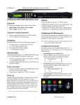
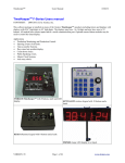
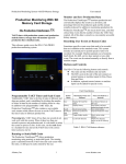
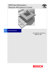
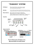
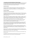
The Queuer™ Operating Instructions The Tallye™ The Queuer™ Request-to-Speak System The Tallye™ Electronic Voting System The system can be configured in several ways. • Request-to-speak system. • Electronic voting system. • Combination request-to-speak and electronic voting system. The combination system shares the same request-to-speak/voting control stations. The block diagram below shows the generic sections of each system and the economical design that allows for expansion as your needs grow. Alzatex, Inc. 1 www.alzatex.com The Queuer™ Operating Instructions The Tallye™ The Queuer™ Request-to-Speak System The Request-to-Speak System consists of: • Master Control Module. • Chairperson's Console. • Microphone Mute Module. • Queuing/Voting Station Control Module. • One Queuing/Voting Station for each member • One or more LCD or VFD (vacuum florescent) displays to indicate the order in which people have requested to speak. • Integrated timer and time of day clock. This unit has outputs to send data to remote displays, video character generator and/or a printing device. Microphone Mute Module The microphone mute module is part of the rack unit. The outputs from this unit connect to the ground closure mute inputs on the mixer. Chairperson’s Console The Chairperson’s Console is available in several standard formats or may be custom designed to suit your application. The Chairperson’s Console typically has the following: Master Control Module • TimeKeeper integrated count up, count down timer with time of day clock. • Talk buttons and request to speak indicators. • LCD or vacuum florescent display to indicate the order in which people have requested to speak. • A “Mute ALL” button to mute all but the chairperson’s microphone. The QUE-521A Request-to-Speak System Master Control module has three sections. • Podium MUTE button to mute or enable the podium microphone. • Master Control. • • Countdown timer display. Chairperson’s voting station. (for systems that combine both queuing and voting) Pictured below is the Request-to-Speak System Master Control module with the microphone mute relay display. QUE-512A Master Control Module Chairperson's Console • Microphone mute module. Enlargement of QUE-512A Display The Chairperson’s Console has large multi-color buttons, an LCD display to indicate the order in which people have requested to speak and an integrated count down timer with time of day clock. The TALK indicators turn yellow for request to speak and green for speaking. The LCD or VFD display shows the list of persons requesting to speak and who is speaking. The QUE-521A Request-to-Speak System Master Control module stores the names and processes the requests to speak. This unit also places the person into the queue or removes persons from the queue. Alzatex, Inc. 2 www.alzatex.com The Queuer™ Operating Instructions The Tallye™ Queuing/Voting Station Control Module All of the queuing/voting stations connect to the QUE-115A queuing/voting station control module. This unit is usually located near the dais. Alternate Chairperson’s Console with Voting Results Display An alternate Chairperson’s Console is available for use with a combined Request-to-Speak and Voting system that has small buttons and multicolor LED indicators, vacuum florescent display to indicate the order in which people have requested to speak and an integrated count down timer with time of day clock. This unit also includes an integrated Chairperson’s Voting Station and a mini Voting Results Display. The TimeKeeper COUNT DOWN TIMER QUE-115A Station Control Module Each of the QUE-115A units can handle up to 15 queuing/voting stations. Multiple QUE-115A modules may be connected together for larger systems. The COUNT DOWN TIMER Queuing/Voting Stations The integrated TimeKeeper COUNT DOWN TIMER keeps track of the number of minutes that a person is speaking. There are three standard types of queuing/voting stations; One, Two, or Three button. In addition, queuing/voting stations are available in either flush mount or portable versions. The MUTE ALL Button The ONE BUTTON Queuing Station The MUTE ALL button The MUTE ALL button will mute all of the microphones except the chairperson’s. Flush-mount ONE BUTTON Queuing Station……. TALK Button Configuration The ONE BUTTON queuing station has a single lighted push button and a RJ-45 network connector. The system may be configured such that only the chairperson can turn on each microphone or such that either the chairperson or the speaker can turn on each microphone. Alzatex, Inc. Note that the ONE BUTTON queuing station is not usable as a voting station. 3 www.alzatex.com The Queuer™ Operating Instructions The Tallye™ Request to Speak Button When the button is pressed, the button turns yellow indicating that this person’s Request to Speak has been placed in the Queue. Request-to-Speak Queue Display When the chairperson presses the respective button on the Chairperson’s Console, the queuing/voting station button turns green indicating that the microphone is turned on and that it is OK to speak. The person's name is displayed on the Queue Display at the end of the Request-to-Speak list. Since the displays have only 4 lines, only the four highest priority names are displayed. TALK Button (Speaking) Network Connector Pressing the TALK button indicates that the person at the respective queuing/voting station is going to talk. The TALK indicator lights green. If a microphone is connected, it is enabled. This connector provides easy access to the computer network. It is not related in any way to the Request-to-Speak System. The person's name is displayed on the Queue Display at the top of the list. The word "TALK" is displayed next to the person's name. If the QUEUE indicator is lit, it is extinguished. The TWO BUTTON Queuing/Voting Station TWO BUTTON queuing/voting stations have two lighted push buttons. The TWO BUTTON flush-mount stations also include a place to install a microphone. Flush-mount TWO BUTTON Portable TWO BUTTON Queuing/Voting Station …with Microphone mount Depending on the configuration of the queuing station, the microphone may or may not be activated when the TALK button is pressed. When the person is finished speaking, either the chairperson or the speaker can press the TALK button again to turn off the microphone and the speaker’s name will be removed from the queue list. Queuing/Voting Station • The QUEUE (request to speak) button. • The TALK (Speaking) button. • Pressing both buttons simultaneously clears both the QUEUE and TALK indicators. The THREE BUTTON Queuing/Voting Station THREE BUTTON queuing/voting stations have three buttons and two LED indicators. QUEUE Button (Request-to-Speak) Pressing the QUEUE button indicates that the person at this queuing station desires to speak. The QUEUE indicator lights yellow. Flush-mount THREE BUTTON Station Alzatex, Inc. 4 www.alzatex.com The Queuer™ Operating Instructions • The QUEUE (request-to-speak) button. • The TALK (Speaking) button. • The CLEAR button clears both the QUEUE and TALK indicators. The Tallye™ Programming lists of names You may enter up to 8 lists of names for up to 8 types of meetings with different persons. The lists are labeled A through H. Connect a PS2 style keyboard to the Request-toSpeak System Master Control Module. QUEUE Button (Request-to-Speak) Pressing the QUEUE button indicates that the person at this queuing/voting station desires to speak. The QUEUE indicator lights yellow. • Press the F1 key to enter the programming mode. • The person's name is displayed on the Queue Display at the end of the Rrequest-to-Speak list. Since the displays have only 4 lines, only the four highest priority names are displayed. Press the F2 or F3 keys to select the virtual station number. The virtual station number is the station number that you see in the display. • Press the F4 key to save the virtual station number into memory. TALK Button (Speaking) • The PAGE UP and PAGE DOWN keys select the list of names to be edited. Pressing the TALK button indicates that the person at the respective queuing/voting station is going to talk. The TALK indicator lights green. If a microphone is connected, it is enabled. • The UP, DOWN, LEFT and RIGHT keys select the name within the list to be edited. • After typing in the desired changes, press the ENTER key to save the new name. The person's name is displayed on the Queue Display at the top of the list. The word "TALK" is displayed next to the person's name. If the QUEUE indicator is lit, it is extinguished. • When editing is complete, press the ESC key to exit the programming mode. • You may now unplug the keyboard. NOTE: The keyboard may be plugged in or removed at any time even if the power is on Depending on the configuration of the queuing station, the microphone may or may not be activated when the TALK button is pressed. Selecting the list of names When the person is finished speaking, either the chairperson or the speaker can press the TALK button again to turn off the microphone and the speaker’s name will be removed from the queue list Before each meeting, you must select the list of names that you plan to use. • Be sure that none of the queuing stations are selected. The current list of names will be displayed. Setting Up the Master Control Module • Press the UP and DOWN buttons on the QUE-521A to select the letter (A – H) corresponding to the desired list of names. Queuing/Voting Station Configuration It is often desirable to have the numbers that are assigned be the same as the numbers assigned to the queuing stations. The position numbers associated with the names can be changed to match the microphone number assignments. Master Control Module Alzatex, Inc. 5 www.alzatex.com The Queuer™ Operating Instructions Connect a PS2 style keyboard to the Request-toSpeak System Master Control Module. The system will automatically enter the programming mode. • • Using the UP and DOWN keys select the name that you wish to edit. • Type in two numeric digits 00 to 99 • Press the ENTER key to save. • Repeat these steps for each of the queuing stations. NOTE: The number assignments affect all of the lists of names at the same time. It doesn’t matter which list of names you edit. All the lists will be changed. Press the F1 key. The physical queuing station number will be in line two of the display. The number you are changing will be in line three. Alzatex, Inc. The Tallye™ 6 www.alzatex.com The Queuer™ Operating Instructions The Tallye™ The Tallye™ Voting System The voting system consists of: • Voting System Controller. • Queuing/Voting Station Control Module. • One Queuing/Voting station for each member • Voting Results Display (at least one). The center of the unit is reserved for labeling the name of the voting member associated with each voting station. Mini-Vote Results Display is located on the right side. A RED LED indicating a NO vote. A GREEN LED indicating a YES vote. Voting System Controller A BLUE LED indicating abstaining. The Voting System Controller is used to enable and disable the voting process. This unit also enables the vote results to be displayed. The Voting System Controller has the following controls and indicators. The four sections at the bottom of the Voting System Controller (left to right) are: VOTE ENABLE button and indicator. PRINT button and indicator if a printer is installed. VOTE PREVIEW button and indicator to turn on the mini-vote results display. VOTE DISPLAY button and indicator to control the large wall display and other mini-vote results displays. Voting Stations Voting System Controller/Clerk’s Station There is a voting station for each person that is allowed to vote. Each queuing/voting station has several buttons. The integrated TimeKeeper count up / count down timer used to time speakers is at the top of the unit. This timer is connected to and controls the Chairperson’s timer, RYG display or large wall display. The middle section (left to right): The NO button. • The YES button. • The ABSTAIN button. NOTE: On two button stations press both the YES and NO buttons simultaneously to record an ABSTAIN vote. ROLL CALL buttons and LED indicators for each of the voting stations to mark the persons present or absent. Some organizations prefer to permit Yes or No votes only and not allow Abstain as a choice. These organizations should use the TWO BUTTON queuing/voting station. VOTED LED indicators for each of the voting members to indicate that during the voting process, each person has recorded his/her vote. Alzatex, Inc. • 7 www.alzatex.com The Queuer™ Operating Instructions Vote Results Displays The Tallye™ stop blinking and will display the selected vote. The corresponding VOTED LED indicator on the Voting Station Controller will come on steady. The results of a vote can be displayed on one or more display devices simultaneously. A typical system includes the large wall display shown below and may or may not include desktop minivote displays. The vote may be changed at any time during the voting process until voting has been locked at the Voting System Controller. Once everyone has voted, the VOTED LEDs for all of the members present on the Voting System Controller will be on. 4 -To lock the vote in place, press the VOTE ENABLE button again to disable any further change. Displaying the vote results Large Wall Vote Display The VOTE PREVIEW button on the Voting System Controller will permit the clerk to view the vote results on the Voting System Controller only. Desktop miniVote Display Alternately, the vote results may be projected through an LCD projector instead of using the large wall display. The VOTE DISPLAY button on the Voting System Controller will permit the members and audience to view the vote results. It can be pressed at any time during or after the vote to display the current status. The Voting Process 1 - Press the respective ROLL CALL button for each of the members that will be voting. Open Vote 2 - To initiate the voting process, press the VOTE ENABLE button on the Voting System Controller. Any previous vote results are cleared. Press the VOTE DISPLAY button after pressing the VOTE ENABLE button. As voters make their selection, the results will be immediately displayed. On the Voting Station Controller, the VOTE ENABLE LED will turn on. On each voting station that has been enabled by the ROLL CALL button, both the YES and NO indicators will begin blinking. Secret Vote Once everyone has voted, press the VOTE ENABLE button to lock the vote into the system. 3 -Each of the voting members should select YES, NO or ABSTAIN on the respective voting station. Press the VOTE DISPLAY button to display the vote results on the large wall display. Once the vote button has been pressed, the indicators at the respective voting station will Once a new vote is initiated by pressing the VOTE ENABLE button, the previous vote results are cleared. Alzatex, Inc. 8 www.alzatex.com The Queuer™ Operating Instructions The Tallye™ The TimeKeeper™ Count up/down timer with Clock The Timekeeper™ system is integrated into the Queuer™ Request-to-Speak System and the Tallye™ voting system. In addition any of the standard Timekeepers™ and displays may be used with the system. • Press Reset to select timer mode. • Turn knob to set desired time. The Select button selects between setting minutes and seconds. • Press the Start/Stop button to start the timer. The TimeKeeper is available as a count-down only timer or a user-selectable count-up / countdown timer with an added MODE button. The MODE button selects between count-up and count-down modes. You may change between elapsed time and time remaining modes while the timer is running. In count down mode, the timer stops when it reaches zero. In count up mode, the timer keeps running when the preset time is reached. This is the count-down only version Countdown Timer Wall Display The large LED Wall Display permits the audience to see the count down time. Press and hold the Mode button to turn the beep on or off. Press and hold the Select button to set the Wrap-It-Up time. Press the Select button again to set the Green warning time. Clock Mode • Press Clock button to select clock mode. • The Select button selects displaying 12 hour time, military time or minutes and seconds. In 12 hour mode, the PM LED will be on for PM and off for AM. Timer Wall Display Red-Yellow-Green Display The Red-Yellow-Green Display may be either surface mounted or flush mounted. Setting the Clock. Press and hold the Clock button to enter set time mode Red-Yellow-Green (RYG) Display Turn the Knob to set the hours. • Press the Clock button again. • Turn the Knob to set the minutes. • Press the Clock button again to return to normal display. Red-Yellow-Green Display Operating The TimeKeeper Timer Mode Alzatex, Inc. • 9 www.alzatex.com The Queuer™ Operating Instructions • In the count down mode, the Green lamp comes on when the timer is started and begins to blink at the green warning time. In the count up mode, the Green lamp comes on at the green warning time. • When the Yellow warning time is reached, the Green lamp goes off and the Yellow lamp comes on. • When the timer reaches zero, the Red lamp comes on and the Yellow lamp goes off. In the count down mode, the timer stops when the Red lamp turns on. In the count up mode, the timer keeps running after the lamp turns Red. • Press the reset button on the TimeKeeper™ to turn off the Red lamp. Red warning Yellow warning Green warning Total time 0:00 1:00 2:00 5:00-99:59 0:00 0:30 1:00 2:00 - 4:59 0:00 0:15 0:30 1:00 - 1:59 0:00 0:10 0:20 0:30 - 0:59 0:00 0:01 0:02 0:00 - 0:29 The Tallye™ Multiple TimeKeepers™ When a system has multiple Timekeepers™ installed, one of the units becomes the master and the other units become slaves. • After powering up the system, press any button on the unit you wish to become the master. All of the other units will automatically become slaves. To make a different unit master, remove the power and press any button on the new unit that you wish to become master Alzatex, Inc. 10 www.alzatex.com