1
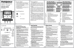
Axiom Technologies LLC
15711 W. Hardy Road, Suite 1
Houston, Texas 77060
Telephone: 281 931 0907
Fax: 281 231 6562
www.axiomsafety.com
XH5D-HE
USER’S MANUAL
SELF-CONTAINED, DUAL PUMP
WELLHEAD CONTROL PANEL
FOR HARSH ENVIRONMENTS
Axiom Technologies LLC
XH5D-HE User’s Manual
15711 W. Hardy Rd., Suite 1, Houston, Texas 77060
Phone 281 931 0907
GENERAL
The XH5D-HE self-contained system is a device designed and built for protecting oil and gas
production wells. It includes a switch-gage to detect high and low pressures as well as hydraulic
interface for fire detection and manual ESD.
The XH5D-HE is self-sufficient and doesn’t need external sources of energy or supply pressure
for keeping a wellhead open and protected. It uses hydraulic fluid for driving the surface and
sub-surface valves and it has two separate hand pumps and dump valves for independent control
of the SSV and SCSSSV
The detection of High and Low pressures is done by a switch-gage with adjustable contacts for
detecting when the monitored pressure is out of acceptable limits. The switch-gage connects to
an electronic module that indicates High and Low pressure conditions as well as initiates the
shutdown when a pressure alarm is detected. The electronic circuits are fed by a battery module
capable of keeping the system operating for five (5) years.
The XH5D-HE is built to operate exposed to the elements as all hydraulic components are
enclosed in a stainless steel box while the electronic circuits and battery module are enclosed in a
explosion proof box inside the stainless steel box. The front of the panel includes the gages and
controls as shown in Fig.1 while the inside components are shown in Fig. 2.
Flow Pressure w/
High and Low
Pressure Alarm
“Reset” – “Test”
Switch
LED Indicators:
-High Press. Alarm
-Low Press. Alarm
-Low Battery Alarm
-Auxiliary Alarm
-Telemetry Stdn
-“Heart Beat”
(System OK)
“Pilot” Pressure
SSV Actuator
Pressure.
SCSSSV Pressure
Hydraulic Pump
SCSSSV
“SSV – Pilot”
Pumping Selector
Valve
Hydraulic Pump
“SSV – Pilot”
“In Service – ESD”
Selector Valve
(Manual Shutdown)
Fig. 1 XH5D-HE Front Panel.
XH5D-ME-R2.doc
5/11/2013
Page 2 of 10
Axiom Technologies LLC
XH5D-HE User’s Manual
15711 W. Hardy Rd., Suite 1, Houston, Texas 77060
Electronic Enclosure
Solenoid Valve
Phone 281 931 0907
Piston Accumulator
(Diaphragm Accum.
Directly behind)
Flow Control Valve
(SCSSSV Closing
Delay Adjustment)
SSV Dump Valve
(SCSSSV Dump
Valve directly
behind)
Hydraulic Reservoir
Pilot Pressure Relief
Valve
Dual Hydraulic Hand
Pump
Hydraulic Filter
Hydraulic Level
Indicator
Fig. 2 – XH5D-HE Enclosure’s Interior
INSTALLATION – PRELIMINARY STEPS AND TESTS
The XH5D-HE is typically sent with the battery module mounted backwards or in a separate
package for preventing the system from operating while in transit. Also, as needed to meet
shipping regulations, the device is typically shipped without hydraulic fluid in the reservoir and
without Nitrogen pre-charge in the SSV hydraulic accumulator (the larger of the two
accumulators. (The pilot pressure accumulator uses only 50 psi of Nitrogen pre-charge and
considered safe for air transport.)
Before installing the system is to be inspected to confirm that there is no external damage or
indication of rough handling during shipment.
In case of overseas shipments it is recommended that the XH5D-HE is tested in a work shop near
the final destination to facilitate the commissioning and allow the operators to become familiar
with the unit.
NOTE
It is recommended that the operator becomes familiar with the Hydraulic Schematic
(Appendix “B”) and have a copy handy during the tests described below to better
understand the system’s behavior.
XH5D-ME-R2.doc
5/11/2013
Page 3 of 10
Axiom Technologies LLC
XH5D-HE User’s Manual
15711 W. Hardy Rd., Suite 1, Houston, Texas 77060
Phone 281 931 0907
To commission the system follow with the steps listed below:
i. Pre-charge 16 CU IN piston accumulator with about 1,000 PSI of Nitrogen
ii. Confirm pre-charge of the 6 CU IN diaphragm accumulator with 50 PSI of
Nitrogen.
iii. Add hydraulic fluid to the reservoir, approximately one gallon. Filling is to be
done with care not to exceed about 2/3rd of capacity. (In factory the units are
tested with “Megaflow” ™ AW Hydraulic Oil 32, however, any quality hydraulic
fluid with a AW32 will operate well.)
iv.
Open Explosion Proof Box mounted inside the stainless steel box and install
battery module as indicated in Appendix “A”. By doing this the electronic circuit
becomes energized and the green LED blinks every second (Heartbeat) to indicate
the electronic circuit is operating without problem.
v.
Before pressurizing panel it is recommended that hydraulic fluid is circulated
throughout the system to flush any particle and contaminants that could be present
within the hydraulic lines. With this purpose proceed as follows:
vi.
vii.
viii.
ix.
x.
xi.
xii.
a) Set valve “In Service – ESD” to “ESD”.
b) Set valve “SSV - Pilot” to “Pilot”
c) Pump “Pilot/ SSV”(right side pump) in a fast mode for approximately one
minute while observing the “Pilot” pressure gage (right side of the panel).
This gauge should display “0” PSI but the needle oscillates with each
pump strike.
d) Set valve “SSV – Pilot” to “SSV”
e) Again, pump “Pilot/ SSV” (right side pump) in a fast mode for
approximately one minute while observing the “SSV” pressure gauge
(center of the panel). This gauge should stay in “0” PSI
f) Pump “SCSSSV”(left side pump) in a fast mode for approximately one
minute while observing the “SCSSSV” pressure gage (left side of the
panel). This gauge should stay in “0” PSI.
Confirm that the plugs on the bulkhead connectors are tight before proceeding
with the following steps.
Set valve “In Service – ESD” to “In Service”.
Set valve “SSV - Pilot” to “Pilot”
Press “Reset” on switch “Test – Reset”.
Pump “Pilot/ SSV” (right side pump) while observing the “Pilot” pressure gauge.
Pump until reaching between 80 and 90 PSI. Inspect hydraulic lines to confirm
that there is no leakage.
Pump “SCSSSV” pump (left side pump) while observing the “SCSSSV” pressure
gauge. Pump until reaching about 10,000 PSI. Inspect hydraulic lines to confirm
that there is no leakage. As this test is being done with the SCSSSV output
blocked the pressure will rise quickly and the pressure will decrease in about 20 to
30% in a few seconds after the pumping stops. This is normal; however, after the
initial pressure decrease the pressure should remain stable except for the effects of
temperature changes.
Set valve “SSV - Pilot” into “SSV”
XH5D-ME-R2.doc
5/11/2013
Page 4 of 10
Axiom Technologies LLC
XH5D-HE User’s Manual
15711 W. Hardy Rd., Suite 1, Houston, Texas 77060
xiii.
xiv.
Phone 281 931 0907
Pump “SSV - Pilot” pump (right side pump) while observing the “SSV” pressure
gauge. Pump until reaching 3,000 PSI. Inspect hydraulic lines to confirm that
there is no leakage. It is normal for the pressure to fall about 15% after finishing
the pumping.
Set valve “In Service – ESD” to “ESD” to return all pressures to cero before
moving the XH5D-HE to the field for installation.
FIELD INSTALLATION
Typically the XH5D-HE is mounted on one or two poles made of 3” pipe. Using two poles is
preferred as it would insure safe mounting even if one of the pipe brackets used for fastening the
panel to the poles would fail. The two poles should have a separation of 10” to 15” (25cm to
38cm) center to center. The pipe brackets connect to the unistrut channel mounted on the left
side of the panel
Fig. 3 – XH3 Mounting
With the panel firmly mounted, proceed to connect the field devices as shown on Fig. 4.
XH5D-ME-R2.doc
5/11/2013
Page 5 of 10
Axiom Technologies LLC
XH5D-HE User’s Manual
15711 W. Hardy Rd., Suite 1, Houston, Texas 77060
Phone 281 931 0907
-1Flow-line Sensing
Pressure
-2Hydraulic pressure
to SSV
-3Hydraulic pressure
to SCSSSV
-4Hydraulic pressure
to Manual ESD/Fire
Sensor
-5Hydraulic return
from Manual
ESD/Fire Sensor.
Fig. 4 – Rear view, hydraulic lines connections.
The connection to the ESD station (Connection No. 4) can be also connected to a fire plug
(Included). If the fire plug used does not have a return line, some means are to be used to
prevent hydraulic fluid from reaching the ground. A small amount of hydraulic fluid
(approximately 3 CU IN or 50 CC) will be released in the event of a fire.
XH5D-ME-R2.doc
5/11/2013
Page 6 of 10
Axiom Technologies LLC
XH5D-HE User’s Manual
15711 W. Hardy Rd., Suite 1, Houston, Texas 77060
Phone 281 931 0907
OPERATION AND ADJUSTMENTS
The operation of the installed panel is as follows:
Starting Production:
1- Set valve “In Service – ESD” to “In Service”
2- Set valve “SSV - Pilot” to “Pilot”.
3- Press “Reset” on switch “Test – Reset”.
4- Pump “Pilot/ SSV” (right side pump) while observing the “Pilot” pressure gauge until
reaching 80 to 90 PSI.
5- Pump “SCSSSV” pump (left side pump) while observing the “SCSSSV” pressure
gauge. Pump until reaching the pressure necessary to open SCSSSV. Do not exceed
12,000 PSI.
6- Set valve “SSV - Pilot” into “SSV”.
7- Pump “SSV - Pilot” pump (right side pump) while observing the “SSV” pressure
gauge. Pump until SSV is fully opened plus about 500psi reaching. Do not exceed
actuator’s pressure rating. It is normal for the pressure to fall about 15% after finishing
the pumping.
8- Check all hydraulic connections (internal and external to the panel) to confirm that
there is no leakage.
9- Adjust High and Low Alarm set point on switch-gage.
Closing SSV:
10- Move High or Low Alarm Set-Point until it touches the gage’s needle. The system
responds closing the SSV. The corresponding LED (High or Low Pressure Alarm)
blinks and the green LED stops blinking. There is no change on pilot pressure but the
SSV pressure goes to cero.
Re-opening the SSV:
11- Press “Reset”. The Alarm LED stops blinking while the green LED (Heartbeat) blinks
every second. Also, as the solenoid trips, the pilot pressure goes momentarily to cero
and slowly returns to approximately 80 PSI.
12- Pump “Pilot/ SSV” (right side pump) while observing the “Pilot” pressure gauge until
reaching 80 to 90 psi.
13- Set valve “SSV - Pilot” into “SSV”.
14- Pump “SSV - Pilot” pump (right side pump) while observing the “SSV” pressure
gauge. Pump until reaching 3,000 PSI. It is normal for the pressure to fall about 10%
after finishing the pumping. Do not exceed 3,000 PSI.
Initiating ESD (Clothing of the SSV and then SCSSSV):
15- Set valve “In Service – ESD” to “ESD”.
Shutdown Delay adjustment for SCSSSV:
16- The SCSSSV closes only in case of manual ESD and/or by the activation of the fusible
plug.
17- When an ESD is initiated, the “Pilot Pressure” and “SSV Pressure” shown on the front
of the panel go to zero psi in the first one or two seconds. Then after some time delay,
the SCSSSV pressure slowly goes down to zero.
18- The time lapsing between the activation of the ESD can be adjusted by adjusting the
“Flow Control Valve” (shown on Fig.2, page 3 of this manual).
XH5D-ME-R2.doc
5/11/2013
Page 7 of 10
Axiom Technologies LLC
XH5D-HE User’s Manual
15711 W. Hardy Rd., Suite 1, Houston, Texas 77060
Phone 281 931 0907
19- Turn knob of “Flow Control Valve” a small fraction of a turn in the direction of the
clock pointers to increase time delay and in the opposite direction to reduce it.
20- For initial setting close the “Flow Control Valve“ by turning knob clockwise all the
way and then turning it back one half of a turn
Re-opening the well after ESD:
21- Repeat steps 1 through 9 of this list.
Adjusting High and Low Pressure Alarms:
22- Turn red knob to adjust High pressure Alarm to the desired High Pressure Alarm.
Repeat the same with the black knob to set the Low Pressure Alarm.
HYDRAULIC CIRCUITS
The hydraulic circuits are shown on appendix “B”.
ELECTRONIC SYSTEM
By replacing most of the hydraulic logic with electronic circuits, the most failure prone
components are removed and the hydraulic circuit greatly simplified to a few reliable
components. In this way, by having self diagnostic in the electronics and a simplified hydraulic
system, the XH5D-HE offers a reliability level not seen on any of the typical self-contained
wellhead control panel. Furthermore, if a failure would occur, the diagnostic and correction of
the problem is much simpler because of the simplicity of the hydraulics.
`
Telemetry Shutdown
Alarm
Auxiliary Alarm a
See Appendix C for
Auxiliary or
Telemetry Shutdown
Spare EOZ
Fig. 4 – External Alarm Termination Box
XH5D-ME-R2.doc
5/11/2013
Page 8 of 10
Axiom Technologies LLC
XH5D-HE User’s Manual
15711 W. Hardy Rd., Suite 1, Houston, Texas 77060
Phone 281 931 0907
When operating under normal conditions (no alarms) the electronic system flashes the green
LED every second (heartbeat) to indicate that the electronic system is operating without
problems.
If any alarm is detected the green LED stops flashing and the solenoid valve is tripped to
initiate shutdown of the SSV only. The red LED corresponding to the detected alarm starts
flashing and it is latched in such way that even if the alarm condition would go away or a new
alarm would be detected; the first detected alarm only will flash, holding the information for the
operator to see the actual cause of the shutdown. For example, if a High Pressure Alarm would
occur, the corresponding High Pressure Alarm LED will flash and keep on flashing even if the
high pressure alarm would go away and now the needle is touching the Low Pressure contact.
The first detected alarm will keep displaying until the operator presses “Reset”.
A total shutdown or “ESD” (closing of the SSV and SCSSSV) would be executed only in the
case of Fire Alarm (fusible plug) and/or Manual Shutdown.
Once the operator presses “Reset” while the alarm still present, the system resets the solenoid
valve to allow the re-opening of the well and alternatively flashes the green LED and
corresponding alarm red LED, if the alarm still present. The system tolerates the existing alarm
for 30 minutes before re-initiating the shutdown and prevents the system from being left in
production while operating in an abnormal condition. Once the pressure alarm clears, only the
green LED remain flashing.
The “Test” function allows the operator to see the last alarm and also confirm that all the
indicator LEDs are working properly. This is, when pressing “Test”, the system respond by
flashing the last detected alarm for about two seconds and then flashes the red LEDs in sequence.
The battery module provides two separate voltages, 3.6 VDC to feed the microcontroller circuits
and 14.4 VDC to operate the solenoid valve. Both voltages are periodically monitored to
confirm the system has the proper battery supply to operate reliably.
If the system detects a low voltage, the green LED and the “Low Battery” red LED alternates
flashing but the system remains in operation. However, if a voltage falls too far down for
insuring reliable operation, then a shutdown is executed and only the “Low Battery” red LED
flashes.
Given the low power consumption of the system it is expected that the operator will be able to
detect the warning signs of low battery and should be able to replace the battery module before it
gets to the point where the system causes shutdown because low battery.
The battery module is to be replaced as soon as the system shows signs of low voltage to insure
the system continues operating reliably. The battery module has an expected life of five years
XH5D-ME-R2.doc
5/11/2013
Page 9 of 10
Axiom Technologies LLC
XH5D-HE User’s Manual
15711 W. Hardy Rd., Suite 1, Houston, Texas 77060
Phone 281 931 0907
WARNING!
Do not attempt to recharge the batteries on the battery
module as this may cause an instable condition that may
result in a violent explosion.
Return the spent battery modules to Axiom Technologies or
to any lithium battery recycling facility.
See the instructions shown on Appendix “A” for replacing the battery module.
XH5D-ME-R2.doc
5/11/2013
Page 10 of 10