1
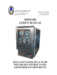
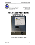
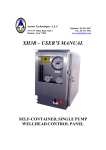
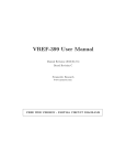
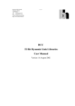
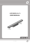
Axiom Technologies L.L.C
15711 W. Hardy Road, Suite 1
Houston, Texas 77060
Telephone: 281 931 0907
Fax: 281 231 6562
www.axiomsafety.com
XH5
USER’S MANUAL
SELF-CONTAINED, SINGLE PUMP
WELLHEAD CONTROL PANEL
Axiom Technologies
15711 West Hardy Rd,, Suite 1
XH5 User’
Phone 281 931 0907
GENERAL
The XH5 self-contained system is a device designed and built for protecting oil and gas
production wells. It includes a switch-gage to detect high and low pressures, connects up two
electronic external alarm signals as well as a hydraulic interface for fire detection and manual
ESD.
The XH5 is self-sufficient and doesn’t need external sources of energy or supply pressure for
keeping a wellhead open and protected. It uses hydraulic fluid for driving the SSV and it has a
hand pump and dump valve for controlling production.
The detection of High and Low pressures is done by a switch-gage with adjustable contacts for
detecting when the monitored pressure is out of acceptable limits. Also, the XH5 can be
connected to remote shutdown signals such as “Auxiliary/Remote Shutdown” (i.e. a shutdown
signal from an external process control panel) and “Telemetry Shutdown” that can be connected
to an RTU output signal.
Both external signals (Aux./ Remote and Telemetry) are monitored for wiring loop integrity in
such a way that wiring failure will be detected and indicated.
The electronic circuits are fed by a battery module capable of keeping the system operating for
five (5) years.
“Reset” – “Test” Switch
LEDs
- High Pressure Alarm
- Low Pressure Alarm
- Aux/Remote Alarm
- Telemetry Alarm
- Low Battery Alarm
- Pulse Indication (Green)
“Pilot” Pressure
Hydraulic Pump
Flow Pressure w/
High and Low
Pressure Alarm
SSV Actuator
Pressure
“SSV – Pilot”
Selector Valve
“In Service – ESD”
Selector Valve
Fig. 1 XH5 Controls Interface
XH5-ME-R1.doc
Page 2 of 9
Axiom Technologies
XH5 User’
15711 West Hardy Rd,, Suite 1
Phone 281 931 0907
The XH5 is built to operate exposed to the elements as all hydraulic components are enclosed in
a stainless steel box while the electronic circuits and battery module are enclosed in an explosion
proof box inside the stainless steel box. The inside components are shown in Fig. 2.
Operator Interface Module
Diaphragm Accumulator
(Pilot Pressure)
Switch
Gage
Electronic Enclosure
Solenoid Valve
SSV Dump Valve
Pilot Pressure Relief
Valve
Hydraulic Level Indicator
Hydraulic Hand Pump
Diaphragm Accumulator
(High Pressure)
Fig. 2 – XH5 Enclosure’s Interior
INSTALLATION – PRELIMINARY STEPS AND TESTS
The XH5 is sent with the battery module not mounted to prevent the system from operating
while in transit. Also, as needed to meet shipping regulations, the device is typically shipped
without hydraulic fluid in the reservoir and without Nitrogen pre-charge in the accumulators.
Before installing the system, it is to be inspected to confirm that there is no external damage or
indication of rough handling during shipment.
In case of overseas shipments it is recommended that the XH5 is tested in a work shop near the
final destination to facilitate the commissioning and allow the operators to become familiar with
the unit.
NOTE
XH5-ME-R1.doc
Page 3 of 9
Axiom Technologies
15711 West Hardy Rd,, Suite 1
XH5 User’
Phone 281 931 0907
It is recommended that the operator becomes familiar with the Hydraulic Schematic
(Appendix “B”) and have a copy handy during the tests described below to better
understand the system’s behavior.
To commission the system follow with the steps listed below:
i. Pre-charge 20 CU IN diaphragm accumulator with 500 PSI of Nitrogen
ii.
Pre-charge 5 CU IN diaphragm accumulator with 40 PSI of Nitrogen.
iii. Add hydraulic fluid to the reservoir, approximately one gallon if reservoir is
empty. Filling is to be done with care not to exceed the “High” level mark in the
liquid gauge.
iv.
Open Explosion Proof Box mounted inside the stainless steel box, and install
battery module as indicated in Appendix “A”. By doing this the electronic circuit
becomes energized and the green LED blinks every second (Heartbeat) to indicate
the electronic circuit is operating without problem.
v.
Before applying pressure it is recommended that hydraulic fluid is circulated
throughout the system to flush any particle and contaminants that could be present
within the hydraulic lines. With this purpose proceed as follows:
vi.
vii.
viii.
ix.
x.
xi.
xii.
xiii.
a) Set valve “In Service – ESD” to “ESD”.
b) Set valve “SSV - Pilot” to “Pilot”
c) Pump “Pilot/ SSV” in a fast mode for approximately one minute while
observing the “Pilot” pressure gage. This gauge should display “0” PSI
but the needle oscillates with each pump strike.
d) Set valve “SSV – Pilot” to “SSV”
e) Again, pump “Pilot/ SSV”in a fast mode for approximately one minute
while observing the “SSV SSV” pressure gauge. This gauge should stay
in “0” PSI
Confirm that the plugs on the bulkhead connectors are tight before proceeding
with the following steps.
Set valve “In Service – ESD” to “In Service”.
Set valve “SSV - Pilot” to “Pilot”
Press “Reset” on switch “Test – Reset”.
Pump “Pilot/ SSV” while observing the “Pilot” pressure gauge. Pump until
reaching 80 PSI. Inspect hydraulic lines to confirm that there is no leakage.
Set valve “SSV - Pilot” into “SSV”
Pump “SSV - Pilot” pump while observing the “SSV” pressure gauge. Pump
until reaching 1,500 PSI. Inspect hydraulic lines to confirm that there is no
leakage. It is normal for the pressure to fall about 10% after finishing the
pumping.
Set valve “In Service – ESD” to “ESD” to return all pressures to cero before
moving the XH5 to the field for installation.
FIELD INSTALLATION
Typically the XH5 is mounted on one or two poles made of 3” pipe. Using two poles is
preferred as it would insure safe mounting even if one of the pipe brackets used for fastening the
panel to the poles would fail. The two poles should have a separation of 10” to 15” (25cm to
XH5-ME-R1.doc
Page 4 of 9
Axiom Technologies
15711 West Hardy Rd,, Suite 1
XH5 User’
Phone 281 931 0907
38cm) center to center. The pipe brackets connect to the strut channel mounted on the left side
of the panel
With the panel firmly mounted, proceed to connect the field devices to the rear of the panel.
The connection to the ESD station can be also connected to a fire plug. If the fire plug used does
not have a return line, some means are to be used to prevent hydraulic fluid from reaching the
ground. A small amount of hydraulic fluid (approximately 3 CU IN or 50 CC) will be released
in the event of the fire plug responding to a fire.
OPERATION AND ADJUSTMENTS
The operation of the installed panel is as follows:
Starting Production:
1- Set valve “In Service – ESD” to “In Service”
2- Set valve “SSV - Pilot” to “Pilot”.
3- Press “Reset” on switch “Test – Reset”.
4- Pump “Pilot/ SSV” while observing the “Pilot” pressure gauge until reaching 60 PSI.
5- Set valve “SSV - Pilot” into “SSV”.
6- Pump “SSV - Pilot” pump while observing the “SSV” pressure gauge. Pump until
reaching 1,500 PSI. It is normal for the pressure to fall about 15% after finishing the
pumping. Do not exceed maximum actuator’s pressure.
7- Check all hydraulic connections (internal and external to the panel) to confirm that
there is no leakage.
8- Adjust High and Low Alarm set point on switch-gage.
Closing SSV:
9- Turn “In Service – ESD” valve to “ESD”. The system responds closing the SSV.
Re-opening the SSV:
10- If any of the red LEDs is flashing Press “Reset”. The Alarm LED stops blinking while
the green LED (Heartbeat) blinks every two seconds.
11- If “In Service – ESD” valve is on “ESD” turn it to “In Service”
12- Set valve “SSV - Pilot” to “Pilot”.
13- Pump while observing the “Pilot” pressure gauge until reaching 80 PSI.
14- Set valve “SSV - Pilot” into “SSV”.
15- Pump “SSV - Pilot” pump while observing the “SSV” pressure gauge. Pump until
reaching 1,500 PSI. It is normal for the pressure to fall about 10% after finishing the
pumping. Do not exceed 2,000 PSI.
Adjusting High and Low Pressure Alarms:
16- Turn red knob to adjust High pressure Alarm to the desired High Pressure Alarm.
Repeat the same with the black knob to set the Low Pressure Alarm.
HYDRAULIC CIRCUITS
The hydraulic circuits are shown on appendix “B”.
ELECTRONIC SYSTEM
By replacing most of the hydraulic logic with electronic circuits, the most failure prone
components are removed and the hydraulic circuit greatly simplified to a few reliable
components. In this way, by having self diagnostic in the electronics and a simplified hydraulic
XH5-ME-R1.doc
Page 5 of 9
Axiom Technologies
XH5 User’
15711 West Hardy Rd,, Suite 1
Phone 281 931 0907
system, the XH5 offers a reliability level not seen on any of the typical self-contained wellhead
control panel. Furthermore, if a failure would occur, the diagnostic and correction of the
problem is much simpler because of the simplicity of the hydraulics.
The electronic circuit and battery module are enclosed in a explosion proof box that makes the
system suitable for Class 1 hazardous areas, where ignitable mixtures of combustible gases may
exist.
OPERATOR INTERFACE MODULE
TB1
1
2
3
4
Alarm 1
To External Alarms
(Auxiliary and Telemetry)
Alarm 2
Common
Common
White
Black
To Switch-gage
(High and Low
Pressure Alarm)
Wiring to
Explosion
Proof Box
Red
1
2
3
TB2
Fig. 4 – Wiring to the Operator Interface Module
The interface module includes the indicator LEDs, and the “Test –Reset” switch. The circuits
connecting to the Interface Module use energy level so low that they are incapable of igniting the
type of combustible mixtures found in the oil industry and the circuits have been designed to
meet the “Non-Incendive” criteria.
When operating under normal conditions (no alarms) the electronic system flashes the green
LED every second (heartbeat) to indicate that the electronic system is operating without
problems.
The connections to the remote alarms is through a single pair of wires and the remote signal may
be a “dry” contact or an open collector or open drain of a transistor that would “pull the signal to
ground” when the alarm is present. The End of Line Zener that is mounted on TB1 on the
XH5-ME-R1.doc
Page 6 of 9
Axiom Technologies
15711 West Hardy Rd,, Suite 1
XH5 User’
Phone 281 931 0907
operator interface board must be removed from there and connected in parallel with the alarm
device.
When connecting external alarm signals such as “Aux. Remote Shutdown” or “Telemetry
Shutdown” remove the End of Line Zener Diode and run the wiring to the remote device (i.e.
submersible electric pump control panel) and install the End of Line Zener in parallel to the dry
contact
If any alarm is detected the green LED stops flashing, the solenoid valve trips to initiate
shutdown and the red LED corresponding to the detected alarm starts flashing. Once detected,
the detected alarm is latched in such way that even if the alarm would go away or a new alarm
would be detected; only the first alarm detected will flash, holding the information for the
operator to see the cause of the shutdown. For example, if a High Pressure Alarm would occur
the corresponding High Pressure Alarm LED will flash and keep on flashing even if the high
pressure alarm would go away and now the gage’s needle is now touching the Low Pressure
contact. The first detected alarm will keep flashing until the operator presses “Reset”
Once the operator presses “Reset” the system resets the solenoid valve to allow the re-opening of
the well and flashes the green LED even if the alarm still present. However, the pending alarm
red LED and the green LED will flash alternatively to show the system is not completely clear.
The system tolerates the existing alarm for 30 minutes before re-initiating the shutdown
preventing the well from flowing for an unlimited period of time under alarm condition.
When pressing “Test”, the system respond by flashing the last detected alarm for about two
seconds and then it sequentially flashes all five red LEDs to confirm all indicator LEDs are
operating without problem.
The battery module provides two separate voltages, 3.6 VDC to feed the microcontroller circuits
and 14.4 VDC to operate the solenoid valve and read the remote alarms. Both voltages are
periodically monitored to confirm the system has the proper battery supply to operate reliably.
If the battery module shows sign of being discharged then the Green LED and the “Low Battery”
red LED will flash alternatively to indicate the need for replacing the battery module. This
warning may last for weeks but the operator must replace the battery module as soon as the
above alternating LED flashing is detected. If the battery module discharges to the point where
the electronics is no longer reliable, it will execute a shutdown for preventing operation under
such low voltage condition.
See the instructions shown on Appendix “A” for installing the battery module.
WIRING INTEGRITY
Given the safety requirements associated with the XH5, enhanced self diagnostics have been
added to insure the integrity of the system and the reliability of the operation.
XH5-ME-R1.doc
Page 7 of 9
Axiom Technologies
XH5 User’
15711 West Hardy Rd,, Suite 1
Phone 281 931 0907
To this effect, the XH5 monitors the wiring integrity of all alarms circuits including the
High/Low Pressure alarm gauge and the loop integrity to the remote alarms located external to
the XH5 enclosure.
End of Line Zeners
for external alarms
Operator Interface
Module
Alarm 1
(Blue wire)
Alarm 2
(Blue wire)
Common
(White Wires)
Fig. 5 – Operator Interface Module
As shown on Fig. 5, the XH5 is shipped with the End of Line Zener connected at the external
alarms input points. When connecting the XH5 to an external alarm device, the End of Line
Zener is to be removed from the Operator Interface Module and connected in parallel with the
external alarm device.
Please note that, when connecting the End of Line Zener, polarity is important for proper
operation. If the End of Line Zener is connected backwards it will cause the corresponding
alarm channel to go and remain on alarm condition.
If the End of Line Zener is disconnected or the wiring to the external alarm signal would fail,
then the XH5 will read a “wiring failure” where the corresponding alarm LED would double
flash and XH5 is initiated.
CAUTION!
TO REDUCE THE RISK OF IGNITION OF HAZARDOUS ATMOSPHERES:
XH5-ME-R1.doc
Page 8 of 9
Axiom Technologies
XH5 User’
15711 West Hardy Rd,, Suite 1
Phone 281 931 0907
Do not open this enclosure unless the area is known free of ignitable
mixture of gases.
Keep tightly closed when in operation.
Battery Module is to be replaced only with Axiom Part No. AT00000001
(Former AT-LBP-36144) battery module.
XH5 - ENVIRONMENTAL SPECIFICATIONS
Temperature range
Humidity range
Altitude
Hazardous Area Classification
:
:
:
:
-40 to +85C
0 To 95% max., non condensing
2,000 m. max.
Suitable for Class I, Division 2, Groups C & D, Hazardous
Locations. Temp. Code T3C
XH5 - PRESSURE RATINGS
Sensing Pressure : Ranges of up to 20,000 psi max
Solenoid Valve Pressure : 100 psi max. (standard),
XH5 - ELECTRICAL RATINGS
Electrical Source : Dual voltage lithium battery module3.6 & 14.4 VDC
Current consumption : 20 mA max. on 3.6VDC Circuits
0.5 mA (3 A max. pulse) on 14.4VDC Circuits
XH5-ME-R1.doc
Page 9 of 9