1
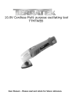
USER MANUAL - EN
IN 8056 Magnetic Upright Bike inSPORTline Yanti
1
CONTENTS
IMPORTANT SAFETY INSTRUCTIONS ............................................................................................................ 3
PARTS LIST ........................................................................................................................................................... 4
HARDWARE PACKING LIST.......................................................................................................................... 6
TOOLS ................................................................................................................................................................ 6
OVERVIEW DRAWING ....................................................................................................................................... 7
ASSEMBLY INSTRUCTIONS .............................................................................................................................. 8
STEP 1: FRONT/REAR STABILIZERS AND RIGHT/LEFT FOOT PEDALS INSTALLATION ................. 8
STEP 2: SEAT POST, SEAT POST BELLOWS, AND SEAT CUSHION INSTALLATION ......................... 9
STEP 3: HANDLEBAR POST INSTALLATION ........................................................................................... 10
STEP 4: HANDLEBAR AND COMPUTER INSTALLATION ...................................................................... 11
OPERATING THE COMPUTER ......................................................................................................................... 12
ADJUSTMENTS .................................................................................................................................................. 13
ADJUSTING THE TENSION CONTROL KNOB .......................................................................................... 13
ADJUSTING THE REAR STABILIZER END CAP ....................................................................................... 13
ADJUSTING THE SEAT HEIGHT ................................................................................................................. 13
MAINTENANCE ................................................................................................................................................. 14
CLEANING ...................................................................................................................................................... 14
STORAGE ........................................................................................................................................................ 14
TROUBLESHOOTING ........................................................................................................................................ 14
WARM UP AND COOL DOWN ROUTINE ...................................................................................................... 14
TERMS AND CONDITIONS OF WARRANTY, WARRANTY CLAIMS ....................................................... 17
2
IMPORTANT: Read all instructions carefully before using this product.
owner’s manual for future reference.
Retain this
The specifications of this product may vary from this photo, subject to change without
notice.
IMPORTANT SAFETY INSTRUCTIONS
Basic precautions should always be followed, including the following important safety instructions when
using this equipment. Read all instructions before using this equipment.
1. Read all instructions and follow it carefully before using this equipment. Make sure the equipment is
properly assembled and tightened before use.
2. Before exercise, in order to avoid injuring the muscle, warm-up exercises are recommended.
3. Please make sure all parts are not damaged and fixed well before use. This equipment should be placed
on a flat surface when using. Using a mat or other covering material on the ground is recommended.
4. Please wear proper clothes and shoes when using this equipment; do not wear clothes that may catch
any part of the equipment; remember to tighten the pedaling straps.
5. Do not attempt any maintenance or adjustments other than those described in this manual. Should any
problems arise, discontinue use and consult your local dealer.
6. Do not use the equipment outdoors.
7. This equipment is for household use only. It is not a commercial model.
8. Only one person at a time should use this equipment.
9. If you feel any chest pains, nausea, dizziness, or short of breath, you should stop exercising immediately
and consult your physician before continuing.
10. Care should be taken in mounting or dismounting the equipment.
11. Do not allow children to use or play on the equipment. Keep children and pets away from the
equipment while in use. This machine is designed for adults use only. The minimum free space
required for safe operation is not less than two meters.
12. The maximum weight capacity for this product is 110 kgs.
WARNING: Before beginning any exercise program consult your physician. This is especially important
for the people who are over 35 years old or who have pre-existing health problems. Read all instructions
before using any fitness equipment.
CAUTION: Read all instructions carefully before operating this product. Retain this Owner’s Manual for
future reference.
3
PARTS LIST
No.
Description
Qty
001
Main Frame Ø50x1.5t
1
002
Handlebar Ø25x1.5t
1
003
Handlebar Post L650xØ50
1
004
Rear Stabilizer Ø50x1.5x380mm
1
005
Flywheel Ø230
1
006
Front Stabilizer Ø50x1.5x360mm
1
007
Tension Control Knob L=500
1
008
Seat Post Knob M16x1.5
1
009
Belt 280J4
1
010
Computer
1
011
Wave Washer
1
012
Seat Post Bushing
1
013
Left Cover
1
014
Right Cover
1
015
Cross Recessed Pan Head Tapping Screw ST3x10
2
016
Washer Ø34.5x23x2.5t
1
017
Bearing Nut I 15/16"
1
018
Hexagon Nut 7/8"
1
019
Belt Pulley with Crank 200J6
1
020
Left Foot Pedal JD-12A
1
021
Right Foot Pedal JD-12A
1
022
Bearing Cup
2
023
Ball Bearing
2
024
Hexagon Socket Pan Head Cap Bolt M8x16
6
025
Seat Post 545x20x1.5t
1
026
Sensor with Wire L=550mm
1
027
Seat Cushion DD-98-2AT
1
028
Front Stabilizer End Cap Ø50
2
029
Rear Stabilizer End Cap Ø50
2
030
Small Bearing
2
031
Spring Clip
1
032
Seat Post Bellows
1
033
Extension Sensor Wire L=1100mm
1
034
Cap Nut M10
4
035
Carriage Bolt M10x60
4
4
036
Big Curve Washer Ø10
4
037
Curve Washer Ø18xØ8x1.5t
6
038
Washer Ø18xØ8x1.5t
4
039
Big Spring
1
040
Cross Recessed Pan Head Tapping Screw ST4x16
12
041
Small Spring
1
042
Nylon Nut M8
4
043
Hexagon Bolt M5x30
1
044
Idler Arm
1
045
Bearing 6000-2Z
2
046
Big Washer Ø5xØ20x1.5t
1
047
Cross Recessed Pan Head Bolt M4x12
2
048
Washer Ø24xØ40x3t
1
049
Handlebar End Cap Ø25
2
050
Handlebar Foam Grip Ø30xØ24x455
2
051
Cross Recessed Pan Head Tapping Screw ST4.2x20
2
052
Cross Recessed Pan Head Bolt M6x10
1
053
Hand Pulse Sensor with Wire L=750mm
2
054
Tension Cable L=1150mm
1
055
Washer Ø12xØ6x1.5t
1
056
Washer Ø10.2xØ14x1t
1
057
Cross Recessed Pan Head Bolt M5x45
1
058
Bearing Nut II 13/16"
1
059
Axle
1
060
Cover Cap Ø60xØ27xT7
2
061
Magnet Bracket
1
062
Washer Ø10xØ5.5xT1.5
1
063
Cross Recessed Pan Head Bolt M5x8
1
064
Magnet
3
065
Hexagon Nut M5
2
5
HARDWARE PACKING LIST
(34) Cap Nut M10
(35) Carriage Bolt M10x60
4 PCS
4 PCS
(8) Seat Post Knob M16x1.5
1 PC
(36) Big Curve Washer Ø10
4 PCS
TOOLS
Multi Hex Tool
5mm Allen Wrench with Phillips Screwdriver
1 PC
1 PC
6
OVERVIEW DRAWING
7
ASSEMBLY INSTRUCTIONS
STEP 1: FRONT/REAR STABILIZERS AND RIGHT/LEFT FOOT PEDALS
INSTALLATION
Tool:
Multi Hex Tool
Hardware:
(34) Cap Nut M10
4 PCS
(35) Carriage Bolt M10x60
4 PCS
(36) Big Curve Washer Ø10
4 PCS
STABILIZERS INSTALLATION
Position the Front Stabilizer (6) in front of the Main Frame (1) and align bolt holes. Attach the Front Stabilizer
(6) onto the front curve of the Main Frame (1) with two M10 Cap Nuts (34), two M10x60 Carriage Bolts (35),
and two Ø10 Big Curve Washers (36). Tighten cap nuts with the Multi Hex Tool provided.
Position the Rear Stabilizer (4) behind the Main Frame (1) and align bolt holes. Attach the Rear Stabilizer (4)
onto the rear curve of the Main Frame (1) with two M10 Cap Nuts (34), two M10x60 Carriage Bolts (35), and
two Ø10 Big Curve Washers (36). Tighten cap nuts with the Multi Hex Tool provided.
FOOT PEDALS INSTALLATION
The Pedal Shafts and Pedals are marked “R” for Right and “L” for Left.
Insert the pedal shaft of Left Foot Pedal (20) into threaded hole in the left Crank (19). Turn the pedal shaft by
hand in the counter-clockwise direction until snug.
Note: DO NOT turn the pedal shaft in the clockwise direction, doing so will strip the threads.
Tighten the pedal shaft of Left Foot Pedal (20) with the Multi Hex Tool provided.
Insert pedal shaft of Right Foot Pedal (21) into threaded hole in right Crank (19). Turn the pedal shaft by hand
in the clockwise direction until snug. Tighten pedal shaft of Right Foot Pedal (21) with the Multi Hex Tool
provided.
8
STEP 2: SEAT
INSTALLATION
POST,
SEAT
POST
BELLOWS,
AND SEAT
CUSHION
Tool:
Multi Hex Tool
Hardware:
(8) Seat Post Knob M16x1.5
1 PC
Remove three Ø18xØ8x1.5t Washers (38) and three M8 Nylon Nuts (42) from underside of the Seat Cushion
(27). Remove nylon nuts with the Multi Hex Tool provided.
Guide bolts on underside of the Seat Cushion (27) through holes on top of the Seat Post (25), attach with three
removed Ø18xØ8x1.5t Washers (38) and M8 Nylon Nuts (42). Tighten nylon nuts with the Multi Hex Tool
provided.
Slide Seat Post Bellows (32) up onto the Seat Post (25).
Insert the Seat Post (25) into the Seat Post Bushing (12) on the tube of the Main Frame (1) and then attach the
M16x1.5 Seat Post Knob (8) onto the tube of the Main Frame (1) by turning it in a clockwise direction to lock
the Seat Post (25) in the suitable position.
9
STEP 3: HANDLEBAR POST INSTALLATION
Tool:
5mm Allen Wrench with Phillips Screwdriver
Remove four M8x16 Hexagon Socket Pan Head Cap Bolts (24) and four Ø18xØ8x1.5t Curve Washers (37) from
the Main Frame (1). Remove bolts with the 5mm Allen Wrench with Phillips Screwdriver provided.
Connect the Sensor Wire (26) from the Main Frame (1) to the Extension Sensor Wire (33) from the Handlebar
Post (3). It is recommended to have a second person assist with this step. One person should hold the Handlebar
Post (3) in place while the other person connects the sensor wires.
Put the cable end of resistance cable of Tension Control Knob (7) into the cable lock of Tension Cable (54), see
Figure A.
Pull the resistance cable of Tension Control Knob (7) up and force it into the slot of metal bracket of Tension
Cable (54), see Figure B.
Insert the metal fitting on the resistance cable of Tension Control Knob (7) into the hole at the end of the slot in
the metal bracket of Tension Cable (54), see Figure C.
Connect the resistance cable of Tension Control Knob (7) to Tension Cable (54) complete, see Figure D.
Carefully tuck wires into Main Frame (1) while sliding Handlebar Post (3) onto the tube of the Main Frame (1)
and secure with four M8x16 Hexagon Socket Pan Head Cap Bolts (24) and four Ø18xØ8x1.5t Curve Washers
(37) that were removed.
PLEASE FOLLOW THIS PROCEDURE TO TIGHTEN BOLTS WITH THE 5MM ALLEN WRENCH WITH
PHILLIPS SCREWDRIVER PROVIDED:
Tighten two M8x16 Hexagon Socket Pan Head Cap Bolts (24) in front of the Main Frame (1) first then the other
two M8x16 Hexagon Socket Pan Head Cap Bolts (24) on the side to secure the Handlebar Post (3) successfully.
10
STEP 4: HANDLEBAR AND COMPUTER INSTALLATION
Tool:
5mm Allen Wrench with Phillips Screwdriver
Remove two M8x16 Hexagon Socket Pan Head Cap Bolts (24) and two Ø18xØ8x1.5t Curve Washers (37) from
the Handlebar Post (3). Remove bolts with the 5mm Allen Wrench with Phillips Screwdriver provided.
Insert the Hand Pulse Sensor Wires (53) into the hole on the Handlebar Post (3) and then pull the Hand Pulse
Sensor Wires (53) out from the top end of the Handlebar Post (3).
Attach the Handlebar (2) onto the Handlebar Post (3) with two M8x16 Hexagon Socket Pan Head Cap Bolts (24)
and two Ø18xØ8x1.5t Curve Washers (37) that were removed. Tighten bolts with the 5mm Allen Wrench with
Phillips Screwdriver provided.
Remove two M4x12 Cross Recessed Pan Head Bolts (47) from the Computer (10). Remove bolts with the 5mm
Allen Wrench with Phillips Screwdriver provided.
Connect the Extension Sensor Wire (33) and Hand Pulse Sensor Wires (53) to the wires that come from the
Computer (10). Tuck wires into the Handlebar Post (3). Attach the Computer (10) onto the top end of the
Handlebar Post (3) with two M4x12 Cross Recessed Pan Head Bolts (47) that were removed. Tighten bolts with
the 5mm Allen Wrench with Phillips Screwdriver provided.
11
OPERATING THE COMPUTER
Computer Image for Item No. IN8056-2
Computer Image for Item No. IN8056-1
USING YOUR COMPUTER
The computer can be activated by pressing the MODE button or by pedaling. If you leave the equipment idle for
4-5 minutes, the power will turn off automatically.
BUTTON FUNCTIONS
Press the MODE button to select one of the functions of the computer.
Press and hold the MODE button for 3 seconds to reset all data values to zero except the ODO (ODOMETER)
data values.
COMPUTER FUNCTIONS
SCAN
Automatically scans each function in sequence with change every 5 seconds.
NOTE: If you do not want to use the SCAN function, press the button to select
one of the other functions.
TMR (TIMER)
Displays your elapsed workout time in minutes and seconds.
KM (SPEED)
Displays the current training speed.
CAL (CALORIES)
Displays approximate amount of calories burned during workout.
(This data is a rough guide for comparison of different exercise sessions and
should not be used in medical treatment).
P (PULSE)
Displays your current heart rate figures after you grip the handlebar pulse sensors
with both your hands during exercise. To ensure the pulse readout is more
precise, please always hold on to the handlebar pulse sensors with both hands
instead of just with one hand when you try to test your heart rate figures.
DIS (DISTANCE)
Displays the cumulative distance traveled during workout.
ODO (ODOMETER)
Displays the total accumulative distance traveled. The ODOMETER data values
cannot be clear to zero by pressing and holding the button for 3 seconds. If you
take out the batteries from the computer, the ODOMETER data values will clear
12
to zero.
HOW TO INSTALL THE BATTERIES
1. Remove the battery cover on the back of the computer.
2. Place two size AAA batteries into the battery housing.
3. Insure batteries are correctly positioned and battery springs are in proper contact with batteries.
4. Re-install the battery cover.
5. If the display is illegible or only partial segment appears, remove batteries and wait 15 seconds before
reinstalling.
ADJUSTMENTS
ADJUSTING THE TENSION CONTROL KNOB
To increase the tension, turn the tension control knob in a clockwise direction. To decrease the tension, turn the
tension control knob in a counterclockwise direction.
ADJUSTING THE REAR STABILIZER END CAP
Turn the rear stabilizer end cap on the rear stabilizer as needed to level the upright bike.
ADJUSTING THE SEAT HEIGHT
Turn the seat post knob in a counterclockwise direction until the seat post can be slid up or down and then slide
the seat post up or down direction to the suitable position. Lock the seat post in place by tightening the seat post
knob in a clockwise direction.
NOTE: When adjusting the height of seat post, make sure the seat post bushing does not exceed the mark line on
the seat post.
13
MAINTENANCE
CLEANING
The upright bike can be cleaned with a soft clean damp cloth. Do not use abrasives or solvents on plastic parts.
Please wipe your perspiration off the upright bike after each use. Be careful not to get excessive moisture on the
computer display panel as this might cause an electrical hazard or electronics to fail. Please keep the upright
bike, especially the computer console out of direct sunlight to prevent screen damage.
Please inspect all assembly bolts, nuts, screws, and pedals on the machine for proper tightness every week.
STORAGE
Store the upright bike in a clean and dry environment away from children.
TROUBLESHOOTING
PROBLEM
SOLUTION
The upright bike wobbles
when in use.
Turn the rear stabilizer end cap on the rear stabilizer as needed to level the
upright bike.
1. Remove the computer console and verify the wires that come from the
computer console are properly connected to the wires that come from the
handlebar post.
There is no display on the
computer console.
2. Check if the batteries are correctly positioned and battery springs are in
proper contact with batteries.
3. The batteries in the computer console may be dead. Replace with new
batteries.
1. Make sure that the wire connections for the hand pulse sensors are secure.
There is no heart-rate reading
or there is erratic /
inconsistent reading.
2. To ensure the pulse readout is more precise, please always hold on to the
handlebar grip sensors with both hands instead of just with one hand when
you try to test your heart rate figures.
3. Avoid gripping the hand pulse sensors too tight. Try to maintain moderate
pressure while holding onto the hand pulse sensors.
The upright bike makes a
squeaking noise when in use.
The bolts may be loose on the upright bike.
Please inspect all of the bolts and tighten any loose bolts.
WARM UP AND COOL DOWN ROUTINE
The WARM-UP is an important part of any workout. The purpose of warming up is to prepare your body for
exercise and to minimize injuries. Warm up for two to five minutes before aerobic exercising. It should begin
every session to prepare your body for more strenuous exercise by heating up and stretching your muscles,
increasing your circulation and pulse rate, and delivering more oxygen to your muscles.
COOL DOWN at the end of your workout, repeat these exercises to reduce soreness in tired muscles. The
purpose of cooling down is to return the body to its resting state at the end of each exercise session. A proper
cool-down slowly lowers your heart rate and allows blood to return to the heart.
HEAD ROLLS
Rotate your head to the right for one count, you should feel a stretching sensation up the left side of your neck.
Then rotate your head back for one count, stretching your chin to the ceiling and letting your mouth open.
Rotate your head to the left for one count, then drop your head to your chest for one count.
14
SHOULDER LIFTS
Lift your right shoulder toward your ear for one count. Then lift your left shoulder up for one count as you lower
your right shoulder.
SIDE STRETCHES
Open your arms to the side and lift them until they are over your head. Reach your right arm as far toward the
ceiling as you can for one count. Repeat this action with your left arm.
QUADRICEPS STRETCH
With one hand against a wall for balance, reach behind you and pull your right foot up. Bring your heel as close
to your buttocks as possible. Hold for 15 counts and repeat with left foot.
15
INNER THIGH STRETCH
Sit with the soles of your feet together and your knees pointing outward. Pull your feet as close to your groin as
possible. Gently push your knees toward the floor. Hold for 15 counts.
TOE TOUCHES
Slowly bend forward from your waist, letting your back and shoulders relax as you stretch toward your toes.
Reach as far as you can and hold for 15 counts.
HAMSTRING STRETCHES
Extend your right leg. Rest the sole of your left foot against your right inner thigh. Stretch toward your toe as
far as possible. Hold for 15 counts. Relax and then repeat with left leg.
16
CALF/ACHILLES STRETCH
Lean against a wall with your left leg in front of the right and your arms forward. Keep your right leg straight
and the left foot on the floor; then bend the left leg and lean forward by moving your hips toward the wall. Hold,
then repeat on the other side for 15 counts.
TERMS AND CONDITIONS OF WARRANTY, WARRANTY CLAIMS
General Conditions of Warranty and Definition of Terms
All Warranty Conditions stated hereunder determine Warranty Coverage and Warranty Claim Procedure.
Conditions of Warranty and Warranty Claims are governed by Act No. 40/1964 Coll. Civil Code, Act No.
513/1991 Coll., Commercial Code, and Act No. 634/1992 Coll., Consumer Protection Act, as amended, also in
cases that are not specified by these Warranty rules.
The seller is SEVEN SPORT s.r.o. with its registered office in Borivojova Street 35/878, Prague 13000,
Company Registration Number: 26847264, registered in the Trade Register at Regional Court in Prague, Section
C, Insert No. 116888.
According to valid legal regulations it depends whether the Buyer is the End Customer or not.
“The Buyer who is the End Customer” or simply the “End Customer” is the legal entity that does not conclude
and execute the Contract in order to run or promote his own trade or business activities.
“The Buyer who is not the End Customer” is a Businessman that buys Goods or uses services for the purpose of
using the Goods or services for his own business activities. The Buyer conforms to the General Purchase
Agreement and business conditions to the extent specified in the Commercial Code.
These Conditions of Warranty and Warranty Claims are an integral part of every Purchase Agreement made
between the Seller and the Buyer. All Warranty Conditions are valid and binding, unless otherwise specified in
the Purchase Agreement, in the Amendment to this Contract or in another written agreement.
Warranty Conditions
Warranty Period
The Seller provides the Buyer a 24 months Warranty for Goods Quality, unless otherwise specified in the
Certificate of Warranty, Invoice, Bill of Delivery or other documents related to the Goods. The legal warranty
period provided to the Consumer is not affected.
17
By the Warranty for Goods Quality, the Seller guarantees that the delivered Goods shall be, for a certain period
of time, suitable for regular or contracted use, and that the Goods shall maintain its regular or contracted
features.
The Warranty does not cover defects resulting from:
User’s fault, i.e. product damage caused by unqualified repair work, improper assembly, insufficient insertion of
seat post into frame, insufficient tightening of pedals and cranks
Improper maintenance
Mechanical damages
Regular use (e.g. wearing out of rubber and plastic parts, joints etc.)
Unavoidable event, natural disaster
Adjustments made by unqualified person
Improper maintenance, improper placement, damages caused by low or high temperature, water, inappropriate
pressure, shocks, intentional changes in design or construction etc.
Warranty Claim Procedure
The Buyer is obliged to check the Goods delivered by the Seller immediately after taking the responsibility for
the Goods and its damages, i.e. immediately after its delivery. The Buyer must check the Goods so that he
discovers all the defects that can be discovered by such check.
When making a Warranty Claim the Buyer is obliged, on request of the Seller, to prove the purchase and validity
of the claim by the Invoice or Bill of Delivery that includes the product’s serial number, or eventually by the
documents without the serial number. If the Buyer does not prove the validity of the Warranty Claim by these
documents, the Seller has the right to reject the Warranty Claim.
If the Buyer gives notice of a defect that is not covered by the Warranty (e.g. in the case that the Warranty
Conditions were not fulfilled or in the case of reporting the defect by mistake etc.), the Seller is eligible to
require a compensation for all the costs arising from the repair. The cost shall be calculated according to the
valid price list of services and transport costs.
If the Seller finds out (by testing) that the product is not damaged, the Warranty Claim is not accepted. The
Seller reserves the right to claim a compensation for costs arising from the false Warranty Claim.
In case the Buyer makes a claim about the Goods that is legally covered by the Warranty provided by the Seller,
the Seller shall fix the reported defects by means of repair or by the exchange of the damaged part or product for
a new one. Based on the agreement of the Buyer, the Seller has the right to exchange the defected Goods for a
fully compatible Goods of the same or better technical characteristics. The Seller is entitled to choose the form of
the Warranty Claim Procedures described in this paragraph.
The Seller shall settle the Warranty Claim within 30 days after the delivery of the defective Goods, unless a
longer period has been agreed upon. The day when the repaired or exchanged Goods is handed over to the Buyer
is considered to be the day of the Warranty Claim settlement. When the Seller is not able to settle the Warranty
Claim within the agreed period due to the specific nature of the Goods defect, he and the Buyer shall make an
agreement about an alternative solution. In case such agreement is not made, the Seller is obliged to provide the
Buyer with a financial compensation in the form of a refund.
SEVEN SPORT, s.r.o.
Borivojova 35/878 130 00 Praha 3, Czech Rebublic
CRN: 268 47 264, VAT ID: CZ26847264
Orders:
+420 556 300 970,
[email protected]
Warranty Claims:
+420 556 770 190, Mobile: +420 604 853 019,
[email protected]
Service:
+420 556 770 190, Mobile: +420 604 853 019,
[email protected]
Fax:
+420 556 770 192, (Service +420 556 770 191)
Web:
www.insportline.cz, www.worker.cz, www.worker-moto.cz
18
INSPORTLINE, s.r.o.
Bratislavska 36, 911 05 Trencin, Slovakia
CRN: 36311723, VAT ID: SK2020177082
Orders:
+421(0)326 526 701, +421(0)917 649 192,
[email protected]
Warranty Claims:
+421(0)326 526 701, +421(0)918 408 519,
[email protected]
Fax:
+421(0)326 526 705
Web:
www.insportline.sk, www.worker.sk, www.worker-moto.sk
Date of Sale:
Stamp and Signature of Seller:
19