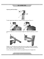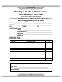
1
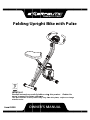
Fo
oldin
ng Uprig
ght Bike
B
with
w Pulsse
IMPO
ORTANT:
Read
d all instru
uctions carefully beffore using
g this prod
duct.
owne
er’s manual for futu
ure referen
nce.
Rettain this
The s
specificatio
ons of this product m
may vary fro
om this pho
oto, subjecct to chang
ge
witho
out notice.
Item
m #1200 OW
WNER
R’S M
MANUAL 1200.2‐101414 TABLE OF CONTENTS
SERVICE ------------------------------------------------------------------------ 2
LABEL PLACEMENT --------------------------------------------------------- 3
PRODUCT SAFETY ---------------------------------------------------------- 4
OVERVIEW DRAWING ------------------------------------------------------ 5
PARTS LIST --------------------------------------------------------------------- 6
HARDWARE LIST & TOOLS ----------------------------------------------- 8
ASSEMBLY --------------------------------------------------------------------- 9
COMPUTER --------------------------------------------------------------------- 13
STORAGE ----------------------------------------------------------------------- 14
ADJUSTMENTS --------------------------------------------------------------- 15
TROUBLE SHOOTING & MAINTENANCE ---------------------------- 17
WARM UP ---------------------------------------------------------------------- 18
WARRANTY -------------------------------------------------------------------- 19
FAX FORM ---------------------------------------------------------------------- 20
1
SERVICE
IMPORTANT: FOR NORTH AMERICA ONLY
To request product service and order
replacement parts, please call our
customer service department at:
1-844-641-7921
Monday through Friday, 8:00 AM-5:00 PM Pacific Standard Time,
or email us at: [email protected]
Please visit our website at www.paradigmhw.com.
Please have the following information ready when requesting for service:
Your name
Phone number
Model number
Serial number
Part number
Proof of Purchase
*Before returning this product to the store please contact
customer service at the contact number.
Paradigm Health & Wellness, Inc.
1189 Jellick Ave.
City of Industry, CA 91748, USA
2
LABELL PLACEM
MENT
3
PRODUCT SAFETY
Basic precautions should always be followed, including the following
safety instructions when using this equipment. Read all instructions
before using this equipment.
1.
Read all the instructions in this manual and do warm up exercises before
using this equipment.
2. Before exercise, in order to avoid injuring the muscle, warm-up exercise
of every position of the body is necessary. Refer to Warm Up pages.
After exercise, relaxation of the body is suggested for cool-down.
3. Please make sure all parts are not damaged and fixed well before use.
This equipment should be placed on a flat surface when using. Using a
mat or other covering material on the ground is recommended.
4. Please wear proper clothes and shoes when using this equipment; do not
wear clothes that might catch any part of the equipment; remember to
tighten the pedaling straps.
5. Do not attempt any maintenance or adjustments other than those
described in this manual. Should any problems arise, discontinue use
and consult an Authorized Service Representative.
6. Do not use the equipment outdoors.
7. This equipment is for household use only.
8. Only one person should be on the equipment while in use.
9. Keep children and pets away from the equipment while in use. This
machine is designed for adults only. This product requires a minimum of
6 feet of space for safe operation.
10. If you feel any chest pains, nausea, dizziness, or short of breath, you
should stop exercising immediately and consult your physician before
continuing.
11. The maximum weight capacity for this product is 300 lbs / 136kgs.
WARNING: Before beginning any exercise program consult
your physician. This is especially important for the people who are
over 35 years old or who have pre-existing health problems. Read all
instructions before using any fitness equipment.
CAUTION: Read all instructions carefully before operating this
product.
Retain this Owner’s Manual for future reference.
4
OVERVIEW DRAWING
77
82
17
4
9
79
36
83
10
73 74 73
16
66
7
26
25
27
6
86
23
61
42
58
18
13
60
33
33 34
67
57
21 16
42
27
59
21
51 64
43
39
84R
24
64
51
44
72
3
31
45 84L
47
48
50
11
20
14
43
81
40
22 63 85 80
42
35
37
61
32
60
58
65 56
54 52
70
29
55
30
49
29
30
71
68
38
42
21
1
78
53
69
2
78
76
5
40
43
43
12
17
15
43
62
28
33
58
75
74
73
45
47
48
50
27
46
32
19
87
8
11
5
25
26
PARTS LIST
No.
Description
Qty No.
Description
Qty
001 Rear Frame
1
029 Hexagon Nut Cap M8
4
002 Front Frame
1
030 Curve Washer Ø8.2xØ22.2
4
003 Rear Stabilizer Ø50x1.5tx550L
1
031 Front Stabilizer Ø50x1.5tx550L
1
004 Handlebar Ø25
1
032 C-ring Ø10
2
005 Seat Post
1
033 Flat Washer Ø8.2xØ16.8
5
006 Seat Cushion
1
034 Nylon Nut M8
1
007 Left Pedal (YH-30X)
1
035 Magnet Bracket
1
008 Right Pedal (YH-30X)
1
036 Washer Ø6.2
2
009 Computer (81414)
1
037 Sensor with Wire
1
010 Wire Plug (15x9)
1
038 Flywheel
1
011
2
039 Belt Wheel with Crank Axle
1
012 Seat Post Plastic Bushing
1
040 Bearing Bracket A
2
013 Tension Control Knob (1080L)
1
042 Bearing 6003RS
4
Seat Height Adjustment Knob
M16
1
043 C-ring Ø17
6
015 Sensor Wire (900L)
1
044 Belt Wheel
1
016 Oval Wire Plug
4
045 Bearing 6000Z
2
2
046 Axle Ø12.8x94L
1
018 Left Shroud
1
047 Eyebolt M6
2
019 Right Shroud
1
048 Tension Bracket
2
020 Top Shroud
1
049 Front Frame Support Tube Holder
1
021 Round Plastic Bushing
6
050 Nylon Nut M6
2
022 Safety Pin Ø10x110L
1
051 Nut M10
3
023 Left Crank
1
052 Washer Ø10.2xØ25
1
024 Right Crank
1
053 Wave Washer Ø17
1
025 France Nut
2
054 Idle Wheel Axle
1
026 Crank Cover
2
055 Nylon Nut M10
1
014
017
Rear Stabilizer End Cap
Handlebar Foam Grip
Ø23x5.0tx420L
027
Round Phillips Head Drilling
Screw M4x20
7
056 Bearing 6902Z
2
028
Round Phillips Head Tapping
Screw M4x20
4
057 Axle Ø15.8x94.5L
1
6
PARTS LIST
No.
Description
Qty No.
Description
Qty
058 Hexagon Socket Bolt M8x15
5
074 Spring Washer Ø6.2
4
059 Rubber Cushion
1
075 Screw M5x15
2
060 Washer Ø8.2x Ø25x2.0t
2
076 Hexagon Socket Bolt M8x40L
1
061 Flat Phillips Head Screw M6x10
6
077 Handlebar End Cap Ø25.4
2
062 Holder
1
078
1
079 Hand Pulse Sensor Wire
2
064 Plastic Washer
2
080 Nut M6
1
065 C-ring Ø15
1
081 Screw M6x15
1
066 Screw M4x10L
2
082 Hand Pulse Sensor
2
067 Front Frame Support Tube
1
083
068 Screw M5x20
1
084R Front Stabilizer Right End Cap
1
069 Washer Ø5.2xØ18
1
084L Front Stabilizer Left End Cap
1
070 Spring
1
085 Spring Washer M6
1
071 Belt 240J4
1
086 Nylon Nut 9/16 UNC12(L)
1
072 Belt 230J3
1
087 Nylon Nut 9/16 UNC12(R)
1
073 Hexagon Socket Bolt M6x12
4
063
Round Phillips Head Screw
M4x10
7
Front Frame Support Tube End
Cap Ø22.2
Countersunk Phillips Head Cap
Screw M4x20
3
2
HARDWARE LIST & TOOLS
(14) Seat Height
Adjustment Knob
1 PC
(22) Safety Pin
1 PC
(29) Hexagon Nut Cap
4 PCS
(30) Curve Washer
4 PCS
(33) Flat Washer
3 PCS
(58) Hexagon Socket Bolt
3 PCS
(66) Screw
2 PCS
(73) Hexagon Socket Bolt
4 PCS
Wrench 13-15
1 PCS
Allen Wrench with
Phillips Screwdriver
1 PCS
8
(74) Spring Washer
4 PCS
Wrench 19MM
1 PCS
ASSSEMBLLY
2
22
Tool:
29
30
29
30
3
Wrench 13-15
31
1
Front Stab
bilizer (31)
Transporrt Wheel
Rea
ar Stabilize
er (3)
Step 1
Stand up the base
b
of the
e machine by separa
ating the Rear and Frront Frame
es
(1, 2
2). Pull th
he Rear an
nd Front Frrames (1, 2)
2 apart fro
om each otther. Align pin
hole
es for inserrting the Safety Pin ((22) then in
nsert the Safety Pin ((22) into th
he
hole
es on the Rear
R
and Front
F
Fram
mes (1, 2) to
o lock the frames
f
in pplace.
Atta
ach the Fro
ont Stabiliz
zer (31) witth the trans
sport whee
els onto thee Front Fra
ame
(2) w
with two Hexagon
H
Nu
uts Cap (2 9) and two
o Curve Wa
ashers (300). Tighten nut
cap
ps with the Wrench prrovided.
Atta
ach the Rear Stabilize
er (3) onto
o the Rear Frame (1) with two H
Hexagon Nuts
N
Cap
p (29) and two Curve
e Washers (30). Tighten nut ca
aps with thhe Wrench
provvided.
Hardware:
(22
2) Safety Pin
P
1 PC
(29) Hexxagon Nutt Cap
4 PCS
9
(30) Cuurve Wash
her
4 PCS
ASSEMBLY
Tool:
Wrench 13-15
Tool:
86
Wrench 19MM
1 PCS
Step 2
Loosen Nylon Nut (L)(86) and Nylon Nut (R)(87) from Left and Right Pedal (7)
&(8) first.
The Cranks, Pedals, Pedal Shafts and Pedal Straps are marked “R” for
Right and “L” for Left.
Insert the pedal shaft of Left Pedal (7) into threaded hole in the Left Crank (23).
Turn the pedal shaft by hand in the counter-clockwise direction until snug.
Note: DO NOT turn the pedal shaft in the clockwise direction, doing so will
strip the threads.
Tighten the pedal shaft of Left Pedal (7) with the Wrench 13-15 provided, then
tighten Nylon Nut (L)(86) with the Wrench 19mm provided.
Insert pedal shaft of Right Pedal (8) into threaded hole in Right Crank (24).
Turn the pedal shaft by hand in the clockwise direction until snug.
Tighten pedal shaft of Right Pedal (8) with the Wrench provided, then tighten
Nylon Nut (R)(87) with the Wrench 19mm provided.
10
ASSEMBLY
Tool:
Allen Wrench
Phillips Screwdriver
Allen Wrench with Phillips
Screwdriver
Step 3
Align bolt holes on underside of Seat Cushion (6) with holes on top of Seat Post
(5), then attach with three Flat Washers (33) and three Hexagon Socket Bolts
(58). Tighten bolts with the Allen Wrench provided.
Insert the Seat Post (5) into Seat Post Plastic Bushing (12). Adjust seat
position and insert the Seat Height Adjustment Knob (14). Turn the Seat
Height Adjustment Knob (14) in a clockwise direction to tighten.
Hardware:
(14) Seat Height
Adjustment Knob
1 PC
(33) Flat Washer
3 PCS
11
(58) Hexagon Socket Bolt
3 PCS
ASSEMBLY
Allen Wrench
Tool:
Phillips Screwdriver
Allen Wrench with Phillips
Screwdriver
Step 4
Connect the Sensor Wire (15) from the Rear Frame (1) to the wire that comes
from the Computer (9).
Attach the Handlebar (4) into the Rear Frame (1) with four Hexagon Socket Bolts
(73) and four Spring Washers (74). Tighten bolts with the Allen Wrench
provided.
Attach the Holder (62) onto the Rear Frame (1) with two Screws (66). Tighten
screws with the Phillips Screwdriver provided.
Hardware:
(66) Screw
2 PCS
(73) Hexagon Socket Bolt
4 PCS
12
(74) Spring
Washer
CO
OMPUTEER
SPE
ECIFICATIIONS:
TIM
ME -------------------------------------- -- 0:00-99:59 MIN: SEC
S
SPE
EED ----------------------------------- -- 0.0-999.9 ML/H
DIS
STANCE ---------------------------------- 0.0-999.9 ML
CAL
LORIE -------------------------------- -- 0.0-999.9 KCAL
ODO
OMETER ------------------------------- 0.0-999.9 ML
PUL
LSE --------------------------------------- 40-240 BEATS/MIN
COMPUTER FUNTIONS
S:
TO ON/OF
FF: If you le
eave the ccomputer id
dle for 4 minutes, thee power willl
AUT
shut off autom
matically.
SCA
AN: Press the button
n until the sscreen disp
plays SCA
AN; the com
mputer will
auto
omatically scan the function of TIME, ODOMETER, CALORIE
E, PULSE,
SPE
EED, and DISTANCE
D
E, every 6 seconds.
TIM
ME: Displayys your ela
apsed workkout time in
n minutes and
a secon ds. The
com
mputer will automatica
ally count up from 0:00 to 99:59 in one seecond
inte
ervals.
EED: Displays your workout
w
sp
peed in mile
es per hou
ur.
SPE
DIS
STANCE: Displays
D
the accumullative dista
ance traveled during eeach
worrkout up to a maximu
um of 999.9
9 miles.
CAL
LORIE: Th
he compute
er will estim
mate the cumulative calories buurned at an
ny
give
en time durring your workout.
w
T
The compu
uter will co
ount up from
m 0.0 to
999
9.9 caloriess.
OMETER: Displays the
t total acccumulativ
ve distance
e traveled dduring each
ODO
worrkout up to a maximu
um of 999.9
9 miles. The
T data values of O
ODOMETER
R
can
n not be resset to zero by pressin
ng and holding the bu
utton moree than 2
secconds. If user
u
takes out the ba
atteries from
m the computer, the
ODO
OMETER data value
es will rese
et to zero.
LSE: The computer
c
will
w displayy your puls
se rate in beats per m
minute afterr
PUL
hold
ding both hands
h
on handlebar
h
g
grip sensors during exercise.
e
To ensure
e
the pulse read
dout is morre precise,, please alw
ways hold on to the hhandlebar
p sensors with
w two ha
ands instea
ad of one.
grip
RES
SET: presssing and ho
olding the button more than 2 seconds
s
w
will reset all
funcctional valu
ues to zero
o except th
he odomete
er data values.
HOW
W TO INSTALL THE
E BATTER
RIES:
1. Remove the
t battery
y cover at tthe rear of computer..
o "SIZE-AA
AA" batterie
e battery ho
ousing.
2. Place two
es into the
atteries are
e correctly positioned and battery springs are in
3. Insure ba
proper co
ontact with batteries.
4. Re-installl the batterry cover.
5. If the disp
play is illeg
gible or onl y partial le
egible, remove batterries and wa
ait
15 seconds before reinstalling
g.
13
STORAGE
1
22
2
2
22
1
For your convenience, the bike can be folded up and placed in a storage area.
1. Remove the Safety Pin (22) from the bike.
2. Push the Rear and Front Frames (1, 2) together until they meet.
3. Align pin holes for inserting the Safety Pin (22) then insert the removed
Safety Pin (22) into the holes on the Rear and Front Frames (1, 2) to lock
the frames in place.
14
ADJUSTMENTS
Adjusting the Tension Control Knob
To increase the tension, turn the tension control knob in a clockwise direction.
To decrease the tension, turn the tension control knob in a counterclockwise
direction.
Adjusting the Seat Height
Turn the seat height adjustment knob in a counterclockwise direction until the
seat post can be slid up or down and then slide the seat post up or down
direction to the suitable position. Lock the seat post in place by tightening the
seat height adjustment knob in a clockwise direction.
NOTE: When adjusting the height of seat post, make sure the seat post
plastic bushing does not exceed the mark line on the seat post.
15
ADJUSTMENTS
Adjusting the
e Pedal Sttrap
1
L mark
k
The
e left pedal strap whic
ch has L m
marked on the
t strap (s
see Figuree 1).
2
3
Sna
ap the three
e hole end onto the in
nside edge
e of the leftt pedal (seee Figures 2 and
3).
4
5
Sele
ect one of the adjustment holess which allow your fo
oot to be eaasily remov
ved
from
m the peda
al. Snap the
t other e
end onto the outside edge
e
of thee left peda
al with
the L mark on
n the strap (see Figurres 4 and 5).
5
Use
e the same
e procedure
e to snap tthe right pe
edal strap onto
o
the rigght pedal.
16
MAINTENANCE & TROUBLE SHOOTING
MAINTENANCE
Cleaning
The bike can be cleaned with a soft clean damp cloth. Do not use abrasives or
solvents on plastic parts. Please wipe your perspiration off the bike after each
use. Be careful not to get excessive moisture on the computer display panel as
this might cause an electrical hazard or electronics to fail.
Please keep the bike, especially the computer console out of direct sunlight to
prevent screen damage.
Please inspect all assembly bolts, nuts, screws, and pedals on the machine for
proper tightness every week.
Storage
Store the bike in a clean and dry environment away from children.
TROUBLE SHOOTING
PROBLEM: There is no display on the computer console.
SOLUTION: Remove the computer console and verify the wire that comes from the
computer console are properly connected to the wires that come from the rear
frame.
SOLUTION: Check if the batteries are correctly positioned and battery springs are
in proper contact with batteries.
SOLUTION: The batteries in the computer console may be dead. Replace with
new batteries.
PROBLEM: There is no heart rate reading or heart rate reading is erratic /
inconsistent.
SOLUTION: Make sure that the wire connections for the hand pulse sensors are
secure.
SOLUTION: To ensure the pulse readout is more precise, always hold on to the
handlebar grip sensors with two hands instead of just with one hand only.
SOLUTION: Avoid gripping the hand pulse sensors too tight. Try to maintain
moderate pressure while holding onto the hand pulse sensors.
PROBLEM: The bike makes a squeaking noise when in use.
SOLUTION: The bolts may be loose on the elliptical trainer. Please inspect all of
the bolts and tighten any loose bolts.
17
W
WARM U
UP
Qua
adriceps Stretch
S
With
h one hand
d against a wall for b
balance, reach behind
d
you
u and pull your
y
right fo
oot up. B
Bring your heel
h
as clo
ose
to yyour buttoccks as poss
sible. Holld for 15 co
ounts and
repe
eat with lefft foot up.
Inner Thigh Stretch
S
Sit w
with the so
oles of your feet toge
ether with your
y
knees
poin
nting outwa
ard. Pull your feet a
as close into your gro
oin
as p
possible.
Gen
ntly push your
y
knees towards th
he floor. Hold for 10
0
cou
unts.
Toe
e Touches
s
Slow
wly bend fo
orward from your wa
aist, letting you back and
a
sho
oulders rela
ax as you stretch
s
tow
ward your to
oes. Rea
ach
dow
wn as far as you can and hold ffor 15 coun
nts.
Ham
mstring Sttretches
Sit w
with your right
r
leg ex
xtended. Rest the sole of yourr left
foott against yo
our right in
nner thigh. Stretch toward
t
you
ur
toe as far as possible.
p
Hold for 1 5 counts Relax
R
and then
t
repe
eat with lefft leg exten
nded.
18
WARRANTY
MANUFACTURER’S LIMITED WARRANTY
Paradigm Health & Wellness warrants to the original purchaser that this product is free
from defects in material and workmanship when used for the purpose intended, under the
conditions that it has been installed and operated in accordance with Paradigm’s Owner’s
Manual. Paradigm’s obligation under this warranty applies to the following:
COMPONENT
LENGTH OF WARRANTY
Structural Frame
1 year
All Other Components
90 days
(computer display, electronics, upholstery, foam, ball bearings, pulleys, belts, cables,
wires, shocks, covers, tension, internal mechanism, wheels, pedals, knobs, accessories
and hardware)
Exclusions from Warranty Coverage:
Paradigm does not warrant against and is not responsible for, and no implied warranty shall be deemed to cover, any
product failure, product malfunction, or damages attributable to:
1. Improper installation and/or failure to abide by Paradigm’s installation guidelines;
2. Use of this product beyond normal home use, or in an application for which it was not designed;
3. Cosmetic items such as scratches, dents or discolorations;
4. Damage caused by normal wear and tear, vandalism, accidental or by animals;
5. Any act of Nature (such as fire, flooding, snow, ice, hurricane, earthquake, lightning or other natural disaster),
environmental condition (such as air pollution, mold, mildew, etc.), or staining from foreign substances (such as dirt,
grease, oil, etc.);
6. Normal weathering due to exposure to sunlight, weather and atmosphere which can cause colored surfaces to,
among other things, flake, chalk, accumulate dirt or stains.
7. Improper operation, alteration, handling, storage, abuse or neglect of the products.
Paradigm, using its sole discretion, will either repair or replace free of charge any part(s)
proven to be defective under normal home use. Any repair or replacement shall provide
no new warranty coverage, but shall retain only the remaining portion of the original
product’s warranty. This warranty is offered only to the original purchaser and is not
transferable. Proof of original purchase is required.
Ordering Replacement Parts
Replacement parts can be ordered by calling or emailing our customer service department:
1-844-641-7921
Monday through Friday 8:00 AM - 5:00 PM (PST).
[email protected]
When ordering replacement parts please have the following information ready:
1. Owner’s Manual
2. Model Number
3. Description of Parts
4. Part Number
5. Date of Purchase
19
FAX FORM
Paradigm Health & Wellness, Inc.
PARTS REQUEST FAX FORM
Please fax this form to (1-626-810-2166)
OR YOU CAN EMAIL CUSTOMER SERVICE REQUESTS TO
[email protected]
NAME: _______________________________________________________
ADDRESS: ____________________________________________________
CITY ______________ STATE ______________ ZIP ___________________
TELEPHONE: (Day) _____________________________________________
(Night) ____________________________________________
(Email Address) ____________________________________
SERIAL#: __________________________________________
MODEL#: __________________________________________
PURCHASE DATE: ______________________________________________
PURCHASE FROM: ______________________________________________
PART #
DESCRIPTION
QTY
“YOUR ORDER WILL BE PROCESSED WITHIN 3 BUSINESS DAYS”
OFFICIAL USE ONLY
SHIP DATE: ___________________________________________
TRK #: _______________________________________________
BACK ORDER: ________________________________________
20