1
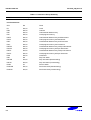
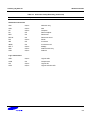
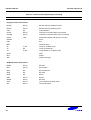
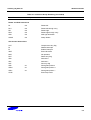
CONTROL REGISTERS
S3F84Q5_UM_REV1.00
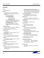
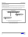
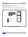
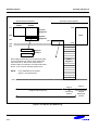
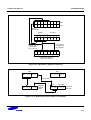
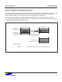
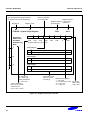
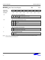
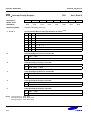
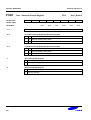
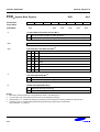
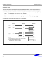
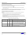
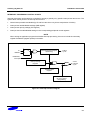
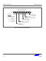
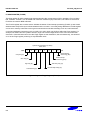
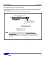
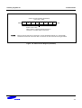
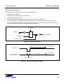
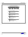
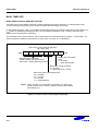
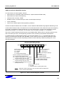
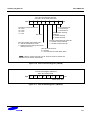
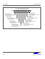
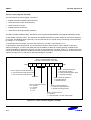
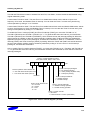
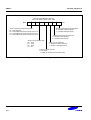
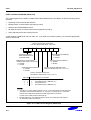
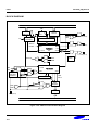
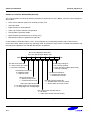
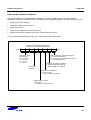
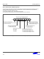
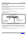
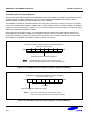
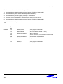
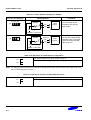
Name of individual
bit or related bits
Bit number(s) that is/are appended to
the register name for bit addressing
Register ID
Register name
Register location
Register address in the internal
register file
(hexadecimal)
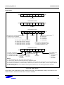
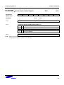
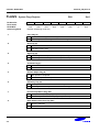
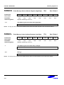
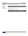
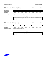
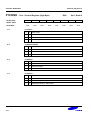
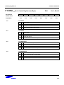
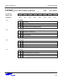
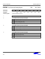
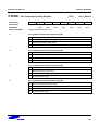
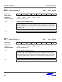
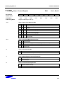
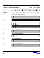
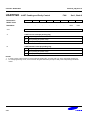
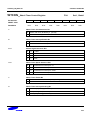
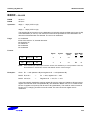
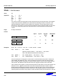
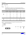
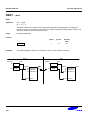
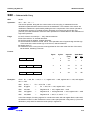
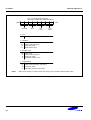
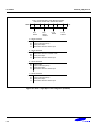
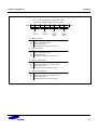
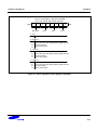
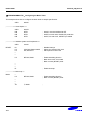
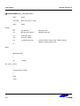
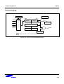
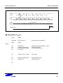
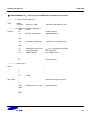
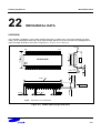
FLAGS - System Flags Register
Bit Identifier
RESET Value
Read/Write
Bit Addressing
.7
.6
D5H
.5
.4
x
x
x
x
R/W
R/W
R/W
R/W
Register addressing mode only
Set 1
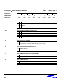
.3
.2
.1
.0
x
R/W
x
R/W
0
R
0
R/W
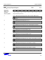
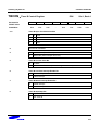
Mode
.7
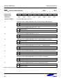
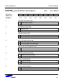
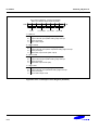
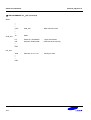
Carry Flag (C)
.6
0
Operation does not generate a carry or borrow condition
0
Operation generates carry-out or borrow into high-order bit 7
Zero Flag (Z)
0
Operation result is a non-zero value
0
Operation result is zero
Sign Flag (S)
.5
0
Operation generates positive number (MSB = "0")
0
Operation generates negative number (MSB = "1")
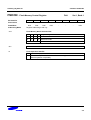
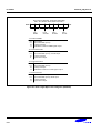
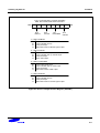
R = Read-only
W = Write-only
R/W = Read/write
'-' = Not used
Type of addressing
that must be used to
address the bit
(1-bit, 4-bit, or 8-bit)
Description of the
effect of specific
bit settings
RESETvalue notation:
'-' = Not used
'x' = Undetermined value Bit number:
MSB = Bit 7
'0' = Logic zero
LSB = Bit 0
'1' = Logic one
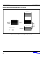
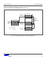
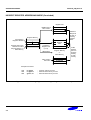
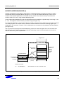
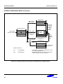
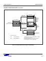
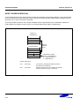
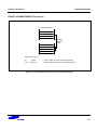
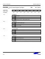
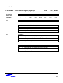
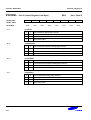
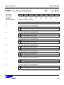
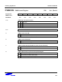
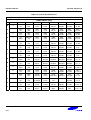
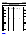
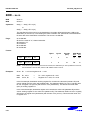
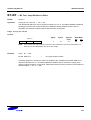
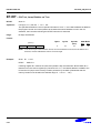
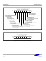
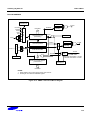
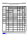
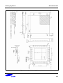
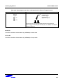
Figure 4-1. Register Description Format
4-4