1
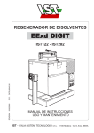
IST-202-A01-MAN REV 1.1 05-05-2014 Page 1 of 20 User Manual IST-201 / IST-202 Hot Cut Over Tool This manual is applicable for all calibrators with model number: IST201-A01-001 and IST202-A01-001 Publication Number: IST-202-A01-MAN, rev 1.1 Edition: 05-05-2014 © Copyright Istec International B.V. Netherlands IST-202-A01-MAN REV 1.1 05-05-2014 Page 2 of 20 Index 1 2 3 4 5 INTRODUCTION ........................................................................................................................ 3 1.1 Purpose............................................................................................................................. 3 1.2 Warnings .......................................................................................................................... 4 1.2.1 Warning symbols .......................................................................................................... 4 1.2.2 Specific warnings .......................................................................................................... 4 1.3 Warranty .......................................................................................................................... 5 QUICK OPERATION ................................................................................................................... 6 2.1 Specifications:................................................................................................................... 7 2.2 Models .............................................................................................................................. 7 OPERATION............................................................................................................................... 8 3.1 Front panel ....................................................................................................................... 8 3.2 Top Panel .......................................................................................................................... 9 3.3 Setting up ....................................................................................................................... 10 3.3.1 Connection: ................................................................................................................ 10 3.3.2 Auto loop take over .................................................................................................... 11 3.4 Battery Charger .............................................................................................................. 18 TECHNICAL SUPPORT AND REPAIRS ....................................................................................... 19 4.1 Technical Support ........................................................................................................... 19 4.2 Repairs ............................................................................................................................ 19 DECLARATION OF CONFORMITY ............................................................................................ 20 IST-202-A01-MAN REV 1.1 05-05-2014 Page 3 of 20 1 INTRODUCTION 1.1 Purpose This Hot Cut Over Tool, designed by Istec International B.V., allows the live take over of a 0-20 or a 4-20 mAmp loop, under process conditions without that, e.g. the power of a control valve, is influenced. Readout may be 0-20, 20-0, 4-20, 20-4, 0-100%, 100-0% Following models are available: 1-channel portable: 1-channel portable: IST-201 Type A01 (Battery operated) IST-202 Type A01 (Battery operated) Figure 1 IST-201-A01 / IST-202-A01 Hot Cut Over Tool. IST-202-A01-MAN REV 1.1 05-05-2014 Page 4 of 20 1.2 Warnings 1.2.1 Warning symbols The WARNING safety symbol THIS INTRODUCES DIRECTIVES, PROCEDURES OR PRECAUTIONARY MEASURES WHICH MUST BE EXECUTED OR FOLLOWED. FAILURE TO OBEY A WARNING CAN RESULT IN INJURY TO THE OPERATOR OR THIRD PARTIES. The CAUTION safety symbol This draws the operator’s attention to information, directives or procedures which must be executed or followed. Failure to obey a caution can result in damage to equipment. The ELECTROSTATIC SENSITIVE DEVICE symbol This indicates that the device or system being handled can be damaged by electrostatic discharges. 1.2.2 Specific warnings THE IST-201 AND 202 ARE DESIGNED TO TAKE OVER ACTIVE 4-20 mAmp LOOPS WHILE THE EQUIPMENT TO BE TAKEN OVER IS STILL ACTIVE PART OF THE PROCESS. BEFORE EACH LOOP TAKE OVER WHERE HUMAN OR ENVIRMENT MAY BE AT RISK A HAZOP STUDY NEEDS TO BE PERFORMED. ALL NECESSARY SAFTY PRECAUTIONS NEED TO BE IN PLACE BEFORE ACTUAL LOOP TAKE OVER. Read this manual carefully The IST 201 and the IST 202 are designed to work with traditional resistive loops where the relation between current and resistance positive behaves. Negative relation devices are not supported. Digital field equipment always requires further investigation. Please contact Istec for more information. Always make sure that the battery capacity is sufficient for the required duration of the loop take over. Make sure to take any possible drawback in to account. The IST 201 and IST 202 are electronic devises. There are no user serviceable parts inside the units. For service and calibration, the unit needs to be returned to Istec International B.V.. Note that the internals of the unit, after opening are, ELECTROSTATIC SENSITIVE This means that when, after opening, the device or system can be damaged by electrostatic discharges. IST-202-A01-MAN REV 1.1 05-05-2014 Page 5 of 20 1.3 Warranty Every effort has been made to include specific safety-related procedures in this manual using the symbols described above in chapter 1.2. However, operating personnel are expected to follow all generally accepted safety procedures. All personnel who are liable to operate the equipment described in this manual should be trained in the correct safety procedures. Istec International B.V. does not does not accept any liability for injury or material damage caused by failure to obey any safety-related instructions or due to any modification, transformation or repair carried out on the equipment without written permission from Istec International B.V. Any modification, transformation or repair carried out on the equipment without written permission from Istec International B.V. will invalidate any warranty. IST-202-A01-MAN REV 1.1 05-05-2014 Page 6 of 20 2 QUICK OPERATION Auto Loop take over. SEE CHAPTER 1.2.2 SPECIFIC WARNINGS. After connecting the two sockets on the top of the unit, in parallel to the existing loop, the actual current is measured and stored. After initiating the loop take over the process loop may be disconnected and the Hot Cut Over Tool will maintain the measured current. Manual Loop take over. SEE CHAPTER 1.2.2 SPECIFIC WARNINGS. It is also possible to take over the loop manually, where after the loop has been taken over the Hot Cut Over Tool can be adjusted to supply a new value to the current loop. The actual values can be read out through the LCD display. The different display modes can be selected through push buttons. When the original load is re-attached the display value will go to zero and the Hot Cut Over Tool may be disconnected. Figure 2 IST-201-A01 / IST-202-A01 Top view IST-202-A01-MAN REV 1.1 05-05-2014 Page 7 of 20 2.1 Specifications: Specification: Loop output: Maximum voltage output: Model IST 201-A01: Model IST 202-A01: Loop current: 12 Volt. 24 Volt. 0-20 mAmp (limited at 27 mAmp). Display Accuracy read out: Sample rate: ± 1 count, ±-1%.Full Scale 3 samples per second. Environmental: Operating temperature range: Storage at 95% Humidity: Temperature stability: 5 oC - 55 oC. -10 - +80 oC with batteries removed. 100 ppm/ oC. Battery: Battery operation: Charger Specification: Up to 8 hours continuously. Ni-MH fast charge type. 12 Volt 2850 mAmp-hour. Mascot 2215 5-10 cells 0.8 Amp. Remark: 1- HART Protocol is not supported. 2- The maximum permissible loop load is 600 Ohm. (20mAmp at 12 Volt). for the IST-201-AXX 3- The maximum permissible loop load is 1200 Ohm. (20mAmp at 24 Volt) for the IST-202-AXX. 2.2 Models IST201-AXX / IST202-AXX AXX ( Number of channels) 01-1 channel Other combinations are not applicable IST-202-A01-MAN REV 1.1 05-05-2014 Page 8 of 20 3 OPERATION SEE CHAPTER 1.2.2 SPECIFIC WARNINGS. 3.1 Front panel Figure 3 IST-201-A01 / IST-202-A01 Hot Cut Over Tool front panel view. The front panel consists of: Dial Mode select, (OFF-SAMPLE-LOOP TAKE OVER) Push Button Display Mode Push Button Manual Adjust + Push Button Manual Adjust Push Button Battery Status LED Loop take over <5 mV ∆ V Status LED device connected Ok Status LED Green = 0 % offset, Red = Max 25% Offset Status LED (overload input V) Status LED (battery Low) LCD display IST-202-A01-MAN REV 1.1 05-05-2014 Page 9 of 20 3.2 Top Panel Figure 4 IST-201-A01 / IST-202-A01 Hot Cut Over Tool Top View. The top panel consists of: Two output connectors (Red +, black -) On-off switch Power input socket. Product label (containing: product number, serial number, charger make and model, CE label) IST-202-A01-MAN REV 1.1 05-05-2014 Page 10 of 20 3.3 Setting up To operate the unit, either the batteries need to be charged or the unit needs to be connected to the power adapter. Note: Make and model of the battery charger are registered on the label on top of the IST-20X unit Note: The unit needs to be switched off when connecting the intelligent charger. Only after the charger status changed to green the unit can be operated while connected to the charger. 3.3.1 Connection: SEE CHAPTER 1.2.2 SPECIFIC WARNINGS. Connect the unit to the device to be tested. Figure 5 IST-201-A01 / IST-202-A01 Hot Cut Over Tool Connection diagram. IST-202-A01-MAN REV 1.1 05-05-2014 Page 11 of 20 3.3.2 Auto loop take over SEE CHAPTER 1.2.2 SPECIFIC WARNINGS. 1. The device is equipped with 4 turning switches. At first you press the on/off switch. Figure 6 IST-201-A01 / IST-202-A01 Hot Cut Over Tool Power On/Off. 2. Pushbutton Battery offers you the possibility to check the load of the NiMH battery. Figure 7 IST-201-A01 / IST-202-A01 Hot Cut Over Tool Battery load. 3. After the check and sufficient load, continue to the next step. 4. Now you can connect the connector clamps of the device to the clamps (or terminal strip) of the desired device. IST-202-A01-MAN REV 1.1 05-05-2014 Page 12 of 20 Figure 8 IST-201-A01 / IST-202-A01 Hot Cut Over Tool Connections. 5. The 2nd LED, named ‘device connected ok’, is Red in case the polarity of the connected wires is wrong and needs to be changed. The LED will turn Green in case the right polarity is connected and the created voltage is higher than +0 Volts by the loops resistance. Figure 9 IST-201-A01 / IST-202-A01 Hot Cut Over Tool Display and Status LED’s. IST-202-A01-MAN REV 1.1 05-05-2014 Page 13 of 20 6. Change switch from the ‘OFF’ position to the ‘sample’ position. Figure 10 IST-201-A01 / IST-202-A01 Hot Cut Over Tool OFF / SAMPLE switch. 7. At this moment the voltage is being measured over the loops resistance and this voltage is being displayed on the screen. Figure 11 IST-201-A01 / IST-202-A01 Hot Cut Over Tool Display. IST-202-A01-MAN REV 1.1 05-05-2014 Page 14 of 20 8. As soon as the sampled voltage and the exact voltage differs no less than 5 mV, the first LED will turn Green. Figure 12 IST-201-A01 Hot Cut Over Tool Display and Status LED’s 9. When the LED, ‘loop take over’, turns Green, you can change the Mode Dial from the ‘sample’ position to the ‘loop take over’ position. 10. When switched to the ‘loop take over’ position, disconnect the wiring from the power supply/control amplifier to perform the required actions. The “Hot Cut Over Tool” supplies the power to maintain the last measured voltage over the loops resistance. The current can be measured by pressing push button Display Mode to te required display( mAmp range or % scale) Figure 13 IST-201-A01 / IST-202-A01 Hot Cut Over Tool Display mode push button IST-202-A01-MAN REV 1.1 05-05-2014 Page 15 of 20 11. To adjust the output signal ( maximum ± 25%) use the push button OFFSET + to increase the current, and push button OFFSET- to decrease the loop current, Take notice that this is outside of the sampling area. The current is being displayed on the screen. In case of inverse display mode, e.g. 100-0% = 20-4 mAmp, the button OFFSET + will increase to 100% and therefore actually decrease the loop current Figure 14 IST-201-A01 / IST-202-A01 Hot Cut Over Tool Manual offset IST-202-A01-MAN REV 1.1 05-05-2014 Page 16 of 20 After the re-installation of the wiring, you will notice that the display value drops back to 0. You can remove the wiring from the Tool and the loop is functioning again on the actual value. Any residual current indicates a off-set between the new control loop and the current settings of the Hot Cut Over Tool. Before disconnecting the Hot Cut Over Tool, this residual current must be tuned to Zero. Otherwise there is a risk that the transfer will not be bump less. 12. Figure 15 IST-201-A01 Hot Cut Over Tool Display before connecting wiring Figure 16 IST-201-A01 / IST-202-A01 Hot Cut Over Tool Display after connecting wiring with DCS offset IST-202-A01-MAN REV 1.1 05-05-2014 Page 17 of 20 Figure 17 IST-201-A01 / IST-202-A01 Hot Cut Over Tool Display after connecting wiring and adjusting DCS offset When the current on the display indicates 0 mAmp the Hot Cut Over tool may be disconnected IST-202-A01-MAN REV 1.1 05-05-2014 Page 18 of 20 3.4 Battery Charger Always make sure that the battery capacity is sufficient for the required duration of the loop take over. Make sure to take any possible drawback of the duration of the loop take over into account. When the voltage of the batteries gets to low during the use of the device, the LED “battery low” will light up Red.. When the LED starts to flash approx 4 hours of operation is left. When the batteries are further discharged, the LED will increasingly flash until the LED is continuous on, this indicates the unit is not fit for operation and unit should be disconnected immediate and charged The battery package consists of 10 NiMH cells of 1,2 Volts 2850mAmp/hour each, to supply a total of 12 Volts. The batteries can be charged by using the battery charger. For specifications about charging the batteries, check the back of the casing of the charger. Figure 18 IST-201-A01 / IST-202-A01 Hot Cut Over Tool and battery charger IST-202-A01-MAN REV 1.1 05-05-2014 Page 19 of 20 4 TECHNICAL SUPPORT AND REPAIRS 4.1 Technical Support For technical advice, spare parts, troubleshooting s and general enquiries, customers should contact Netherlands Istec International b.v. Meer en Duin 8, 2163 HA Lisse Tel. 00 31 252 433 400 Email :[email protected] Belgium Istec International bvba Zendelstraat 6, 3680 Opoeteren (Maaseik) Tel. 00 32 89 303 204 E-mail: [email protected] 4.2 Repairs For warranty repairs and replacements, customers should contact: Netherlands Istec International b.v. Meer en Duin 8, 2163 HA Lisse Tel. 00 31 252 433 400 Email :[email protected] Belgium Istec International bvba Zendelstraat 6, 3680 Opoeteren (Maaseik) Tel. 00 32 89 303 204 E-mail: [email protected] IST-202-A01-MAN REV 1.1 05-05-2014 Page 20 of 20 5 DECLARATION OF CONFORMITY