1
APPLICATION NOTE
SH7786 Group
SH7786 PCI Express Controller (PCIEC) Initialization
Sample Program
R01AN0557EJ0100
Rev.1.00
Jul 15, 2011
Introduction
This application note presents a sample program for making the initial settings required by the PCI Express controller of
the SH7786.
Target Device
SH7786
Contents
1.
Introduction........................................................................................................................................ 2
2.
PCI Express Controller (PCIEC) ....................................................................................................... 6
3.
Serial Communication Interface (SCIF0) ........................................................................................ 27
4.
Application Example........................................................................................................................ 27
5.
Reference Documents..................................................................................................................... 83
R01AN0557EJ0100 Rev.1.00
Jul 15, 2011
Page 1 of 84
SH7786 Group
1.
SH7786 PCI Express Controller (PCIEC) Initialization Sample Program
Introduction
1.1
Specifications
The PCI Express controller (PCIEC) initialization sample program presented in this application note makes initial
settings to the local bus state controller (LBSC), DDR3-SDRAM interface (DBSC3), and PCI Express controller
(PCIEC) after the power-on reset is cleared. After initialization, the PCI Express controller (PCIEC) operates either as a
PCI Express root port or endpoint. When operating as a PCI Express root port, it displays on the serial console
information such as the vendor ID and device ID of PCI Express endpoint devices and executes simple DMA transfers.
When operating as a PCI Express endpoint, it specifies setting items such as vendor ID and device ID in the PCI
Express controller (PCIEC).
1.2
•
•
•
•
Functions Used
Local bus state controller (LBSC)
DDR3-SDRAM interface (DBSC3)
PCI Express controller (PCIEC)
Serial communication interface (SCIF0)
Initial settings for the local bus state controller (LBSC) and DDR3-SDRAM interface (DBSC3) are described in
SH7786 Group Application Note: SH7786 Initial Settings Sample Program (R01AN0519EJ0101). Refer to that
document in conjunction with this application note.
Note that descriptions of the initial settings to the local bus state controller (LBSC) and DDR3-SDRAM interface
(DBSC3) are omitted from this application note as the relevant operations are verified in SH7786 Group Application
Note: SH7786 Initial Settings Sample Program (R01AN0519EJ0101).
R01AN0557EJ0100 Rev.1.00
Jul 15, 2011
Page 2 of 84
SH7786 Group
1.3
SH7786 PCI Express Controller (PCIEC) Initialization Sample Program
Applicable Conditions
Table 1.1
Applicable Conditions
Evaluation
board
1
AP-AH4AD-0A (Alpha Project)*
CPU
SH7786
Operating frequencies
Internal clock: 533 MHz
SuperHyway clock: 267 MHz
Peripheral clock: 44 MHz
DDR3 clock: 533 MHz
External bus clock: 89 MHz
Clock operating mode
Clock mode 3
(MD0 = high, MD1 = high, MD2 = low, MD3 = low)
Endian mode
Little endian (MD8 = high)
Addressing mode
29-bit addressing mode (MD10 = low)
Area 0 bus width
16 bits (MD4 = low, MD5 = High, MD6 = low)
Memory
NOR flash memory, 16 MB (area 0):
Spansion S29GL128P90TFIRI
DDR3-SDRAM, 256 MB (areas 2 to 5):
Micron MT41J64M16LA-187E (2 chips)
PCI Express
SH7786 on-chip PCI Express controller (PCIEC)
Support for PCI Express Base Specification, revision 1.1
PCI Express Generation 1: Bus frequency: 2.5 GHz
Root port: PCI Express ×4 card slot, 1 channel
Endpoint: PCI Express ×1 card edge, 1 channel
Serial interface
SH7786 on-chip SCIF channel 0 (115,200 bps)
2
PC-USB-02A (Alpha Project)*
Serial console
TTL serial ↔ USB converter
Toolchain
Super-H RISC engine Standard Toolchain Version 9.3.2.0
3
Compiler options*
-cpu=sh4a -endian=little
-include="$(PROJDIR)\inc","$(PROJDIR)\inc\drv"
-define=CONFIG_PCIE_ROOT=0
-object="$(CONFIGDIR)\$(FILELEAF).obj" -debug -gbr=auto
-chgincpath -errorpath -global_volatile=0 -opt_range=all
-infinite_loop=0 -del_vacant_loop=0 -struct_alloc=1 -nologo
Assembler options
-cpu=sh4a -endian=little -round=zero -denormalize=off
-include="$(PROJDIR)\inc" -debug
-object="$(CONFIGDIR)\$(FILELEAF).obj"
-literal=pool,branch,jump,return -nolist -nologo -chgincpath
-errorpath
Linker options
-noprelink -rom=D=R -nomessage -list=
"$(CONFIGDIR)\$(PROJECTNAME).map" -optimize=safe
-start=INTHandler,VECTTBL,INTTBL,IntPRG/0800,
PResetPRG/01000,P,C,C$BSEC,C$DSEC,D/02000,
RSTHandler,PnonCACHE/0A0000000,B,R/0ADF00000,
S/0ADFF0000 -nologo
Notes: 1. For detailed information on using the AP-SH4AD-0A, refer to AP-SH4AD-0A Hardware Manual.
2. For detailed information on using the PC-USB-02A, refer to AP-SH4AD-0A Hardware Manual.
3. To operate the PCI Express controller (PCIEC) as a PCI Express root port, specify
CONFIG_PCIE_ROOT=0 in the macro definitions. To operate the PCI Express controller (PCIEC)
as a PCI Express endpoint, specify CONFIG_PCIE_END=1 in the macro definitions.
R01AN0557EJ0100 Rev.1.00
Jul 15, 2011
Page 3 of 84
SH7786 Group
SH7786 PCI Express Controller (PCIEC) Initialization Sample Program
Table 1.2 lists the section allocations used in the sample program.
Table 1.2
Section Allocations
Section
INTHandler
VECTTBL
INTTBL
IntPRG
PResetPRG
P
C
C$BSEC
C$DSEC
D
RSTHandler
PnonCACHE
B
R
S
Section Usage
Exception/interrupt handler
Reset vector table
Interrupt vector table
Interrupt mask table
Interrupt function
Reset program
Program area
Constant area
Uninitialized data area address structure
Initialized data area address structure
Initialized data
Reset handler
Program area (Cache invalid access)
Uninitialized data area
Initialized data area
Stack area
R01AN0557EJ0100 Rev.1.00
Jul 15, 2011
Area
ROM
ROM
ROM
ROM
ROM
ROM
ROM
ROM
ROM
ROM
ROM
ROM
RAM
RAM
RAM
Allocation Address (Virtual Address)
0x00000800
P0 area
(Can be cached,
MMU address
conversion not
possible)
0x00001000
0x00002000
0xA0000000
0xADF00000
0xADFF0000
P2 area
(Can not be cached,
MMU address
conversion not
possible)
Page 4 of 84
SH7786 Group
1.4
SH7786 PCI Express Controller (PCIEC) Initialization Sample Program
Descriptions of Terms Used in the Application Note
• PCI Express
PCI Express is a serial transfer interface standard, established by PCI-SIG, that is intended as a replacement for the
PCI bus standard. It is not compatible with the physical layer of the PCI bus, which has a 32-bit parallel interface,
but it allows continued use of existing software resources because it uses common communication protocols.
Each of the lanes used by PCI Express to transfer data consists of a differential pair (transmit and receive) to enable
bidirectional communication (dual simplex). Revision 1.1 of the PCI Express Base Specification (commonly
referred to as Gen1) supports a maximum unidirectional transfer rate of 2.5 Gbps per lane and a maximum
bidirectional rate of 5.0 Gbps per lane. The data bandwidth can be increased by combining multiple lanes, using two
lanes to double the transfer rate, four lanes to quadruple it, and so on.
• PCI Express root port
A PCI Express root port performs overall control of the PCI Express system. Each PCI Express system must have at
least one root port.
When a configuration cycle commences, the PCI Express root port controls the PCI Express system overall,
initializing the system, receiving error messages, recovering from errors, etc. The root port also transmits request
packets, returns completion packets, and transmits and receives messages.
• PCI Express endpoint
PCI Express endpoints are ports that perform data communication under the control of a root port. A PCI Express
system can have multiple endpoints.
After an endpoint is initialized in the configuration cycle, it performs error detection, sends notifications to the root
port, etc. Endpoints also transmit request packets, return completion packets, and transmit and receive messages.
• I/O address space
The I/O address space is PCI bus-compatible.
• Memory address space
The memory address space is PCI bus-compatible.
• Configuration register space
The configuration register space is PCI bus-compatible. The total configuration register space comprises 4,096 bytes,
of which the lower 256 bytes compose an area that is compatible with the earlier PCI bus standard. The upper 3,840
bytes compose an area used by PCI Express that is called the PCI Express extended configuration space.
1.5
Scope of the Sample Program
The sample program introduced in this application note does not support all the functions of the PCI Express controller
(PCIEC). The application note describes basic usage scenarios in which, after initialization, the PCI Express controller
(PCIEC) operates either as a PCI Express root port or endpoint. When operating as a PCI Express root port, it displays
on the serial console information such as the vendor ID and device ID of PCI Express endpoint devices and executes
simple DMA transfers. When operating as a PCI Express endpoint, it specifies setting items such as vendor ID and
device ID in the PCI Express controller (PCIEC).
The descriptions in this application note do not cover the following functions of the PCI Express controller (PCIEC).
• Message transmission and reception
• INTx/MSI interrupts
• Link power control function (L0, L0s, L1, and L3 states)
R01AN0557EJ0100 Rev.1.00
Jul 15, 2011
Page 5 of 84
SH7786 Group
2.
SH7786 PCI Express Controller (PCIEC) Initialization Sample Program
PCI Express Controller (PCIEC)
The PCI Express controller (PCIEC) performs PCI Express control and transfers data between the internal bus
(SuperHyway bus) of the SH7786 and PCI devices connected to the PCI Express interface.
This section describes the PCIEC functions supported by the sample program. For a detailed description of the PCIEC,
see section 13, PCI Express Controller (PCIEC), in SH7786 Group User’s Manual: Hardware (REJ09B0501).
2.1
(1)
Supported Functions
Packet Transmission/Reception
Table 2.1 lists the supported PCI Express packets. The PCIEC supports packets that are not prohibited by the standard.
Table 2.1
Supported PCI Express Packets
Root Port
Transmission
○
○
○
○
○*
○
○
○*
Endpoint
Transmission
○
○
⎯
⎯
⎯
⎯
⎯
○*
Packet Type
Reception
Memory read
○
Memory write
○
I/O read
○
I/O write
○
Lock
⎯
Configuration read
○
Configuration write
○
Message
○*
Legend:
○: Supported by the PCIEC.
⎯: Use by PCI Express prohibited by the standard.
*: Supported by the PCIEC but not supported by the application program.
R01AN0557EJ0100 Rev.1.00
Jul 15, 2011
Reception
○
○
○
○
⎯
○
○
○*
Page 6 of 84
SH7786 Group
(2)
SH7786 PCI Express Controller (PCIEC) Initialization Sample Program
Message Transmission/Reception
Table 2.2 lists the supported PCI Express messages. The PCIEC does not support vendor-defined messages. Note that
the sample program does not support message transmission or reception.
Table 2.2
Supported PCI Express Messages
Root Port
Transmission
⎯
⎯
⎯
⎯
⎯
⎯
⎯
⎯
Δ
⎯
Δ
⎯
⎯
⎯
⎯
○
○
×
×
Packet Type
Reception
Assert_INTA
○
Assert_INTB
○
Assert_INTC
○
Assert_INTD
○
Deassert_INTA
○
Deassert_INTB
○
Deassert_INTC
○
Deassert_INTD
○
PME_Active_State_Nak
⎯
PM_PME
Δ
PME_Turn_Off
⎯
PME_To_Ack
Δ
ERR_COR
○
ERR_NONFATAL
○
ERR_FATAL
○
Unlock
⎯
Set_Slot_Power_Limit
⎯
Vender_Define Type0
×
Vender_Define Type1
×
Legend:
○: Supported by the PCIEC.
Δ: Transmission/reception possible, but control by software is required.
⎯: Use by PCI Express prohibited by the standard.
×: Not supported by the PCIEC.
R01AN0557EJ0100 Rev.1.00
Jul 15, 2011
Endpoint
Transmission
○
○
○
○
○
○
○
○
⎯
Δ
⎯
Δ
○
○
○
⎯
⎯
×
×
Reception
⎯
⎯
⎯
⎯
⎯
⎯
⎯
⎯
Δ
⎯
Δ
⎯
⎯
⎯
⎯
○
○
×
×
Page 7 of 84
SH7786 Group
(3)
SH7786 PCI Express Controller (PCIEC) Initialization Sample Program
Configuration Registers
Table 2.3 lists the supported PCI Express configuration registers. The PCIEC does not support registers related to the
built-in self-test (BIST) function, switches, and expansion ROM.
Table 2.3
Supported PCI Express Configuration Registers
Configuration Register
PCIEC Register
Vendor ID register
PCICONF0[15:0]
Device ID register
PCICONF0[31:16]
Command register
PCICONF1[15:0]
Status register
PCICONF1[31:16]
Revision ID register
PCICONF2[7:0]
Class code register
PCICONF2[31:8]
Cache line size
PCICONF3[7:0]
Master latency timer
PCICONF3[15:8]
Header type register
PCICONF3[23:16]
BIST register
PCICONF3[31:24]
Base address register 0
PCICONF4[31:0]
Base address register 1
PCICONF5[31:0]
Base address register 2
PCICONF6[31:0]
Primary bus number
PCICONF6[7:0]
Secondary bus number
PCICONF6[15:8]
Subordinate bus number
PCICONF6[23:16]
Secondary latency timer
PCICONF6[31:24]
Base address register 3
PCICONF7[31:0]
I/O base register
PCICONF7[7:0]
I/O limit register
PCICONF7[15:8]
Secondary status register
PCICONF7[31:16]
Base address register 4
PCICONF8[31:0]
Memory base
PCICONF8[15:0]
Memory limit
PCICONF8[31:16]
Base address register 5
PCICONF9[31:0]
Prefetchable memory base
PCICONF9[15:0]
Prefetchable memory limit
PCICONF9[31:16]
Card bus CIS pointer
PCICONF10[31:0]
Prefetchable base (upper 32 bits)
PCICONF10[31:0]
Subsystem ID register
PCICONF11[31:0]
Prefetchable limit (upper 32 bits)
PCICONF11[31:0]
Subsystem vendor ID register
PCICONF12[31:0]
I/O base register (upper 16 bits)
PCICONF12[15:0]
I/O limit register (lower 16 bits)
PCICONF12[31:16]
Capability pointer
PCICONF13[31:0]
Expansion ROM base address register
PCICONF14[31:16]
Interrupt line
PCICONF15[7:0]
Interrupt pin
PCICONF15[15:8]
Minimum grant
PCICONF15[23:16]
Maximum latency
PCICONF15[31:24]
Bridge control register
PCICONF15[31:16]
Legend:
○: Supported by the PCIEC.
⎯: Use by PCI Express prohibited by the standard.
×: Not supported by the PCIEC.
R01AN0557EJ0100 Rev.1.00
Jul 15, 2011
Root Port
○
○
○
○
○
○
⎯
⎯
○
×
○
○
⎯
○
○
○
⎯
⎯
×
×
○
⎯
×
×
⎯
×
×
⎯
×
⎯
×
⎯
×
×
○
⎯
○
○
⎯
⎯
○
Endpoint
○
○
○
○
○
○
⎯
⎯
○
×
○
○
○
⎯
⎯
⎯
⎯
○
⎯
⎯
⎯
○
⎯
⎯
○
⎯
⎯
×
⎯
○
⎯
○
⎯
⎯
○
×
○
○
⎯
⎯
⎯
Page 8 of 84
SH7786 Group
(4)
SH7786 PCI Express Controller (PCIEC) Initialization Sample Program
Capability Structures
Table 2.4 lists the supported PCI Express capability structures. The PCIEC supports the capability structures listed.
Note that the sample program does not support PCI Express capability structures.
Table 2.4
Supported PCI Express Capability Structures
Supported/
Capability Structure
Not Supported
Start Address
PCI power management
○
H'040
MSI
○
H'050
PCI Express
○
H'070
Advanced error reporting
×
⎯
Virtual channel
○
H'100
Device serial number
○*
H'1B0
PCI Express link complex declaration
×
⎯
PCI Express root complex internal link control
×
⎯
Power budgeting
×
⎯
PCI Express root complex event collector endpoint association
×
⎯
Multi-function virtual channel
×
⎯
Vendor-specific
×
⎯
RCRB header
×
⎯
Legend:
○: Supported by hardware.
×: Not supported by the PCIEC.
*: The PCIEC implements the device serial number capability structure, but no serial number is specified
by the hardware. To use the device serial number capability structure, set the serial number by software.
The device serial number capability structure is not included in the capability list chain in the initial state.
To use the structure, add it to the capability list chain.
R01AN0557EJ0100 Rev.1.00
Jul 15, 2011
Page 9 of 84
SH7786 Group
2.2
SH7786 PCI Express Controller (PCIEC) Initialization Sample Program
Pin Assignments
The PCIEC operates as either a root port or an endpoint as defined by the PCI Express standard. The operating mode is
specified by the mode pins. Mode pin settings for the sample program are specified by using the DIP switches on the
evaluation board. For details of the DIP switches, see 4.1, AP-SH4AD-0A SH7786 Evaluation Board.
The PCIEC does not support the legacy endpoint, root complex integrated endpoint, switch, and root complex invent
controller operation modes defined in the PCI Express standard.
(1)
Root Port
A root port performs overall control of the PCI Express system. Each PCI Express system must have at least one root
port. The PCIEC can operate as a root port for which the SH processor acts as a host processor.
When a configuration cycle commences, the root port controls the PCI Express system overall, initializing the system,
receiving error messages, recovering from errors, etc. The root port also transmits request packets, returns completion
packets, and transmits and receives messages.
(2)
Endpoint
An endpoint is a port that performs data communication under the control of a root port. A PCI Express system can
have multiple endpoints. The PCIEC can operate as an endpoint.
After an endpoint is initialized in the configuration cycle, it performs error detection, sends notifications to the root port,
etc. Endpoints also transmit request packets, return completion packets, and transmit and receive messages.
R01AN0557EJ0100 Rev.1.00
Jul 15, 2011
Page 10 of 84
SH7786 Group
2.3
SH7786 PCI Express Controller (PCIEC) Initialization Sample Program
PCIEC Module Initialization
To enable PCI Express packet communication by using the PCIEC, it is necessary to: (1) make settings for the bridge
function to link the PCI Express bus and the internal bus of the SH7786 (SuperHyway bus) and (2) establish a
connection between the PCI Express bus and the PCIEC.
(1)
Bridge Function Settings to Link PCI Express Bus and SuperHyway Bus
Making settings for the bridge function to link the PCI Express bus and the SuperHyway bus involves setting transfer
information in the registers listed below. For details on the transfer information to be set, see 2.6, Target Transfers.
• PCIELAR0 to PCIELAR5
• PCIELAMR0 to PCIELAMR5
(2)
Establishing Connection between PCI Express Bus and PCIEC
After specifying the transfer information in the above transfer control registers, set the CFINIT bit (bit 0) in
PCIETCTLR to 1 to indicate the start of connection establishment. (The values of the above transfer control registers
cannot be changed after CFINIT is set to 1).
Setting the CFINIT bit (bit 0) in PCIETCTLR to 1 starts the initialization of the data link layer to prepare for
communication with the connection-target PCI Express device.
When initialization of the data link layer completes, the DL_Active state is entered, making the system ready for
communication by VC0. Initialization is completed when the DL_Active state is confirmed by any of the following
methods.
Establishment of communication by VC0
• DLLACT (bit 0) in PCIETSTR is set to 1.
• VC NeGotiation PenDing (bit 17) in VCCAP6 is set to 1.
• A INTDL interrupt indicating DL_Active is generated.
The following settings must be performed in advance in order to generate an INTDL interrupt by DL_Active.
• Set INTDLE (bit 14) in PCIEINTER to 1.
• Set Data Link Layer ACTive Enable (bit 31) in DLINTENR to 1.
The PCIEC does not support more than one virtual channel (VC). Only one virtual channel (VC0) can be used for
communication.
R01AN0557EJ0100 Rev.1.00
Jul 15, 2011
Page 11 of 84
SH7786 Group
2.4
SH7786 PCI Express Controller (PCIEC) Initialization Sample Program
Configuration Cycle (PCI Express Initialization)
When the PCIEC is used as a root port, a configuration cycle must be initiated to configure the connection-target device.
In the configuration cycle, configuration access is performed to confirm the status of the configuration registers of the
connection-target endpoints and, based on the result, values are assigned to the configuration registers of the root port
itself and of the endpoints. The root port typically accesses its own configuration registers via the SuperHyway bus.
(1)
Initiating Configuration Access
When the PCIEC is used as a root port, the configuration is accessed to start the configuration cycle, in which a variety
of initial settings are made.
The procedure described below is used to access the configuration registers of external devices by means of
configuration access by PCIEC.
The procedure described below should not be used by the PCIEC, when operating as a root port, to access its own
configuration registers. Instead, perform access via the SuperHyway bus to registers mapped to the SuperHyway bus
address space.
(a)
PCIEPAR Settings
Specify the access destination configuration register number, extension register number, and access destination device
bus, device, and function numbers in PCIEPAR.
(b)
PCIEPCTLR Settings
Specify the type of configuration access to be initiated and set the access enable bit in
PCIEPCTLR.
(c)
PCIEPDR Settings
Generate a configuration read by read-accessing PCIEPDR, and generate a configuration write by write-accessing
PCIEPDR. Reading PCIEPDR returns the result of the configuration read.
(d)
Checking PCIEPCTLR
Check the CRS bit (bit 16) in PCIEPCTLR to verify whether the configuration request retry status (CRS) has been
returned.
A CRS value of 1 indicates that a correct response to the configuration request has not been made because the
connection-target device has not been activated. If CRS is set to 1, write 1 to CRS to clear it and resume processing
from step (c), above.
It is not necessary to recheck the CRS bit again once configuration access to a device is successful.
(2)
Receiving Configuration Access
When the PCIEC is used as an endpoint, it receives configuration accesses from root ports and accepts initialization
processing.
Reception of a configuration access by the PCIEC is handled automatically in hardware, and no software control is
necessary.
Software processing is required, however, when a configuration write access to the PowerState field (bits 1 and 0) in
PMCAP1 is used to change the power state.
When a normal configuration write is received, the PCIEC reads the bus number and device number in the received
packet, and writes them to the BusNumber (bits 31 to 24), DeviceNumber (bits 23 to 19), and FunctionNumber (bits 18
to 16) fields in TLCTLR. These values are used as requester IDs for the packets generated by the PCIEC.
R01AN0557EJ0100 Rev.1.00
Jul 15, 2011
Page 12 of 84
SH7786 Group
(3)
SH7786 PCI Express Controller (PCIEC) Initialization Sample Program
Setting Details
To use the PCIEC as a root port, issue a configuration request and specify settings listed below to initialize the PCI
Express. These settings are made by the root port to both the root port and endpoint registers.
The description below applies to the use of a single PCI Express device as the connection target. Additional settings are
necessary when the connection target is a switch or a bridge.
(a)
Max Payload Size (MPS) Setting
Examine the Max Payload Size Supported (MPSS) values in the configuration registers of all the PCI Express devices
in the PCI Express system, including both root ports and endpoints, and use the smallest value as the system MPS. Set
the MPS value in the configuration registers of all devices, both root ports and endpoints.
(b)
Max Read Request Size (MRRS) Setting
For the PCIEC, the MRRS value should be the same as the MPS value. Set a value equal to MPS in the configuration
registers of all the PCI Express devices, both root ports and endpoints.
(c)
PCI Address Space Setting (BAR Setting)
Allocate PCI address space for each device.
Allocate address space according to the PCI Express standard, then set the BAR for each device to match.
(d)
Operating Mode Setting
Set values in the configuration registers listed below to define the PCI Express operating mode. No setting needs to be
made if the initial value is used. Do not change the values of these registers after the configuration cycle completes. For
a detailed description of each register, see 13.4.5, Configuration Registers, in SH7786 Group User’s Manual: Hardware.
PCICONF1[10].Interrupt Disable
PCICONF1[8].SERR Enable
PCICONF1[6].Parity Error Response
PCICONF15[17].SERR Enable (root port only)
PCICONF15[15:8].Interrupt Pin (endpoint only)
PCICONF15[7:0].Interrupt Line (root port only)
EXPCAP2[11].Enable No Snoop
EXPCAP2[4].Enable Relaxed Ordering
EXPCAP2[3].Unsupported Request Reporting Enable
EXPCAP2[2].Fatal Error Reporting Enable
EXPCAP2[2].Non Fatal Error Reporting Enable
EXPCAP2[2].Correctable Error Reporting Enable
EXPCAP3[20].Data Link Layer Active Reporting Capable (root port only)
EXPCAP7[4].CRS Software Visibility Enable
EXPCAP7[3].PME Interrupt Enable
EXPCAP7[2].System Error on Fatal Error Enable
EXPCAP7[1].System Error on Non-Fatal Error Enable
EXPCAP7[0].System Error on Correctable Error Enable
(e)
INTx/MSI Interrupt Setting
Determine the type of interrupt to be used by the system, INTx or MSI, and make the corresponding setting for each
device.
R01AN0557EJ0100 Rev.1.00
Jul 15, 2011
Page 13 of 84
SH7786 Group
(f)
SH7786 PCI Express Controller (PCIEC) Initialization Sample Program
Master Enable Setting
Set the Bus Master Enable bit (bit 2), Memory Space Enable bit (bit 1), and I/O Space Enable bit (bit 0) in PCICONF1
to match the transfer to be performed following initialization.
When the root port receives a request from an endpoint, first set the Bus Master Enable bit of the root port to 1. At the
same time, set Memory Space Enable to 1 if memory access is to be accepted, or set I/O Space Enable to 1 if I/O access
is to be accepted. Without these settings, the root port will not accept requests. Next, set the Bus Master Enable bit of
the endpoint to 1. Without this setting, the endpoint cannot issue requests.
To enable memory access or I/O access to the endpoint, set the Memory Space Enable or I/O Space Enable bit of the
endpoint to 1. Without this setting, the endpoint will not receive requests.
R01AN0557EJ0100 Rev.1.00
Jul 15, 2011
Page 14 of 84
SH7786 Group
2.5
SH7786 PCI Express Controller (PCIEC) Initialization Sample Program
PI/O Transfers (Data Transfer from PCIEC to External Device)
As used here, PI/O transfer refers to a data transfer performed by accessing the PCIEC memory space via the internal
bus in order to generate PCI Express packets.
(1)
Overview
In a PI/O transfer, a unit such as the CPU accesses the PCIEC memory space via the SuperHyway bus in order to
generate PCI Express packets that are then transmitted. PI/O transfers can be used to perform memory read/write and
I/O read/write access to external PCI Express devices.
PI/O transfers make it possible easily to generate PCI Express packets by accessing the PCI memory space. PCI Express
read packets are generated by read access, and PCI Express write packets are generated by write access.
In a typical PI/O transfer, one PCI Express packet is generated per access to the PCI memory space. The data length of
the generated PCI Express packet is equal to the access size to the PCI memory space. For this reason, only short PCI
Express packets with a data length of 4 bytes can be generated by 4-byte accesses by the CPU, so the data transfer
efficiency is poor when large amounts of data are transferred.
To transfer large quantities of data, the packet connection function or the DMAC incorporated into the PCIEC should be
used.
Note that the sample program does not support the packet connection function.
(2)
Address Map (SuperHyway Space)
Table 2.5 shows the address map of the SuperHyway space.
The PCIEC has three address areas (consisting of eight physical types): the PCI memory area (six types), the control
register area, and the configuration register area. PCI Express packets are generated by accessing the PCI memory area.
The mapping between the PCI memory area and the PCI Express address space is described below.
Table 2.5
SuperHyway Space Address Map
Memory Area
PCI are 0
PCIEC0
PCIEC1
PCIEC2
H'FD00_0000
H'FD80_0000
H'FC80_0000
to
to
to
H'FD7F_FFFF
H'FDFF_FFFF
H'FCBF_FFFF
PCI are 1
Not available
Not available
Not available
Not available
Not available
PCI are 2
H'1000_0000
to
H'13FF_FFFF
(only for memory
space setting 1, 2,
5, or 6)
PCI are 3
H'FE10_0000
H'FE30_0000
H'FCD0_0000
to
to
to
H'FE1F_FFFF
H'FE3F_FFFF
H'FCDF_FFFF
Control register H'FE00_0000
H'FE20_0000
H'FCC0_0000
area (1)
to
to
to
H'FE03_FFFF
H'FE23_FFFF
H'FCC3_FFFF
Configuration
H'FE04_0000
H'FE24_0000
H'FCC4_0000
register
to
to
to
H'FE04_0FFF
H'FE24_0FFF
H'FCC4_0FFF
Control register H'FE04_1000
H'FE24_1000
H'FCC4_1000
area (2)
to
to
to
H'FE07_FFFF
H'FE27_FFFF
H'FCC7_FFFF
Notes: 1. The above address map is for the 29-bit address mode.
2. The sample program uses areas PCIEC0 and PCIEC1.
R01AN0557EJ0100 Rev.1.00
Jul 15, 2011
Physical
Address Size
PCIEC0/1: 8 MB
PCIEC2: 4 MB
512 MB
64 MB
1 MB
256 kB
4 kB
252 kB
Page 15 of 84
SH7786 Group
(3)
SH7786 PCI Express Controller (PCIEC) Initialization Sample Program
Accessing PCI Memory Space and PCI I/O Space
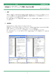
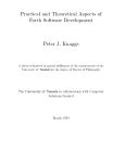
Figure 2.1 illustrates the mapping of the SuperHyway address space to the PCI address spaces. As shown in figure 2.1,
accesses to the PCI area in the SuperHyway address space are mapped to either a PCI address space or a PCI I/O space.
The PI/O transfer control registers (described below) specify the space to which the mapping is to be performed or an
address in a specific space where the mapping is to be performed. Access to a PCI memory space or a PCI I/O space
can be performed by accessing the space (PCI area) on the SuperHyway that is mapped to the PCI space.
A read access to a PCI area generates a read packet for a PCI memory space or PCI I/O space, and a write access to a
PCI area generates a write packet for a PCI memory space or PCI I/O space.
When a PCI memory space is accessed, the packet length is determined according to the access size to the PCI area. In
other words, if the PCI area is accessed by 4-byte access, read/write packets of 4 bytes (1 DW) are generated in the PCI
memory space.
Only 4-byte (1 DW) access to a PCI I/O space is allowed. When a PCI area is mapped to a PCI I/O space, access to the
PCI area should be made with an access size of 4 bytes.
The PIO transfer control registers specify the transfer destination space (selection of PCI memory or I/O space), the
start address in each space, the size of transfer destination space, and the attributes of the transfer packets.
R01AN0557EJ0100 Rev.1.00
Jul 15, 2011
Page 16 of 84
SH7786 Group
SH7786 PCI Express Controller (PCIEC) Initialization Sample Program
Figure 2.1 Mapping of SuperHyway Address Space to PCI Address Spaces
R01AN0557EJ0100 Rev.1.00
Jul 15, 2011
Page 17 of 84
SH7786 Group
(4)
SH7786 PCI Express Controller (PCIEC) Initialization Sample Program
Register Settings for PI/O Transfers
Table 2.6 lists the transfer control registers used for PI/O transfers. Accesses to PCI areas 0 to 3 are mapped to the PCI
memory or I/O spaces according to these register settings. The functions of these registers are listed in table 2.6.
Table 2.6
Transfer Control Registers for PI/O Transfers
PCIEPALR0 to
PCIEPALR3
PCIEPAHR0 to
PCIEPAHR3
PCIEPAMR0 to
PCIEPAMR3
PCIEPTCTLR0 to
PCIEPTCTLR3
Start addresses of the PCI address spaces to which PCI areas 0 to 3 are mapped
(lower 32 bits)
Start addresses of the PCI address spaces to which PCI areas 0 to 3 are mapped
(upper 32 bits)
Specifies the sizes of data in PCI areas 0 to 3 mapped to the PCI address spaces.
Enables/disables PCI areas 0 to 3.
Specifies the transfer destination space (PCI memory space or PCI I/O space).
Specifies attributes (Lock, EP, No Snoop, Relax Ordering) for conversion.
PCIEPALRn and PCIEPAHRn (n = 0 to 3) specify an address in the PCI Express space to which PCI area n is mapped.
PCIEPAMRn specifies the size of the PCI area. It is not possible to specify a size larger than the size of the PCI area as
listed in table 2.5, SuperHyway Space Address Map.
PCIEPTCTLRn specifies whether a given area is enabled or disabled, the transfer destination space, and the attributes
of packets during the transfer process. Unless it is specified in PCIEPTCTLRn that PCI area n is enabled (default:
disabled), any access to the corresponding PCI area is invalid. To perform a lock transfer or specify other attributes,
settings must be made to PCIEPTCTLRn before accessing the PCI area.
R01AN0557EJ0100 Rev.1.00
Jul 15, 2011
Page 18 of 84
SH7786 Group
(5)
SH7786 PCI Express Controller (PCIEC) Initialization Sample Program
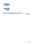
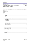
Address Conversion from SuperHyway Bus to PCI
The address used when accessing a PCI space by means of accessing a PCI area is determined by the address of the PCI
area accessed and by the settings of the associated transfer control register. The address conversion details are described
below and illustrated in figure 2.2, Address Conversion to PCI Space. (In the figure and description below, the number
n represents a value of 0 to 3, which corresponds to a PCI areas from 0 to 3).
The lower 16 bits of the PCI address (bits 17 to 2) are generated from the lower bits of the SuperHyway address.
The middle 11 bits of the PCI address (bits 28 to 18) are selected from the corresponding bits of the SuperHyway
address or PCIEPALRn, depending on the value of the transfer control register (PCIEPAMRn). (The SuperHyway
address is used if the value of the corresponding bit in PCIEPAMRn is 1, and PCIEPALRn is used if it is 0.)
The contents of PCIEPAHRn and the upper 3 bits of PCIEPALRn are used as the upper 35 bits (bits 63 to 29) of the
PCI address.
63
32 31 29 28
18 17
0
PCI address
31
0
PCIEPAHRn
31 29 28
18 17
0
PCIEPALRn
0
31 29 28
18 17
0
31 29 28
18 17
0
SuperHyway address
1
Selected for each bit according to the
corresponding bit in PCIEPAMRn.
PCIEPAMRn
Figure 2.2 Address Conversion to PCI Space
R01AN0557EJ0100 Rev.1.00
Jul 15, 2011
Page 19 of 84
SH7786 Group
2.6
SH7786 PCI Express Controller (PCIEC) Initialization Sample Program
Target Transfers (Data Transfer from External Device to PCIEC)
Target transfers are described below. As used here, target transfer refers to the reception of a PCI Express packet from
an external device by the PCIEC and to the transfer of data to another module in the SH7786 via the SuperHyway bus.
(1)
Overview
In a target transfer, an external device accesses the PCIEC by using a PCI Express packet, a request to the SuperHyway
bus is generated, and data is transferred to another module. Target transfers enable an external device to perform
read/write access to another module in the SH7786 or to external memory connected to it, such as DRAM, by
transmitting memory read/write or I/O read/write packets.
In a target transfer, the PCIEC can receive packets of any data length less than or equal to the specified Max Payload
Size (MPS). When a transfer using a size greater than that supported by the SuperHyway bus is specified, the PCIEC
splits the packet and generates multiple internal bus requests.
(2)
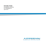
Address Map (PCI Express Space)
Figure 2.3 illustrates mapping of the PCI space to the SuperHyway space.
The assignment of addresses in the PCI Express space is dynamically determined by the root port during the
configuration cycle, based on the register settings at initialization. The register settings at initialization specify the size
and type (memory space or I/O space, etc.) of each area to be allocated. When initialization is completed by setting
CFINIT to 1, the initialization details are reflected in the value of Base Address Register n (BARn) or the R/W
attributes in the configuration registers. Here, n represents the BAR register number: n = 0 to 1 for a root port and n = 0
to 5 for an endpoint.
The root port references these settings during subsequent configuration cycles, determines the address mapping, and
sets the result for each device in BARn in the corresponding configuration register. The address pointed to by BARn
serves as the start address assigned to the individual device in the PCI Express space.
The PCIEC supports either a 64-bit or a 32-bit PCI address space (the first 4G area of the 64-bit space) as the area in
which memory space is allocated. One BARn register is used to allocate an area in a 32-bit address space, and two
contiguous BARn registers (BARn+1/BARn) are used to allocate an area in a 64-bit address space. For this reason, a
maximum of one 64-bit address space area can be allocated for a root port and a maximum of three 64-bit address space
areas for an endpoint.
In I/O spaces, areas are allocated using one BAR register.
Accesses to BARn by the PCI Express are received by the PCIEC, which converts them into accesses to the
SuperHyway bus. The conversion destination address is specified by PCIELARn.
R01AN0557EJ0100 Rev.1.00
Jul 15, 2011
Page 20 of 84
SH7786 Group
SH7786 PCI Express Controller (PCIEC) Initialization Sample Program
PCIEC memory space (64 bits)
H'0000_0000_0000_0000
BAR0
SuperHyway space (32 bits)
H'0000_0000
PCIEC area 0
(memory – 32 bits)
Local area 0
BAR1
PCIEC area 1
(memory – 32 bits)
Local area 1
H'0000_0000_FFFF_FFFF
PCIEC area 3
(memory – 64 bits)
PCIELAR0
PCIELAR1
Local area 3
PCIELAR3
(PCIELAR4 is not used.)
Local area 2
PCIELAR2
H'FFFF_FFFF_FFFF_FFFF
H'FFFF_FFFF
PCIEC I/O space (64 bits)
BAR2
PCIEC area 2 (I/O)
Figure 2.3 Mapping of PCI Spaces to SuperHyway Space
(3)
Register Settings for Target Transfers
Table 2.7 lists the transfer control registers for target transfers. These registers control access to areas allocated in the
PCI spaces and access to the internal bus from the allocated areas.
The PCIEC has six sets of target transfer registers. The PCIEC can allocate a maximum of two PCI areas in a PCI space
when used as a root port and a maximum of six PCI areas in a PCI space when used as an endpoint. The PCIEC
supports allocation of 64-bit or 32-bit spaces as memory space that can be allocated in a PCI space. One set of target
transfer registers allocate one PCI space when a 32-bit space is used, and two sets of transfer registers allocate one PCI
space when a 64-bit space is used.
Table 2.7
Transfer Control Registers for Target Transfers
PCIELARLn
Start address of the local bus (SuperHyway) space to which PCI area n will be mapped
PCIELAMRn
Specifies size of PCI area n.
Note: The value of n is 0 or 1 for a root port and 0 to 5 for an endpoint.
PCIELARLn specifies the address on the SuperHyway bus to which area BARn is mapped. The value of n can be 0 or 1
for a root port and 0 to 5 for an endpoint.
PCIELAMRn specifies the size and type (memory space, I/O space, etc.) of the PCI area allocated in the PCI space, and
whether the area is enabled or disabled. The area cannot be allocated in the PCI space if it is not enabled in
PCIELAMRn, and no transfers will be performed to the internal bus. (The initial setting after a reset is disabled for all
areas.)
R01AN0557EJ0100 Rev.1.00
Jul 15, 2011
Page 21 of 84
SH7786 Group
(4)
SH7786 PCI Express Controller (PCIEC) Initialization Sample Program
Conversion from PCI Address to SuperHyway Bus Address
Figure 2.4 illustrates decoding of PCI space addresses, and figure 2.5 illustrates conversion of PCI addresses to
SuperHyway addresses.
When a PCI Express packet is received, first its address is decoded. The address decoding differs depending on whether
the address width of the received packet is 32 or 64 bits. If the address width is 32 bits, the address in the received
packed is compared with BARn to determine the matching n value. Then the corresponding PCIELARn and
PCIELAMRn are used to convert the address into a SuperHyway bus address. If the address width of the received
packet is 64 bits, the 64-bit address in the received packet is compared the 64-bit address obtained by combining
BARn+1 and BARn to determine the matching n value. Then the corresponding PCIELARn and PCIELAMRn are used
to convert the address into a SuperHyway bus address.
The registers PCIELARn+1 and PCIELAMRn+1 are not used in this process.
The lower bits (bits 17 to 0) of the SuperHyway bus address after conversion are generated from the lower bits of the
received PCI packet. For the middle bits (bits 28 to 18), the corresponding bits of the received packet address or
PCIELARn are used according to the PCIELAMRn bit values. For the upper bits (bits 31 to 29), bits 31 to 29 in
PCIELARn are used without modification.
31
BARn
0
BAR
Bits 31 to n are compared according to
PCIElAMRn (n = 28 to 18).
PCI address
(32 bits)
31
Comparison
0
(a) 32-bit address comparison
BAR
(64 bits)
63
BARn+1
32 31
BARn
0
Bits 31 to n are compared according to
PCIElAMRn (n = 28 to 18).
PCI address
(64 bits)
63
32 31
Comparison
0
(b) 64-bit address comparison
Figure 2.4 PCI Space Address Decoding
Figure 2.5 Conversion from PCI Address to SuperHyway Address
R01AN0557EJ0100 Rev.1.00
Jul 15, 2011
Page 22 of 84
SH7786 Group
(5)
SH7786 PCI Express Controller (PCIEC) Initialization Sample Program
Accessing the SuperHyway Bus from the PCI Express
The internal bus spaces that can be accessed by the PCI Express via the PCIEC are CS2#, CS3#, the DBSC space, and
other PCIEC modules. Here, the other PCIEC modules that can be specified as transfer destinations are PCIEC1 and
PCIEC2 when access is made from PCIEC0, PCIEC0 and PCIEC2 when access is made from PCIEC1, and PCIEC0
and PCIEC1 when access is made from PCIEC2.
2.7
DMA Transfer
DMA transfer using the DMAC incorporated in the PCIEC (PCIEC-DMAC) is described below.
(1)
Overview
The PCIEC-DMAC enables efficient data transfer between the PCI Express and other modules or external memory
devices that are connected via the SuperHyway bus. The PCIEC-DMAC is designed so that it can issue packets with a
maximum data length of 1,024 bytes* to the PCI Express, making possible high-speed data transfers that fully exploit
the high transfer capacity of the PCI Express.
Note: * Max Payload Size defines the maximum length of the packet data issued to the PCI Express.
The PCIEC-DMAC supports stride transfers for the transfer of data from non-contiguous areas and command chains as
a function for executing multiple transfer commands. The stride transfer function enables transfers in which noncontiguous areas serve as the transfer source or destination by adding an offset to the transfer source or destination
address after performing a fixed number of transfers. The command chain function treats a set of DMAC settings, such
as transfer source and destination addresses and transfer sizes, as a command. By providing a function that sequentially
reads and executes commands that are stored in memory, the PCIEC-DMAC supports the continuous execution of
multiple transfers without CPU intervention.
(2)
•
•
•
•
•
•
•
•
•
(3)
Features
Number of channels: 4
Address space: PCI Express = 64 bits, SuperHyway bus = 32 bits
Transfer data length: PCI Express = 4 bytes to 1 KB, SuperHyway bus = 4 to 32 bytes
Maximum transfer count: 536,870,912 (229)
Addressing mode: Dual mode
Transfer requests: Auto-request (started by register control)
Data transfer: Normal mode (continuous transfer), stride transfer, command chain
Priority: Selectable between channel priority fixed mode and round-robin mode
Interrupt requests: Interrupt requests can be issued to the INTC when a data transfer completes or when an error
occurs.
DMAC Transfer Requests
The PCIEC-DMAC supports auto-request mode. The PCIEC-DMAC is activated by writing to its registers by the CPU
or other unit.
R01AN0557EJ0100 Rev.1.00
Jul 15, 2011
Page 23 of 84
SH7786 Group
(4)
SH7786 PCI Express Controller (PCIEC) Initialization Sample Program
Channel Priority
When receiving simultaneous transfer requests with respect to multiple channels, the PCIEC- DMAC performs transfers
according to the specified priority. The priority of channels can be selected from two modes: fixed and round-robin. The
mode is selected by the ABT bit in the PCIEDMAOR register.
To improve transfer efficiency, the PCIEC-DMAC uses the largest possible PCI Express packets for transfer. Once
transmission or reception processing starts, it is not interrupted until transfer processing for the packet is completed. For
this reason, even if a transfer request with a higher priority becomes executable, no channel switching occurs until the
current packet transmission at that stage completes. Channel switching cannot occur until a transfer of up to 4 KB
finishes.
Channel switching occurs when a data transfer set in the active channel completes. Here, transfer set completion means
the point in time when the transfers for both the SuperHyway bus and PCI Express have completed.
(a)
Fixed Mode
In fixed mode, the channel priority does not change. The priority is fixed as follows.
CH0 > CH1 > CH2 > CH3
(b)
Round-Robin Mode
In round-robin mode, when a transfer set has completed in one channel, the channel priority changes so that the
completed channel has the lowest priority.
(5)
Transfer in Normal Mode
In a normal-mode transfer, data is transferred from a specified source address to a specified destination address. Either
of the following transfer directions can be selected: PCI to SuperHyway bus or SuperHyway bus to PCI.
The procedure for performing normal-mode transfers with the PCIEC-DMAC is described below. For detailed
specifications of the individual registers, see 13.4.4, PCIEC-DMAC Control Registers, in SH7786 Group User’s
Manual: Hardware (REJ09B0501).
(a)
General PCIEC-DMAC Settings
Make settings in the PCIEDMAOR register to enable DMA and select the arbitration type.
(b)
Transfer Settings
Specify the PCI and SuperHyway addresses and byte count, and the transfer termination interrupt.
Specify the source and destination addresses in the registers PCIEDMPALRn and PCIEDMPAHRn, PCIEDMSALRn,
and PCIEDMBCNTRn, where n denotes the channel number (0 to 3). Regardless of the direction of transfer, specify the
PCI address in PCIEDMPALRn and PCIEDMPAHRn and the SuperHyway bus address in PCIEDMSALRn.
To generate an interrupt when a transfer is completed, specify an interrupt setting in the PCIEDMCHSRn register.
If the stride transfer function will not be used, clear PCIEDMSBCNTRn and PCIEDMSTRRn to 0.
If the command chain function will not be used, clear PCIEDMCCARn to 0.
(c)
Activating the DMAC
In PCIEDMCHCRn, specify the direction of transfer, and at the same time initiate the transfer process by enabling the
channel.
If the stride transfer function will not be used, clear the SARE bit (bit 24) and PARE bit (bit 25) in PCIEDMCHCRn to
0.
If the command chain function will not be used, clear the CCRE bit (bit 29) in PCIEDMCHCRn to 0.
(d)
Waiting for Transfer End
The end of the transfer can be determined by confirming that the TE bit (bit 0) in PCIEDMCHSRn is set to 1 or by
detecting a transfer end interrupt.
R01AN0557EJ0100 Rev.1.00
Jul 15, 2011
Page 24 of 84
SH7786 Group
(e)
SH7786 PCI Express Controller (PCIEC) Initialization Sample Program
End Processing
Complete the transfer by clearing the CHE bit in (bit 31) in PCIEDMCHCRn to 0. Also, write 1 to the TE bit (bit 0) in
PCIEDMCHSRn to clear it to 0.
The next DMA transfer cannot be started unless end processing is performed.
(6)
Stride Transfer
In a stride transfer, a procedure called “striding” is used in which an offset is added to the source or destination address
after the transfer of a specific number of bytes. By applying striding to the destination address, scatter transfer can be
performed. Similarly, by applying striding to the source address, gather transfer can be performed. By applying striding
to both the source and destination addresses, non-contiguous regions can be transferred.
To use stride transfer, set a stride interval (stride counter) in PCIEDMSBCNTRn and a stride width in PCIEDMSTRRn
when specifying transfer settings. To use stride transfer on the PCI side or SuperHyway side only, set the stride width
(SS or PS field in PCIEDMSTRRn) to 0 for the non-stride transfer side.
To start the DMAC, set the SARE bit (bit 24) or PARE bit (bit 25) in PCIEDMCHCRn to 1.
The other settings are the same as those for normal-mode transfer.
(7)
Command Chain
The command chain function enables the consecutive execution of multiple DMAC commands. Here, DMAC
command refers to a set of information that specifies a PCIEC-DMAC transfer; that is, the information specified in
PCIEDMPALRn, PCIEDMSALRn, PCIEDMBCNTRn, PCIEDMSBCNTRn, PCIEDMSTRRn, PCIEDMCCARn, and
PCIEDMCHCRn. This information can be set in the PCIE-DMAC control registers and also in the memory in the
format shown in figure 2.6. (The upper 32 bits of the address on the PCI side cannot be specified by a DMAC command.
The address specified in the PCIEC-DMAC control registers is always used.) The command chain function enables the
PCIEC-DMAC to read the next DMAC command from memory after execution of a DMAC command, to write the
DMAC command contents to the PCIEC-DMAC control registers, and to execute the DMAC command. By specifying
the next DMAC command in each DMAC command that is read, a DMAC command chain can be built and
consecutive transfers performed.
When a command chain is used, the PCIEC-DMAC first executes the DMAC command specified in the PCIEC-DMAC
control registers for each channel. After execution of this DMAC command, the PCIEC-DMAC reads the next DMAC
command from the address specified in PCIEDMCCARn, writes the command contents to the PCIEC-DMAC control
registers for the corresponding channel, and executes it. If the value of the CCRE bit in the newly read DMAC
command is 1, the PCIEC-DMAC reads the next command again from the memory and executes it after completion of
that command. If the value of the CCRE bit in the read DMAC command is 0, execution of the series of commands in
the chain ends upon completion of that command.
Figure 2.6 PCIEC-DMAC Command Format
R01AN0557EJ0100 Rev.1.00
Jul 15, 2011
Page 25 of 84
SH7786 Group
SH7786 PCI Express Controller (PCIEC) Initialization Sample Program
Command chain execution starts when a channel is enabled while the CCRE bit (bit 29) in PCIEDMCHCRn is set to 1.
Before starting a command chain, it is necessary first to store the chain of DMAC commands in a memory location
accessible from the SuperHyway bus (DDR3-SDRAM, LBSC, IL memory, OL memory, or shared memory specified in
L2CR), and to specify the address of the first command in PCIEDMCCARn.
Each DMAC command stored in memory must satisfy the conditions listed below. The DMAC commands should be
located in a shared memory location such as DDR, LBSC, or LRMA.
• CHE field
This must always be set to 1.
• ATTR field
Set the ATTR field of the DMAC command in memory to the same value as that specified in the ATTR field in the
PCIEC-DMAC control register. The value of the ATTR field cannot be modified by loading a command.
• TC field
Set the traffic class (TC) field of the DMAC command in memory to specify the same virtual channel (VC0) as that
specified by the TC field in the PCIEC-DMAC control register.
• RESERVED field
This must always be set to 8.
• CCA field
The value of the CCA field of the final command executed must be 0.
(8)
PCIE-DMAC Interrupt Sources
The PCIEC-DMAC generates an interrupt for each channel at transfer end as well as an interrupt at error termination on
a common basis for all channels.
R01AN0557EJ0100 Rev.1.00
Jul 15, 2011
Page 26 of 84
SH7786 Group
3.
SH7786 PCI Express Controller (PCIEC) Initialization Sample Program
Serial Communication Interface (SCIF0)
The serial communication interface (SCIF0) incorporates FIFO buffers and supports both asynchronous and clock
synchronous serial communication.
Note that SCIF0 is used as an asynchronous serial console by the sample program.
For a detailed description of SCIF0, see section 24, Serial Communication Interface with FIFO (SCIF), in SH7786
Group User’s Manual: Hardware (REJ09B0501).
4.
Application Example
4.1
AP-SH4AD-0A SH7786 Evaluation Board
The sample program presented in this application note uses two AP-SH4AD-0A SH7786 evaluation boards,
manufactured by Alpha Project, and operates the PCIEC on one of them as a PCI Express root port and the other as a
PCI Express endpoint. For details of the AP-SH4AD-0A, see AP-SH4AD-0A Hardware Manual.
4.1.1
Memory Map
Table 4.1 shows a memory map of the AP-SH4AD-0A.
Table 4.1
AP-SH4AD-0A Memory Map
Area
0
Address
H'0000_0000 to
H'00FF_FFFF
H'0100_0000 to
H'03FF_FFFF
H'0400_0000 to
H'0400_0FFF
H'0400_1000 to
H'07FF_FFFF
H'0800_0000 to
H'0BFF_FFFF
H'0C00_0000 to
H'0FFF_FFFF
H'1000_0000 to
H'13FF_FFFF
H'1400_0000 to
H'17FF_FFFF
1
2
3
4
5
6
H'1800_0000 to
H'1BFF_FFFF
R01AN0557EJ0100 Rev.1.00
Jul 15, 2011
Connected Device
S29GL128P90TFIR20 (16 MB)
Bus Width
16 bits
Shadow
LAN9221 (512 B)
16 bits
Shadow
MT41J64M16LA-187E (256 MB)
32 bits
Left open by user
32 bits
Page 27 of 84
SH7786 Group
4.1.2
SH7786 PCI Express Controller (PCIEC) Initialization Sample Program
Settings for PCI Express Root Port Mode
To set the AP-SH4AD-0A to operate in PCI Express root port mode, set the DIP switches as indicated below. For a
detailed description of the DIP switches, see section 2, Functions, in AP-SH4AD-0A Hardware Manual.
• PCI Express mode setting
SW2-2
MODE11
PCI Express Mode
ON
Root port mode
• PCI Express PHY mode setting
SW2-3
MODE12
PCI Express PHY Mode
ON
4-lane + 1-lane
4.1.3
Settings for PCI Express Endpoint Mode
To set the AP-SH4AD-0A to operate in PCI Express endpoint mode, set the DIP switches as indicated below. For a
detailed description of the DIP switches, see section 2, Functions, in AP-SH4AD-0A Hardware Manual.
• PCI Express mode setting
SW2-2
MODE11
PCI Express Mode
OFF
Endpoint mode
• PCI Express PHY mode setting
SW2-3
MODE12
PCI Express PHY Mode
ON
4-lane + 1-lane
Note: To operate the AP-SH4AD-0A in PCI Express endpoint mode while supplying power from the PCI Express
card edge, use a soldering iron to open solder junction JP1 on the board. For a detailed description of power
supply configuration, see section 3.7.1, Power Supply Examples, in AP-SH4AD-0A Hardware Manual.
4.1.4
Serial Console Settings
The sample program uses SCIF0 as the serial interface of the AP-SH4AD-0A, and the relevant settings are described
below.
The PC-USB-02A is used as the serial console. The PC-USB-02A converts the TTL serial level of SCIF0 into a USB
signal, allowing communication with a PC.
For details of the serial interface and console, see 3.7, Serial Interface, in AP-SH4AD-0A Hardware Manual.
Table 4.2
Item
SCIF0
Baud rate
Data
Parity bit
Stop bit
Flow control
Serial Console Settings
Specification
Asynchronous mode
115,200 bps
8 bits
None
1 bit
None
R01AN0557EJ0100 Rev.1.00
Jul 15, 2011
Page 28 of 84
SH7786 Group
4.2
SH7786 PCI Express Controller (PCIEC) Initialization Sample Program
Description of Sample Program
The sample program presented in this application note uses two AP-SH4AD-0A boards, one operating as a PCI Express
root port and one as a PCI Express endpoint. The description that follows covers the basic method whereby, after initial
PCIEC settings, the PCI Express root port displays on the serial console information from the configuration registers of
the PCI Express endpoint.
4.2.1
System Configuration for Sample Program
Two AP-SH4AD-0A boards, once set as a PCI Express root port and one as a PCI Express endpoint, are connected as
shown below, and the PC-USB-02A serial console is used to display settings (Vendor ID, Device ID, etc.) from the
configuration registers of the PCI Express endpoint on the console PC.
Figure 4.1 System Configuration
R01AN0557EJ0100 Rev.1.00
Jul 15, 2011
Page 29 of 84
SH7786 Group
4.2.2
•
•
•
•
•
•
SH7786 PCI Express Controller (PCIEC) Initialization Sample Program
Specifications of Sample Program
Serial console initial settings
PCIEC initial settings (PCI Express root port mode or PCI Express endpoint mode settings)
Display of PCI Express endpoint Vendor ID and Device ID
Data transfer (transmit/receive) to PCI Express endpoint memory area or IO area
Data transfer (transmit/receive) to PCI Express endpoint memory area by using the on-chip DMA
The following operations are not supported by the sample program.
⎯ Stride transfer and command chain operation by using the on-chip DMA
⎯ Message transmit/receive
⎯ INTx or MSI interrupts
⎯ Link power control function (L0, L0s, L1, and L3 states)
R01AN0557EJ0100 Rev.1.00
Jul 15, 2011
Page 30 of 84
SH7786 Group
4.2.3
(1)
SH7786 PCI Express Controller (PCIEC) Initialization Sample Program
Sample Program Flowcharts
Flowchart of main() Function
This flowchart shows the processing sequence from the start of the main() function, which occurs after initial settings to
LBSC and DBSC3 following a power-on reset.
Start
< main() >
Pin function settings
< pfc_init() >
Make pin function settings.
SCIF0 settings
< scif_init() >
Set SCIF0 to 115,200 bps, 8 bits.
PCIEC ROOT port
or END point ?
PCIEC = Endpoint
( CONFIG_PCIE_END = 1 )
PCIEC = Root port
( CONFIG_PCIE_ROOT = 0 )
Console display (1):
Display “SH7786 PCI Express DEMO Sample root port”.
Console display (1)
No
B
PCIEC (endpoint) initial settings
“Target Device Check? Y/N” appears on the console display, prompting the user
to enter Y to check, or N not to check, the target device.
Check target device?
Console display (2) :
Display “No Check Device”.
Yes
PCI Express initial settings
< pcie_init() >
Make PCIEC (root port) initial settings.
Read PCI Express configuration
space
Read the configuration space of the target
device.
End
Console display (3): Display the Vendor ID and Device ID of the target device.
If the value of VID/DID is 0xFF, display “Device not detected on PCI Bus”.
Console display (3)
Start data transmit?
Console display (2)
No
“Transmit Data Start? Y/N” appears on the console display, prompting the user to enter
Y to transmit/receive data to/from the target device, or N not to transmit/receive data.
Console display (4) :
Display “Transmit Not Start”.
Yes
Console display (4)
A
End
Figure 4.2 Flowchart of main (PCI Express Root Port) (1)
R01AN0557EJ0100 Rev.1.00
Jul 15, 2011
Page 31 of 84
SH7786 Group
SH7786 PCI Express Controller (PCIEC) Initialization Sample Program
A
for( i=0; i<4; i++ )
Write to IO space
< pcie_io_write() >
Write test data to IO space of target device.
Read IO space
< pcie_io_read() >
Read test data from IO space of target device.
Console display (5)
Write to memory space
< pcie_mem_write() >
Read memory space
< pcie_mem_read() >
Console display (6)
Initialize transmit data
Console display (5): Display address and test data read from IO space.
Write test data to memory space of target device.
Read test data from memory space of target device.
Console display (6): Display address and test data read from memory
space.
Load DMA transfer test data (64 bytes) into SDRAM.
Console display (7)
Console display (7): Display “DMA Start WRITE(SuperHyway->PCI)”.
DMA transfer (write) to
memory space
< pcie_start_dma() >
Perform DMA transfer of 64 bytes of test data from SDRAM to memory space
of target device.
Console display (8)
Console display (8): Display “Transfer Data”, transfer source SDRAM address,
and 64 bytes of test data.
Console display (9)
Console display (9): Display “READ(PCI->SuperHyway)”.
DMA transfer (read) from
memory space
< pcie_start_dma() >
Perform DMA transfer of 64 bytes of test data from same memory space of target
device to SDRAM.
Console display (10)
Console display (10): Display “Transfer Data”, transfer destination SDRAM
address, and 64 bytes of test data.
Console display (11)
Console display (11): Display “PCI Express Demo Sample End”.
End
Figure 4.2 Flowchart of main (PCI Express Root Port) (2)
R01AN0557EJ0100 Rev.1.00
Jul 15, 2011
Page 32 of 84
SH7786 Group
SH7786 PCI Express Controller (PCIEC) Initialization Sample Program
B
Console display (1): Display “SH7786 PCI Express DEMO Sample Endpoint”.
Console display (1)
PCI Express initial settings
< pcie_init() >
Make PCIEC (endpoint) initial settings.
Console display (2): Display “PCI Express Demo Sample End”.
Console display (2)
End
Figure 4.3 Flowchart of main (PCI Express Endpoint)
(2)
Flowchart of Pin Function Settings
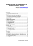
This flowchart shows the processing sequence for making pin function settings.
Figure 4.4 Flowchart of Pin Function Settings
R01AN0557EJ0100 Rev.1.00
Jul 15, 2011
Page 33 of 84
SH7786 Group
(3)
SH7786 PCI Express Controller (PCIEC) Initialization Sample Program
Flowchart of SCIF0 Initial Settings
This flowchart shows the processing sequence for making SCIF0 initial settings for use as a serial console.
Start
< scif_init() >
Set serial control register 0
(SCSCR0)
Clear TIE, RIE, TE, and RE to 0.
Set FIFO control register 0
(SCFCR0)
Clear TX and RX FIFOs.
Set serial status register 0
(SCFSR0)
Clear BRK, DR, and TR to 0.
Set line status register 0
(SCLSR0)
Clear ORER to 0.
EXT: SCK input
Select source clock
Select the source clock to determine the baud rate.
INI: P , EXT: SCK external input
INI: P
Set serial control register 0
(SCSCR0)
Set P as source.
Set bit rate register 0
(SCBRR0)
Set serial control register 0
(SCSCR0)
Set SCK external
input as source clock.
Set to 115,200 bps.
Wait in software
Wait in software for 1 bit period.
Receive FIFO data count trigger: Set to 1.
Transmit FIFO data count trigger: Set to 32.
Set to not clear TX and RX FIFOs.
Transmit enable: Set to 1.
Receive enable: Set to 1.
Set FIFO control register 0
(SCFCR0)
End
Figure 4.5 Flowchart of SCIF0 Initial Settings
R01AN0557EJ0100 Rev.1.00
Jul 15, 2011
Page 34 of 84
SH7786 Group
(4)
SH7786 PCI Express Controller (PCIEC) Initialization Sample Program
Flowchart of PCI Express Bus Initial Settings
This flowchart shows the processing sequence for making PCI Express bus initial settings.
Start
< pcie_init() >
memset
Initialize PCIEC configuration data.
PCIEC software reset
< pcie_soft_reset() >
Perform PCIEC software reset.
Initialize PCI Express
physical layer
< pcie_phy_init() >
Initialize PCI Express physical layer.
Initialize PCI Express
< pcie_trans_cont_init() >
Initialize PCI Express
configuration
Initialize PCI Express (start connection).
Make PCI Express configuration settings.
< pcie_config_init() >
End
Figure 4.6 Flowchart of PCI Express Bus Initial Settings
(5)
Flowchart of PCIEC Software Reset
This flowchart shows the processing sequence for performing a PCIEC software reset.
Start
< pcie_soft_reset() >
Set software reset control register
(PCIESRSTR)
Set transfer control register
(PCIETCTLR)
Execute software reset: Set SRST to 1.
Initialize PCIEC internal registers: Clear CFINIT to 0.
Set software reset control register
(PCIESRSTR)
Cancel software reset: Clear SRST to 0.
Set transmit VCO status register
(PCIETXVC0SR)
Clear VC0 transmit buffer: Set TXBUFCLR to 1.
End
Figure 4.7 Flowchart of PCIEC Software Reset
R01AN0557EJ0100 Rev.1.00
Jul 15, 2011
Page 35 of 84
SH7786 Group
(6)
SH7786 PCI Express Controller (PCIEC) Initialization Sample Program
Flowchart of PCIEC Physical Layer Initialization
This flowchart shows the processing sequence for initializing the PCIEC physical layer.
Start
< pcie_phy_init() >
Console display (1)
Console display (1): Display “PCIe PHY During Initialization...”
Set physical layer control register
(PCIEPHYCTLR)
Initialize physical layer control
register
< phyreg_write() >
Supply physical layer register space access clock: Set PHYCKE to 1.
Initialization sequence
(1) Set physical layer control register address 0x60 to 0x004B_008B.
(2) Set physical layer control register address 0x61 to 0x0000_7B41.
(3) Set physical layer control register address 0x64 to 0x00FF_4F00.
(4) Set physical layer control register address 0x65 to 0x0907_0907.
(5) Set physical layer control register address 0x66 to 0x0000_0010.
(6) Set physical layer control register address 0x74 to 0x0007_001C.
(7) Set physical layer control register address 0x79 to 0x01FC_000D.
(8) Set physical layer control register address 0xB0 to 0x0000_0610.
(9) Set physical layer control register address 0x67 to 0x0000_0400.
PCIEC = Root port
( CONFIG_PCIE_ROOT = 0 )
PCIEC root port
or endpoint ?
PCIEC = Endpoint
( CONFIG_PCIE_END = 1 )
Read physical layer control
register
< phyreg_read() >
Read data from physical layer control register address 0x67.
Set physical layer control register
(PCIEPHYCTLR)
Stop physical layer register space access clock: Clear PHYCKE to 0.
Console display (2)
Console display (2): Display “PCIe PHY During Initialization...Finish”.
End
Figure 4.8 Flowchart of PCIEC Physical Layer Initialization
R01AN0557EJ0100 Rev.1.00
Jul 15, 2011
Page 36 of 84
SH7786 Group
(7)
SH7786 PCI Express Controller (PCIEC) Initialization Sample Program
Flowchart of PCIEC Initialization
This flowchart shows the processing sequence for PCIEC initialization.
Start
< pcie_trans_cont_init() >
Console display (1)
Console display (1): Display “PCIe Controller During Initialization...”
Set local address register 0
(PCIELAR0)
Set local (SuperHyway) address register 0 to 0x0C000000.
Set local address register 2
(PCIELAR2)
Set local (SuperHyway) address register 2 to 0x0D000000.
Set local address mask register 0
(PCIELAMR0)
Set local (SuperHyway) address mask register 0 to 0x000FFF01.
This sets LAMR0 to 1 MB and SPCSEL to secure a 32-bit address
space in memory, and sets LARE to local address enabled.
Set local address mask register 2
(PCIELAMR2)
Set local (SuperHyway) address mask register 2 to 0x000FFF11.
This sets LAMR2 to 1 MB and SPCSEL to secure a 32-bit address
space in I/O, and sets LARE to local address enabled.
Set ID setting register 1
(PCIEIDSETR1)
Set ID setting register 1 (PCIEIDSETR1) to 0x01234567.
Set ID setting register 2
(PCIEIDSETR2)
Set ID setting register 2 (PCIEIDSETR2) to 0x89ABCDEF.
Set PCI configuration register 1
(PCIEPCICONF1)
Set PCI configuration register 1 (PCIEPCICONF1) to 0x00000007.
This enables memory/IO requests, enables memory space access, and
enables IO space access.
Set transfer control register (PCIETCTLR) to 0x00000001.
This activates LTSSM (connection establishment start).
Set transfer control register
(PCIETCTLR)
DLLACT = 0
Data link layer
in active state?
DLLACT = 1 in transfer status register (PCIETSTR)?
DLLACT = 1
Console display (2)
Console display (2): Display “PCIe Controller During Initialization...Finish”.
End
Figure 4.9 Flowchart of PCIEC Initialization
R01AN0557EJ0100 Rev.1.00
Jul 15, 2011
Page 37 of 84
SH7786 Group
(8)
SH7786 PCI Express Controller (PCIEC) Initialization Sample Program
Flowchart of PCI Express Configuration Register Initial Settings
This flowchart shows the processing sequence for making PCI Express configuration register initial settings.
Figure 4.10 Flowchart of PCI Express Configuration Register Initial Settings (1)
R01AN0557EJ0100 Rev.1.00
Jul 15, 2011
Page 38 of 84
SH7786 Group
SH7786 PCI Express Controller (PCIEC) Initialization Sample Program
Figure 4.10 Flowchart of PCI Express Configuration Register Initial Settings (2)
(9)
Flowchart of PCI Express Memory Transfer (Write)
This flowchart shows the processing sequence for performing a PCI Express memory transfer (write).
Figure 4.11 Flowchart of PCI Express Memory Transfer (Write)
R01AN0557EJ0100 Rev.1.00
Jul 15, 2011
Page 39 of 84
SH7786 Group
SH7786 PCI Express Controller (PCIEC) Initialization Sample Program
(10) Flowchart of PCI Express Memory Transfer (Read)
This flowchart shows the processing sequence for performing a PCI Express memory transfer (read).
Figure 4.12 Flowchart of PCI Express Memory Transfer (Read)
(11) Flowchart of PCI Express Memory Transfer Enable Settings
This flowchart shows the processing sequence for making PCI Express memory transfer enable settings.
Start
< pcie_enable_mem_transfer() >
Set PCI address upper register 0
(PCIEPAHR0)
Set PCI address upper register 0 (PCIEPAHR0) to 0x00000000
(32-bit space).
Set PCI address lower register 0
(PCIEPALR0)
Set PCI area 0 address in PCI address lower register 0 (PCIEPALR0)
to 0xFD000000 (32-bit space).
Set PCI address mask register 0
(PCIEPAMR0)
Set PCI address mask register 0 (PCIEPAMR0) to 0x007C0000 to specify
8 MB window size.
Set PCI conversion control
register 0 (PCIEPTCTLR0)
Set PCI conversion control register 0 (PCIEPTCTLR0) to 0x80000000
to specify maximum packet size of 4 bytes, no lock, memory area as
transfer destination, and transmit packet attribute no snoop.
End
Figure 4.13 Flowchart of PCI Express Memory Transfer Enable Settings
R01AN0557EJ0100 Rev.1.00
Jul 15, 2011
Page 40 of 84
SH7786 Group
SH7786 PCI Express Controller (PCIEC) Initialization Sample Program
(12) Flowchart of PCI Express IO Transfer (Write)
This flowchart shows the processing sequence for performing a PCI Express IO transfer (write).
Figure 4.14 Flowchart of PCI Express IO Transfer (Write)
(13) Flowchart of PCI Express IO Transfer (Read)
This flowchart shows the processing sequence for performing a PCI Express IO transfer (read).
Figure 4.15 Flowchart of PCI Express IO Transfer (Read)
R01AN0557EJ0100 Rev.1.00
Jul 15, 2011
Page 41 of 84
SH7786 Group
SH7786 PCI Express Controller (PCIEC) Initialization Sample Program
(14) Flowchart of PCI Express IO Transfer Enable Settings
This flowchart shows the processing sequence for making PCI Express IO transfer enable settings.
Start
< pcie_enable_mem_transfer() >
Set PCI address upper register 3
(PCIEPAHR3)
Set PCI address upper register 3 (PCIEPAHR3) to 0x00000000
(32-bit space).
Set PCI address lower register 3
(PCIEPALR3)
Set PCI area 0 address in PCI address lower register 3 (PCIEPALR3)
to 0xFE100000 (32-bit space).
Set PCI address mask register 3
(PCIEPAMR3)
Set PCI address mask register 3 (PCIEPAMR3) to 0x007C0000 to specify
1 MB window size.
Set PCI conversion control
register 3 (PCIEPTCTLR3)
Set PCI conversion control register 3 (PCIEPTCTLR3) to 0x80000100
to specify maximum packet size of 4 bytes, no lock, IO space as
transfer destination, and transmit packet attribute no snoop.
End
Figure 4.16 Flowchart of PCI Express IO Transfer Enable Settings
R01AN0557EJ0100 Rev.1.00
Jul 15, 2011
Page 42 of 84
SH7786 Group
SH7786 PCI Express Controller (PCIEC) Initialization Sample Program
(15) Flowchart of PCI Express Physical Layer Control Register Write
This flowchart shows the processing sequence for writing to the PCI Express physical layer control register.
Start
< phyreg_write() >
Set physical layer control register
(PCIEPHYCTLR)
Set PHYCKE to 1 to supply clock for accessing physical layer register
space.
Set write data in physical layer
data out register
(PCIEPHYDOUTR)
Set write data in physical layer data out register (PCIEPHYDOUTR).
Write to physical layer address
register (PCIEPHYADRR).
Set write command and address in physical layer address register
(PCIEPHYADRR).
ACK = 0
Determine response form PHY control bus. ACK = 1 indicates access
end.
PHY ACK = 1?
ACK = 1
Write to physical layer address
register (PCIEPHYADRR).
Clear physical layer address register (PCIEPHYADRR).
ACK = 1
PHY ACK = 1?
Determine response form PHY control bus. ACK = 0 indicates idle
state.
ACK = 0
Set physical layer control register
(PCIEPHYCTLR)
Stop clock for accessing physical layer register space by clearing
PHYCKE to 0.
End
Figure 4.17 Flowchart of PCI Express Physical Layer Control Register Write
R01AN0557EJ0100 Rev.1.00
Jul 15, 2011
Page 43 of 84
SH7786 Group
SH7786 PCI Express Controller (PCIEC) Initialization Sample Program
(16) Flowchart of PCI Express Configuration Register Read
This flowchart shows the processing sequence for reading the PCI Express configuration register.
Figure 4.18 Flowchart of PCI Express Configuration Register Read
(17) Flowchart of PCI Express Configuration Register Write
This flowchart shows the processing sequence for writing to the PCI Express configuration register.
Figure 4.19 Flowchart of PCI Express Configuration Register Write
R01AN0557EJ0100 Rev.1.00
Jul 15, 2011
Page 44 of 84
SH7786 Group
SH7786 PCI Express Controller (PCIEC) Initialization Sample Program
(18) Flowchart of PCIEC DMA Transfer
This flowchart shows the processing sequence for performing a PCIEC internal DMAC transfer.
Start
< pcie_start_dma() >
Set PCI DMAC DMA operation
register (PCIEDMAOR)
Set DMA enable bit (DMAE) to 1 in PCI DMAC DMA operation register.
Set PCI DMAC stride count
register 0 (PCIEDMSBCNTR0)
Set PCI DMAC stride count register 0 to 0x00000000.
Set PCI DMAC stride register 0
(PCIEDMSTRR0)
Set PCI DMAC stride register 0 to 0x00000000.
Set PCI DMAC command chain
address register 0
(PCIEDMCCAR0)
Set PCI DMAC command chain address register 0 to 0x00000000.
Set PCI DMAC PCI address lower
register 0 (PCIEDMPALR0)
Set PCI DMAC PCI address lower register 0 to 0xFD000000.
Set PCI DMAC PCI address upper
register 0 (PCIEDMPAHR0)
Set PCI DMAC PCI address upper register 0 to 0xx0000000.
Set PCI DMAC SuperHyway address
lower register 0 (PCIEDMSALR0)
Set SDRAM address in PCI DMAC SuperHyway address lower register 0.
Set PCI DMAC byte count register
0 (PCIEDMBCNTR0)
Ready for DMA transfer?
Set DMA transfer byte count in PCI DMAC byte count register 0.
No
Check PE, SE, and TE flags in PCI DMAC channel status register 0.
Yes
Set PCI DMAC channel control
register 0 (PCIEDMCHCR0)
DMA transfer finished?
Set CHE to 1 in PCI DMAC channel control register 0 to set transfer direction
to DIR.
No
Check TE flag in PCI DMAC channel status register 0.
Yes
Set PCI DMAC channel control
register 0 (PCIEDMCHCR0)
Clear CHE to 0 in PCI DMAC channel control register 0.
Set PCI DMAC channel control
register 0 (PCIEDMCHCR0)
Set TE to 1 in PCI DMAC channel status register 0 to clear the flag.
End
Figure 4.20 Flowchart of PCIEC Internal DMAC Transfer
R01AN0557EJ0100 Rev.1.00
Jul 15, 2011
Page 45 of 84
SH7786 Group
4.2.4
(1)
SH7786 PCI Express Controller (PCIEC) Initialization Sample Program
Sample Program
PCIe_DemoSample.c
This is a program listing of the main function.
001
002
003
004
005
006
007
008
009
010
011
012
013
014
015
016
017
018
019
020
021
022
023
024
025
026
027
028
029
030
031
032
033
034
035
036
037
038
039
040
041
042
043
044
045
046
047
048
049
050
051
052
053
/***********************************************************************/
/*
*/
/* FILE
:PCIe_DemoSample.c
*/
/* DATE
:Wed, Nov 17, 2010
*/
/* DESCRIPTION :Main Program
*/
/* CPU TYPE
:Other
*/
/*
*/
/* This file is generated by Renesas Project Generator (Ver.4.16).
*/
/*
*/
/***********************************************************************/
//#include "typedefine.h"
#include "config.h"
#include "pcie.h"
#ifdef __cplusplus
//#include <ios>
//_SINT ios_base::Init::init_cnt;
#endif
// Remove the comment when you use ios
// Remove the comment when you use ios
void main(void);
#ifdef __cplusplus
extern "C" {
void abort(void);
}
#endif
/* ==== Variable declaration ==== */
//extern static PCIE_CONF_DATA conf_data;
#define BUFF_MAX 7
#define TransByte 64
/* ==== Function declaration ==== */
volatile void BuffClear(char *pBuff, int size);
volatile void SdramDataInit(int cnt);
void pfc_init(void);
/*""FUNC COMMENT""*****************************************************
* ID
:
* Outline
: Sample program main
*
:
* Include
:
* Declaration
: void main(void)
* Description
: Main program
*
:
*
:
*
:
*
:
*
:
R01AN0557EJ0100 Rev.1.00
Jul 15, 2011
Page 46 of 84
SH7786 Group
054
055
056
057
058
059
060
061
062
063
064
065
066
067
068
069
070
071
072
073
074
075
076
077
078
079
080
081
082
083
084
085
086
087
088
089
090
091
092
093
094
095
096
097
098
099
100
101
102
103
104
105
106
107
108
109
110
SH7786 PCI Express Controller (PCIEC) Initialization Sample Program
* Limitation
:
*
:
* Argument
: none
* Return Value
: none
* Calling Functions :
*""FUNC COMMENT END""**************************************************/
void main(void)
{
volatile static int ret = 0;
int i, j;
char KeyBuff[BUFF_MAX];
unsigned long data;
int startadd;
pfc_init();
ret = scif_init();
#ifdef CONFIG_PCIE_ROOT
if( ret == 0 )
printf("\n\r_/_/_/ SH7786 PCI Express DEMO Sample ROOT Port _/_/_/\n\r");
BuffClear( KeyBuff, BUFF_MAX );
// Buffer clear
printf("Target Device Check? Y/N\n\r");
while( scif_recive_data( KeyBuff ) != 0);
switch(KeyBuff[0]) {
case 'Y' :
pcie_init(CONFIG_PCIE_ROOT);
pcie_check(CONFIG_PCIE_ROOT);
break;
case 'N' :
printf("Not Check Device\n\r");
break;
default :
break;
}
delay(1000);
BuffClear( KeyBuff, BUFF_MAX );
// Buffer clear
printf("Transmit Data Start? Y/N\n\r");
while( scif_recive_data( KeyBuff ) != 0);
switch(KeyBuff[0]) {
case 'Y' :
printf("Transmit Start\n\r");
for(i=0;i<4;i++) {
pcie_io_write(CONFIG_PCIE_ROOT, i*4, i+1, Long);
data = pcie_io_read(CONFIG_PCIE_ROOT, i*4, Long);
printf("Addr = %08x, Data = %08x\n\r", 0xFE100000 + (i*4), data);
pcie_mem_write(CONFIG_PCIE_ROOT, i*4, i+2, Long);
data = pcie_mem_read(CONFIG_PCIE_ROOT, i*4, Long);
printf("Addr = %08x, Data = %08x\n\r", 0xFD000000 + (i*4), data);
}
/* DMA Transfer Test */
SdramDataInit(TransByte);
/* 64Byte data set */
printf("\r\nDMA Start ");
printf("\n\rWRTITE(SuperHyway->PCI)\n");
ret = pcie_start_dma(CONFIG_PCIE_ROOT, PCIE_AREA_ADDR, sdram_data_area, PCIE_WRITE, TransByte);
if(!ret) {
printf("\n\rPCIE DMA Error\n");
R01AN0557EJ0100 Rev.1.00
Jul 15, 2011
Page 47 of 84
SH7786 Group
111
112
113
114
115
116
117
118
119
120
121
122
123
124
125
126
127
128
129
130
131
132
133
134
135
136
137
138
139
140
141
142
143
144
145
146
147
148
149
150
151
152
153
154
155
156
157
158
159
160
161
162
163
164
165
166
167
SH7786 PCI Express Controller (PCIEC) Initialization Sample Program
break;
}
startadd = 0xA0000000 | sdram_data_area;
printf("\r\nTransfer Data\n\r");
for(i=0;i<(TransByte/16);i++) {
for(j=0;j<4;j++) {
printf("%08x ", (*(unsigned long *)startadd));
startadd += 4;
}
printf("\n\r");
}
printf("\r\nREAD(PCI->SuperHyway)\n");
ret = pcie_start_dma(CONFIG_PCIE_ROOT, PCIE_AREA_ADDR, sdram_data_area + 0x1000, PCIE_READ, TransByte);
if(!ret) {
printf("\n\rPCIE DMA Error\n");
break;
}
startadd = 0xA0001000 | sdram_data_area;
printf("\r\nTransfer Data\n\r");
for(i=0;i<(TransByte/16);i++) {
for(j=0;j<4;j++) {
printf("%08x ", (*(unsigned long *)startadd));
startadd += 4;
}
printf("\n\r");
}
break;
case 'N' :
printf("Transmit Not Start\n\r");
break;
default :
break;
}
#else
if( ret == 0 )
printf("\n\r_/_/_/ SH7786 PCI Express DEMO Sample END Point _/_/_/\n\r");
pcie_init(CONFIG_PCIE_END);
#endif
printf("PCI Express Demo Sample End\n\r");
}
/*""FUNC COMMENT""*****************************************************
* ID
:
* Outline
: Sample program main
*
: (PCI Express)
* Include
:
* Declaration
: void pfc_init( void )
* Description
: A set of a pin function
*
:
*
:
R01AN0557EJ0100 Rev.1.00
Jul 15, 2011
Page 48 of 84
SH7786 Group
168
169
170
171
172
173
174
175
176
177
178
179
180
181
182
183
184
185
186
187
188
189
190
191
192
193
194
195
196
197
198
199
200
201
202
203
204
205
206
207
208
209
210
211
212
213
214
215
216
217
218
219
220
221
222
223
224
SH7786 PCI Express Controller (PCIEC) Initialization Sample Program
*
:
*
:
*
:
* Limitation
:
*
:
* Argument
: none
* Return Value
: none
* Calling Functions :
*""FUNC COMMENT END""**************************************************/
void pfc_init(void)
{
/* SCIF0 */
GPIOR.PHCR.WORD = 0xFC30;
}
/*""FUNC COMMENT""*****************************************************
* ID
:
* Outline
: Sample program main
*
: (PCI Express)
* Include
:
* Declaration
: void BuffClear(char *pBuff, int size)
* Description
: A initialization of the buffer for serial receive datas
*
:
*
:
*
:
*
:
*
:
* Limitation
:
*
:
* Argument
: *pBuff:Buffer, size:Buffer size
* Return Value
: none
* Calling Functions :
*""FUNC COMMENT END""**************************************************/
volatile void BuffClear(char *pBuff, int size)
{
int i;
for( i = 0; i < size; i++ )
/* A clear of a serial data receiving workpiece*/
{
*( pBuff + i ) = 0;
}
}
/*""FUNC COMMENT""*****************************************************
* ID
:
* Outline
: Sample program main
*
: (PCI Express)
* Include
:
* Declaration
: volatile void SdramDataInit(int cnt)
* Description
: A initialization of the data for sdram
*
:
*
:
*
:
*
:
*
:
* Limitation
:
*
:
* Argument
: none
R01AN0557EJ0100 Rev.1.00
Jul 15, 2011
Page 49 of 84
SH7786 Group
225
226
227
228
229
230
231
232
233
234
235
236
237
238
239
240
241
242
243
244
245
SH7786 PCI Express Controller (PCIEC) Initialization Sample Program
* Return Value
: none
* Calling Functions :
*""FUNC COMMENT END""**************************************************/
volatile void SdramDataInit(int cnt)
{
int i;
int sdram_add = 0xA0000000 | sdram_data_area;
for( i = 0; i < cnt/4; i++ ) /* SDRAM Data Initialize cnt/4 byte */
{
(*(unsigned long *)sdram_add) = i;
sdram_add += 4;
}
}
#ifdef __cplusplus
void abort(void)
{
}
#endif
R01AN0557EJ0100 Rev.1.00
Jul 15, 2011
Page 50 of 84
SH7786 Group
(2)
SH7786 PCI Express Controller (PCIEC) Initialization Sample Program
config.h
This is a header file used by the main function.
01
02
03
04
05
06
07
08
09
10
11
12
13
14
15
16
17
18
19
20
21
22
23
24
25
26
27
28
29
30
31
32
33
34
35
36
37
38
39
40
41
42
43
44
45
46
47
48
49
50
51
#ifndef _CONFIG_H_
#define _CONFIG_H_
#include
#include
#include
#include
<stdarg.h>
<stdio.h>
<stdlib.h>
"iodefine.h"
#defineLong
#defineWord
#defineByte
4
2
1
/* SCIF */
#define
CONFIG_PCLK 44400000
#define
CONFIG_SCIF0
//#define CONFIG_SCIF1
//#define CONFIG_SCIF2
//#define CONFIG_SCIF3
//#define CONFIG_SCIF4
//#define CONFIG_SCIF5
//#define CONFIG_SCIF_CLK_EXTERNAL
#define
CONFIG_SCIF_CLK_PCLK CONFIG_PCLK
#define
CONFIG_BPS 115200
//#define CONFIG_PCIE_ROOT 0
//#define CONFIG_PCIE_END 1
#undef printf
#define printf
scif_printf
/*** SCIF ***/
extern void delay( int cnt );
extern int scif_init(void);
extern char
scif_recive_data( char *Data );
extern char
scif_recive_data_byte( char
*Data );
extern void scif_transmit_data( char *Data );
extern void scif_transmit_data_byte( char *Data );
extern void scif_printf(char* str, ...);
/*** PCIe ***/
extern void pcie_init(int sel);
extern void pcie_check(int sel);
extern void pcie_enable_mem_transfer(int sel);
extern long pcie_mem_write(int sel, unsigned long addr, unsigned long data, unsigned long size);
extern unsigned long pcie_mem_read(int sel, unsigned long addr, unsigned long size);
extern void pcie_enable_io_transfer(int sel);
extern long pcie_io_write(int sel, unsigned long addr, unsigned long data, unsigned long size);
extern unsigned long pcie_io_read(int sel, unsigned long addr, unsigned long size);
#endif /* _CONFIG_H_ */
R01AN0557EJ0100 Rev.1.00
Jul 15, 2011
Page 51 of 84
SH7786 Group
(3)
SH7786 PCI Express Controller (PCIEC) Initialization Sample Program
pcie.c
This is a program listing of the PCIEC initialization function, PCI Express control function, and DMAC control
function.
001
002
003
004
005
006
007
008
009
010
011
012
013
014
015
016
017
018
019
020
021
022
023
024
025
026
027
028
029
030
031
032
033
034
035
036
037
038
039
040
041
042
043
044
045
046
047
048
049
050
051
052
053
/******************************************************************************
* DISCLAIMER
* This software is supplied by Renesas Electronics Corporation. and is only
* intended for use with Renesas products. No other uses are authorized.
* This software is owned by Renesas Electronics Corporation. and is protected under
* all applicable laws, including copyright laws.
*
*
*
*
*
THIS SOFTWARE IS PROVIDED "AS IS" AND RENESAS MAKES NO WARRANTIES
REGARDING THIS SOFTWARE, WHETHER EXPRESS, IMPLIED OR STATUTORY,
INCLUDING BUT NOT LIMITED TO WARRANTIES OF MERCHANTABILITY, FITNESS FOR A
PARTICULAR PURPOSE AND NON-INFRINGEMENT. ALL SUCH WARRANTIES ARE EXPRESSLY
DISCLAIMED.
*
*
*
*
*
TO THE MAXIMUM EXTENT PERMITTED NOT PROHIBITED BY LAW, NEITHER RENESAS
ELECTRONICS CORPORATION. NOR ANY OF ITS AFFILIATED COMPANIES SHALL BE LIABLE
FOR ANY DIRECT, INDIRECT, SPECIAL, INCIDENTAL OR CONSEQUENTIAL DAMAGES
FOR ANY REASON RELATED TO THE THIS SOFTWARE, EVEN IF RENESAS OR ITS
AFFILIATES HAVE BEEN ADVISED OF THE POSSIBILITY OF SUCH DAMAGES.
* Renesas reserves the right, without notice, to make changes to this
* software and to discontinue the availability of this software.
* By using this software, you agree to the additional terms and
* conditions found by accessing the following link:
* http://www.renesas.com/disclaimer
******************************************************************************/
/* Copyright (C) 2010. Renesas Electronics Corporation., All Rights Reserved.*/
/*""FILE COMMENT""*********** Technical reference data ****************
* System Name : SH7786 Sample Program
* File Name
: scif.c
* Abstract
: The example of a set of PCI Express Sample Program
* Version
: Ver 1.00
* Device
: SH7786
* Tool-Chain
: High-performance Embedded Workshop (Version 4.07.00.007)
*
: C/C++ Compiler Package for SuperH Family (V.9.3.2.0)
* OS
: None
* H/W Platform : SH-4A Board P/N:AP-SH4AD-3A (Manufacturer:ALPHA PROJECT)
* Description : It is an example program of the example of a SH7786 PCI Express set.
*
:
* Operation
:
* Limitation
:
*
:
***********************************************************************
* History
: 01.Sep.2010 Ver. 1.00 First Release
*""FILE COMMENT END""**************************************************/
#include "pcie.h"
static PCIE_CONF_DATA conf_data;
/*""FUNC COMMENT""*****************************************************
R01AN0557EJ0100 Rev.1.00
Jul 15, 2011
Page 52 of 84
SH7786 Group
054
055
056
057
058
059
060
061
062
063
064
065
066
067
068
069
070
071
072
073
074
075
076
077
078
079
080
081
082
083
084
085
086
087
088
089
090
091
092
093
094
095
096
097
098
099
100
101
102
103
104
105
106
107
108
109
110
SH7786 PCI Express Controller (PCIEC) Initialization Sample Program
* ID
:
* Outline
: Sample Program Main
*
: (PCI Express)
* Include
:
* Declaration
: void pcie_enable_mem_transfer(int sel)
* Description
: Memory transfer significance
*
:
*
:
*
:
*
:
*
:
* Limitation
:
*
:
* Argument
: none
* Return Value
: none
* Calling Functions :
*""FUNC COMMENT END""**************************************************/
void pcie_enable_mem_transfer(int sel)
{
/* A set of a register (A set of a window) */
PCIE_REG(sel, PAHR0) = 0x00000000;
/* 32bit of a upper address */
PCIE_REG(sel, PALR0) = PCIE_AREA_ADDR; /* 32 bits of a lower address */
PCIE_REG(sel, PAMR0) = 0x007C0000;
/* A window size is specified(8M) */
PCIE_REG(sel, PTCTLR0) = 0x80000000;
/* A transmitting packet property is specified */
}
/*""FUNC COMMENT""*****************************************************
* ID
:
* Outline
: Sample Program Main
*
: (PCI Express)
* Include
:
* Declaration : long pcie_mem_write(int sel, unsigned long addr, unsigned long data, unsigned
* Description
: It writes in a memory space
*
:
*
:
*
:
*
:
*
:
* Limitation
:
*
:
* Argument
: none
* Return Value
: -1:size error, 0:Normal
* Calling Functions :
*""FUNC COMMENT END""**************************************************/
long size)
long pcie_mem_write(int sel, unsigned long addr, unsigned long data, unsigned long size)
{
unsigned long pcie_addr;
/* Memory transfer significance */
pcie_enable_mem_transfer(sel);
/* The write to a memory space */
pcie_addr = PCIE_AREA_ADDR + addr;
switch(size){
case 1:
PCIE_WRITEB(pcie_addr, data);
break;
R01AN0557EJ0100 Rev.1.00
Jul 15, 2011
Page 53 of 84
SH7786 Group
111
112
113
114
115
116
117
118
119
120
121
122
123
124
125
126
127
128
129
130
131
132
133
134
135
136
137
138
139
140
141
142
143
144
145
146
147
148
149
150
151
152
153
154
155
156
157
158
159
160
161
162
163
164
165
166
167
SH7786 PCI Express Controller (PCIEC) Initialization Sample Program
case 2:
PCIE_WRITEW(pcie_addr, data);
break;
case 4:
PCIE_WRITEL(pcie_addr, data);
break;
default:
return -1;
}
return 0;
}
/*""FUNC COMMENT""*****************************************************
* ID
:
* Outline
: Sample Program Main
*
: (PCI Express)
* Include
:
* Declaration : long pcie_endpoint_mem_burst_write(int sel, unsigned long addr, unsigned long *data, unsigned
* Description
: It is a burst write to a memory space
*
:
*
:
*
:
*
:
*
:
* Limitation
:
*
:
* Argument
: none
* Return Value
: -1:size error, 0:Normal
* Calling Functions :
*""FUNC COMMENT END""**************************************************/
long size)
long pcie_mem_burst_write(int sel, unsigned long addr, unsigned long *data, unsigned long size)
{
unsigned long pcie_addr;
int i;
/* Memory transfer is validated */
pcie_enable_mem_transfer(sel);
/* Validation of a packet joining (MAX 4096 byte) */
PCIE_REG(sel, PTCTLR0) = 0x9B000000;
/* The 16byte write to a memory space */
pcie_addr = PCIE_AREA_ADDR + addr;
for(i = 0; i < (size/4); i++) {
PCIE_WRITEL(pcie_addr + i * 4, data[i]);
}
/* A run of a packet joining */
PCIE_REG(sel, PCCTLR) = 0x00000001;
return 0;
}
/*""FUNC COMMENT""*****************************************************
* ID
:
* Outline
: Sample Program Main
R01AN0557EJ0100 Rev.1.00
Jul 15, 2011
Page 54 of 84
SH7786 Group
168
169
170
171
172
173
174
175
176
177
178
179
180
181
182
183
184
185
186
187
188
189
190
191
192
193
194
195
196
197
198
199
200
201
202
203
204
205
206
207
208
209
210
211
212
213
214
215
216
217
218
219
220
221
222
223
224
SH7786 PCI Express Controller (PCIEC) Initialization Sample Program
*
: (PCI Express)
* Include
:
* Declaration
: long pcie_mem_read(unsigned long addr, unsigned long *data, unsigned long size)
* Description
: Read of a memory space
*
:
*
:
*
:
*
:
*
:
* Limitation
:
*
:
* Argument
: none
* Return Value
: -1:size error, 0:Normal
* Calling Functions :
*""FUNC COMMENT END""**************************************************/
unsigned long pcie_mem_read(int sel, unsigned long addr, unsigned long size)
{
unsigned long pcie_addr;
unsigned short wdata;
unsigned char bdata;
unsigned long data;
/* Memory transfer is validated */
pcie_enable_mem_transfer(sel);
/* From a memory space to read */
pcie_addr = PCIE_AREA_ADDR + addr;
switch(size){
case 1:
bdata = PCIE_READB(pcie_addr);
data = (unsigned long) bdata;
break;
case 2:
wdata = PCIE_READW(pcie_addr);
data = (unsigned long) wdata;
break;
case 4:
data = PCIE_READL(pcie_addr);
break;
default:
data = 0;
break;;
}
return data;
}
/*""FUNC COMMENT""*****************************************************
* ID
:
* Outline
: Sample Program Main
*
: (PCI Express)
* Include
:
* Declaration
: void pcie_enable_io_transfer(int sel)
* Description
: An I/O transmission is validated
*
:
*
:
*
:
R01AN0557EJ0100 Rev.1.00
Jul 15, 2011
Page 55 of 84
SH7786 Group
225
226
227
228
229
230
231
232
233
234
235
236
237
238
239
240
241
242
243
244
245
246
247
248
249
250
251
252
253
254
255
256
257
258
259
260
261
262
263
264
265
266
267
268
269
270
271
272
273
274
275
276
277
278
279
280
281
SH7786 PCI Express Controller (PCIEC) Initialization Sample Program
*
:
*
:
* Limitation
:
*
:
* Argument
: none
* Return Value
: none
* Calling Functions :
*""FUNC COMMENT END""**************************************************/
void pcie_enable_io_transfer(int sel)
{
/* A set of a register (A set of a window) */
PCIE_REG(sel, PAHR3) = 0x00000000;
/* 32 bits of a upper address */
PCIE_REG(sel, PALR3) = PCIE_AREA_IO_ADDR;
/* 32 bits of a lower address */
PCIE_REG(sel, PAMR3) = 0x000C0000;
/* A window size is specified(1M) */
PCIE_REG(sel, PTCTLR3) = 0x80000100;
/* A transmitting packet property is specified */
}
/*""FUNC COMMENT""*****************************************************
* ID
:
* Outline
: Sample Program Main
*
: (PCI Express)
* Include
:
* Declaration
: long pcie_io_write(unsigned long addr, unsigned long data, unsigned long size)
* Description
: It writes in an I/O field
*
:
*
:
*
:
*
:
*
:
* Limitation
:
*
:
* Argument
: none
* Return Value
: -1:size error, 0:Normal
* Calling Functions :
*""FUNC COMMENT END""**************************************************/
long pcie_io_write(int sel, unsigned long addr, unsigned long data, unsigned long size)
{
unsigned long pcie_addr;
/* Validation of an I/O transmission */
pcie_enable_io_transfer(sel);
/* The write to an I/O field */
pcie_addr = PCIE_AREA_IO_ADDR + addr;
switch(size){
case 1:
PCIE_WRITEB(pcie_addr, data);
break;
case 2:
PCIE_WRITEW(pcie_addr, data);
break;
case 4:
PCIE_WRITEL(pcie_addr, data);
break;
default:
return -1;
}
R01AN0557EJ0100 Rev.1.00
Jul 15, 2011
Page 56 of 84
SH7786 Group
282
283
284
285
286
287
288
289
290
291
292
293
294
295
296
297
298
299
300
301
302
303
304
305
306
307
308
309
310
311
312
313
314
315
316
317
318
319
320
321
322
323
324
325
326
327
328
329
330
331
332
333
334
335
336
337
338
SH7786 PCI Express Controller (PCIEC) Initialization Sample Program
return 0;
}
/*""FUNC COMMENT""*****************************************************
* ID
:
* Outline
: Sample Program Main
*
: (PCI Express)
* Include
:
* Declaration
: long pcie_io_read(int sel, unsigned long addr, unsigned long *data, unsigned long
* Description
: Read of an input-output field
*
:
*
:
*
:
*
:
*
:
* Limitation
:
*
:
* Argument
: none
* Return Value
: -1:size error, 0:Normal
* Calling Functions :
*""FUNC COMMENT END""**************************************************/
unsigned long pcie_io_read(int sel, unsigned long addr, unsigned long size)
{
unsigned long pcie_addr;
unsigned short wdata;
unsigned char bdata;
unsigned long data;
size)
/* Validation of an I/O transmission */
pcie_enable_io_transfer(sel);
/* From an I/O field to read */
pcie_addr = PCIE_AREA_IO_ADDR + addr;
switch(size){
case 1:
bdata = PCIE_READB(pcie_addr);
data = (unsigned long) bdata;
break;
case 2:
wdata = PCIE_READW(pcie_addr);
data = (unsigned long) wdata;
break;
case 4:
data = PCIE_READL(pcie_addr);
break;
default:
data = 0;
break;
}
return data;
}
/*""FUNC COMMENT""*****************************************************
R01AN0557EJ0100 Rev.1.00
Jul 15, 2011
Page 57 of 84
SH7786 Group
339
340
341
342
343
344
345
346
347
348
349
350
351
352
353
354
355
356
357
358
359
360
361
362
363
364
365
366
367
368
369
370
371
372
373
374
375
376
377
378
379
380
381
382
383
384
385
386
387
388
389
390
391
392
393
394
395
SH7786 PCI Express Controller (PCIEC) Initialization Sample Program
* ID
:
* Outline
: Sample Program Main
*
: (PCI Express)
* Include
:
* Declaration
: static int phyreg_write(int sel, int addr, int lane, unsigned long data)
* Description
: The write to a physical-layer control register
*
:
*
:
*
:
*
:
*
:
* Limitation
:
*
:
* Argument
: none
* Return Value
: 0
* Calling Functions :
*""FUNC COMMENT END""**************************************************/
static int phyreg_write(int sel, int addr, int lane, unsigned long data)
{
unsigned long wdata;
/*The write to a physical-layer control register */
wdata = 0x00010000 + ((lane & 0xf) << 8) + (addr & 0xff);
PCIE_REG(sel, PHYCTLR) = 0x00000001; /* clock enable */
PCIE_REG(sel, PHYDOUTR) = data;
/* A set of a writed data */
PCIE_REG(sel, PHYADRR) = wdata;
/* A set of a command/address */
while( (PCIE_REG(sel, PHYADRR) & 0x01000000) == 0 );
/* Waiting for ACK */
PCIE_REG(sel, PHYADRR) = 0x00000000; /* Command clear */
while( (PCIE_REG(sel, PHYADRR) & 0x01000000) != 0 );
PCIE_REG(sel, PHYCTLR) = 0x00000000; /* Clock disabling */
return 0;
}
/*""FUNC COMMENT""*****************************************************
* ID
:
* Outline
: Sample Program Main
*
: (PCI Express)
* Include
:
* Declaration
: static int phyreg_read(int sel, int addr, int lane, unsigned long *data)
* Description
: Read of a physical-layer control register
*
:
*
:
*
:
*
:
*
:
* Limitation
:
*
:
* Argument
: none
* Return Value
: 0
* Calling Functions :
*""FUNC COMMENT END""**************************************************/
static int phyreg_read(int sel, int addr, int lane, unsigned long *data)
{
R01AN0557EJ0100 Rev.1.00
Jul 15, 2011
Page 58 of 84
SH7786 Group
396
397
398
399
400
401
402
403
404
405
406
407
408
409
410
411
412
413
414
415
416
417
418
419
420
421
422
423
424
425
426
427
428
429
430
431
432
433
434
435
436
437
438
439
440
441
442
443
444
445
446
447
448
449
450
451
452
SH7786 PCI Express Controller (PCIEC) Initialization Sample Program
unsigned long wdata;
/*Read of a physical-layer control register */
wdata = 0x00020000 + ((lane & 0xf) << 8) + (addr & 0xff);
PCIE_REG(sel, PHYCTLR) = 0x00000001; /* clock enable */
PCIE_REG(sel, PHYADRR) = wdata;
/* A set of a command/address */
while( (PCIE_REG(sel, PHYADRR) & 0x01000000) == 0 );
/* Waiting for ACK */
*data = PCIE_REG(sel, PHYDINR);
/* Read data */
PCIE_REG(sel, PHYADRR) = 0x00000000; /* Command clear */
while( (PCIE_REG(sel, PHYADRR) & 0x01000000) != 0 );
PCIE_REG(sel, PHYCTLR) = 0x00000000; /* Clock disabling */
return 0;
}
/*""FUNC COMMENT""*****************************************************
* ID
:
* Outline
: Sample Program Main
*
: (PCI Express)
* Include
:
* Declaration: static int config_read(int sel, int bus, int dev, int func, int regno, unsigned
* Description
: Read of a configuration register
*
:
*
:
*
:
*
:
*
:
* Limitation
:
*
:
* Argument
: none
* Return Value
: 0
* Calling Functions :
*""FUNC COMMENT END""**************************************************/
long *data)
static int config_read(int sel, int bus, int dev, int func, int regno, unsigned long *data)
{
unsigned long wdata;
PCIE_REG(sel, PCTLR) = 0x80000000; /* An issue Clearance of a configuration request */
wdata = (bus << 24) + (dev << 19) + (func << 16) + regno;
PCIE_REG(sel, PAR) = wdata;
/* Set of addr, bus/dev/func */
*data = PCIE_REG(sel, PDR);
/* Issue of configuration read */
PCIE_REG(sel, PCTLR) = 0x00000000; /* Issue of a configuration request is forbidden */
return 0;
}
/*""FUNC COMMENT""*****************************************************
* ID
:
* Outline
: Sample Program Main
*
: (PCI Express)
* Include
:
* Declaration: static int config_write(int sel, int bus, int dev, int func, int regno, unsigned
R01AN0557EJ0100 Rev.1.00
Jul 15, 2011
long data)
Page 59 of 84
SH7786 Group
453
454
455
456
457
458
459
460
461
462
463
464
465
466
467
468
469
470
471
472
473
474
475
476
477
478
479
480
481
482
483
484
485
486
487
488
489
490
491
492
493
494
495
496
497
498
499
500
501
502
503
504
505
506
507
508
509
SH7786 PCI Express Controller (PCIEC) Initialization Sample Program
* Description
: Write of a configuration register
*
:
*
:
*
:
*
:
*
:
* Limitation
:
*
:
* Argument
: none
* Return Value
: 0
* Calling Functions :
*""FUNC COMMENT END""**************************************************/
static int config_write(int sel, int bus, int dev, int func, int regno, unsigned long data)
{
unsigned long wdata;
PCIE_REG(sel, PCTLR) = 0x80000000;
/* An issue Clearance of a configuration request */
wdata = (bus << 24) + (dev << 19) + (func << 16) + regno;
PCIE_REG(sel, PAR) = wdata;
/* Set of addr, bus/dev/func */
PCIE_REG(sel, PDR) = data;
/* Issue of configuration read */
PCIE_REG(sel, PCTLR) = 0x00000000;
/* Issue of a configuration request is forbidden */
return 0;
}
/*""FUNC COMMENT""*****************************************************
* ID
:
* Outline
: Sample Program Main
*
: (PCI Express)
* Include
:
* Declaration
: static void pcie_soft_reset(int sel)
* Description
: Software reset of a PCIE controller
*
:
*
:
*
:
*
:
*
:
* Limitation
:
*
:
* Argument
: none
* Return Value
: none
* Calling Functions :
*""FUNC COMMENT END""**************************************************/
static void pcie_soft_reset(int sel)
{
/* A run of software reset */
PCIE_REG(sel, SRSTR) = 0x00000001;
/* A reset of a PCIE internal register */
PCIE_REG(sel, TCTLR) = 0x00000000;
/* A reset of software reset */
PCIE_REG(sel, SRSTR) = 0x00000000;
/* A clear of a VCO transmitter buffer */
R01AN0557EJ0100 Rev.1.00
Jul 15, 2011
Page 60 of 84
SH7786 Group
510
511
512
513
514
515
516
517
518
519
520
521
522
523
524
525
526
527
528
529
530
531
532
533
534
535
536
537
538
539
540
541
542
543
544
545
546
547
548
549
550
551
552
553
554
555
556
557
558
559
560
561
562
563
564
565
566
SH7786 PCI Express Controller (PCIEC) Initialization Sample Program
PCIE_REG(sel, TXVC0SR) = 0x80000000;
}
/*""FUNC COMMENT""*****************************************************
* ID
:
* Outline
: Sample Program Main
*
: (PCI Express)
* Include
:
* Declaration
: static int pcie_phy_init(int sel)
* Description
: The initialization of a PCIE controller transfer control register
*
:
*
:
*
:
*
:
*
:
* Limitation
:
*
:
* Argument
: none
* Return Value
: -1:Time out, 0:Normal
* Calling Functions :
*""FUNC COMMENT END""**************************************************/
static int pcie_phy_init(int sel)
{
unsigned long stime;
static unsigned long data;
printf("PCI Express PHY During Initialization...");
/* A clock supply of a physical-layer register space accessing */
PCIE_REG(sel, PHYCTLR) = 0x00000001;
/* A physical layer's initialization */
phyreg_write(sel, 0x60, 0xf, 0x004B008B);
phyreg_write(sel, 0x61, 0xf, 0x00007B41);
phyreg_write(sel, 0x64, 0xf, 0x00FF4F00);
phyreg_write(sel, 0x65, 0xf, 0x09070907);
phyreg_write(sel, 0x66, 0xf, 0x00000010);
phyreg_write(sel, 0x74, 0xf, 0x0007001C);
phyreg_write(sel, 0x79, 0xf, 0x01FC000D);
phyreg_write(sel, 0xB0, 0xf, 0x00000610);
/* A boot of a physical layer */
phyreg_write(sel, 0x67, 0x1, 0x00000400);
if(sel)
phyreg_read(sel, 0x67, 0x1, &data);
/*The clock of a physical-layer register space accessing is suspended */
PCIE_REG(sel, PHYCTLR) = 0x00000000;
/* Waiting for set a physical module */
stime = 1000;
while(stime--) {
/* It waits until a physical module will be in a ready state */
if( (PCIE_REG(sel, PHYSR) & 0x00000001) != 0 ) {
break;
}
delay(1000);
R01AN0557EJ0100 Rev.1.00
Jul 15, 2011
Page 61 of 84
SH7786 Group
567
568
569
570
571
572
573
574
575
576
577
578
579
580
581
582
583
584
585
586
587
588
589
590
591
592
593
594
595
596
597
598
599
600
601
602
603
604
605
606
607
608
609
610
611
612
613
614
615
616
617
618
619
620
621
622
623
SH7786 PCI Express Controller (PCIEC) Initialization Sample Program
}
if(!stime)
return -1;
printf("
Finish\n\r");
return 0;
}
/*""FUNC COMMENT""*****************************************************
* ID
:
* Outline
: Sample Program Main
*
: (PCI Express)
* Include
:
* Declaration
: static int pcie_trans_cont_init(int sel)
* Description
: The initialization of a PCIE controller transfer control register
*
:
*
:
*
:
*
:
*
:
* Limitation
:
*
:
* Argument
: none
* Return Value
: -1:Time out, 0:Normal
* Calling Functions :
*""FUNC COMMENT END""**************************************************/
static int pcie_trans_cont_init(int sel)
{
unsigned long stime;
printf("PCI Express Controller During Initialization...");
/* A set of a bridge facility */
PCIE_REG(sel, LAR0) = 0x0C000000; /* A local address 0 is specified */
PCIE_REG(sel, LAR2) = 0x0D000000;
/* A local address 1 is specified */
PCIE_REG(sel, LAMR0) = 0x000FFF01;
/* Local(SHwy)space register 0 */
/* 1MB */
/* A memory is secured in 32 bit address space */
/* Local address enabling is specified */
PCIE_REG(sel, LAMR2) = 0x000FFF11;
/* Local(SHwy)space register 1 */
/* 1MB */
/* A memory is secured in 32 bit address space */
/* Local address enabling is specified */
/* A set of a configuration register */
if(sel) {
PCIE_REG(sel, IDSETR1) = 0x01234567;
PCIE_REG(sel, IDSETR2) = 0x89ABCDEF;
}
PCIE_REG(sel, PCICONF1) = 0x00000007;
/* A wake-up of LTSSM(A settlement of a connection is started) */
PCIE_REG(sel, TCTLR) = 0x00000001;
R01AN0557EJ0100 Rev.1.00
Jul 15, 2011
Page 62 of 84
SH7786 Group
624
625
626
627
628
629
630
631
632
633
634
635
636
637
638
639
640
641
642
643
644
645
646
647
648
649
650
651
652
653
654
655
656
657
658
659
660
661
662
663
664
665
666
667
668
669
670
671
672
673
674
675
676
677
678
679
680
SH7786 PCI Express Controller (PCIEC) Initialization Sample Program
/* A connection's settlement waiting */
stime = 10000;
while(stime--) {
/* Data Link Layer Active check */
if(PCIE_REG(sel, TSTR) != 0) {
break;
}
delay(1000);
}
if(!stime)
return -1;
printf("
Finish\n\r");
return 0;
}
/*""FUNC COMMENT""*****************************************************
* ID
:
* Outline
: Sample Program Main
*
: (PCI Express)
* Include
:
* Declaration
: static int pcie_config_init(void)
* Description
: A set of the configuration of a PCIE controller
*
:
*
:
*
:
*
:
*
:
* Limitation
:
*
:
* Argument
: none
* Return Value
: -1:Inaccurate ID, 0:Normal
* Calling Functions :
*""FUNC COMMENT END""**************************************************/
static int pcie_config_init(int sel)
{
unsigned long config_data[(PCIE_MAX_CONFREG_SIZE/4)];
unsigned long regno;
unsigned long data;
unsigned long dev_id;
unsigned long dev_cap;
unsigned long dev_ctrl;
unsigned long dev_bar;
unsigned long dev_type;
unsigned char cap_ptr, next_ptr, cap_id, mpss1, mpss2, mps;
int stime = 1000;
/* A confirm of a vender and product ID */
while(stime--) {
config_read(sel, 0, 1, 0, PCIE_CONF_DEVICE_ID, &data);
if(!(PCIE_REG(sel, PCTLR) & 0x00010000))
break;
delay(1000);
}
if(!stime)
return -1;
dev_id = data;
R01AN0557EJ0100 Rev.1.00
Jul 15, 2011
Page 63 of 84
SH7786 Group
681
682
683
684
685
686
687
688
689
690
691
692
693
694
695
696
697
698
699
700
701
702
703
704
705
706
707
708
709
710
711
712
713
714
715
716
717
718
719
720
721
722
723
724
725
726
727
728
729
730
731
732
733
734
735
736
737
SH7786 PCI Express Controller (PCIEC) Initialization Sample Program
if(dev_id == 0x00000000) {
return -1;
}
/* Max Payload Size Supported of a splicing place device is acquired. */
config_read(sel, 0, 1, 0, PCIE_CONF_CAP_PTR, &data);
next_ptr = data & 0xff;
cap_id = 0xff;
while(1) {
if (cap_id == 0x10) {
/* PCI Express Capability Structure */
config_read(sel, 0, 1, 0, (unsigned long)(cap_ptr+0x04), &dev_cap);
mpss1 = dev_cap & 0x07;
break;
} else {
/* other capability list */
cap_ptr = next_ptr;
config_read(sel, 0, 1, 0, (unsigned long)cap_ptr, &data);
cap_id = data & 0xff;
next_ptr = (data >> 8) & 0xff;
}
}
/* MPSS of a self-device */
mpss2 = PCIE_REG(sel, EXPCAP1) & 0x07;
mps = (mpss1 < mpss2) ? mpss1 : mpss2; /* Both smallest value is taken. */
/* Set of MPS : Splicing place device */
config_read(sel, 0,1,0,(unsigned long)(cap_ptr + 0x08), &dev_ctrl);
dev_ctrl = (dev_ctrl & 0xFFFFFF1F) | (mps << 5); /* bit7-5 is substituted for MPS */
config_write(sel, 0,1,0,(unsigned long)(cap_ptr + 0x08), dev_ctrl);
/* Set of MPS: self-device */
dev_ctrl = PCIE_REG(sel, EXPCAP2);
dev_ctrl = (dev_ctrl & 0xFFFFFF1F) | (mps << 5); /* bit7-5 is substituted for MPS */
PCIE_REG(sel, EXPCAP1) = dev_ctrl;
/* A set of a command and a register */
config_write(sel, 0, 1, 0, PCIE_CONF_COMMAND, 0x00000007);
/* External device */
/* Set of BAR: Splicing place device */
config_read(sel, 0, 1, 0, PCIE_CONF_BASE_ADDRESS_0, &dev_bar);
dev_type = dev_bar & 0x06;
if(dev_type == 0x00) {
/* 32 bit space */
config_write(sel, 0, 1, 0, PCIE_CONF_BASE_ADDRESS_0, PCIE_AREA_ADDR);
config_write(sel, 0, 1, 0, PCIE_CONF_BASE_ADDRESS_2, PCIE_AREA_IO_ADDR);
} else if(dev_type == 0x04) {
/* 64 bit space */
config_write(sel, 0, 1, 0, PCIE_CONF_BASE_ADDRESS_0, PCIE_AREA_ADDR);
config_write(sel, 0, 1, 0, PCIE_CONF_BASE_ADDRESS_1, 0x00000000);
}
/* An obtaining of all the configuration registers of an external device */
for (regno = 0; regno < (PCIE_MAX_CONFREG_SIZE/4); regno++) {
config_read(sel, 0, 1, 0, regno * 4, &data);
config_data[regno] = data;
R01AN0557EJ0100 Rev.1.00
Jul 15, 2011
Page 64 of 84
SH7786 Group
738
739
740
741
742
743
744
745
746
747
748
749
750
751
752
753
754
755
756
757
758
759
760
761
762
763
764
765
766
767
768
769
770
771
772
773
774
775
776
777
778
779
780
781
782
783
784
785
786
787
788
789
790
791
792
793
794
SH7786 PCI Express Controller (PCIEC) Initialization Sample Program
}
memcpy( &conf_data, config_data, sizeof( PCIE_CONF_DATA ) );
return 0;
}
/*""FUNC COMMENT""*****************************************************
* ID
:
* Outline
: Sample Program Main
*
: (PCI Express)
* Include
:
* Declaration
: static unsigned long pcie_link_lane(void)
* Description
: An obtaining of an effective lane
*
:
*
:
*
:
*
:
*
:
* Limitation
:
*
:
* Argument
: none
* Return Value
: An obtaining of a link data
* Calling Functions :
*""FUNC COMMENT END""**************************************************/
static unsigned long pcie_link_lane(int sel)
{
unsigned long data;
/* The read of a link status */
data = PCIE_REG(sel, EXPCAP4);
data >>= 20;
data &= 0x3f;
return data;
}
/*""FUNC COMMENT""*****************************************************
* ID
:
* Outline
: Sample Program Main
*
: (PCI Express)
* Include
:
* Declaration
: void pcie_init(int sel)
* Description
: The initialization of a PCIE controller
*
:
*
:
*
:
*
:
*
:
* Limitation
:
*
:
* Argument
: none
* Return Value
: none
* Calling Functions :
*""FUNC COMMENT END""**************************************************/
void pcie_init(int sel)
{
/* The initialization of a PCIE configuration data */
R01AN0557EJ0100 Rev.1.00
Jul 15, 2011
Page 65 of 84
SH7786 Group
795
796
797
798
799
800
801
802
803
804
805
806
807
808
809
810
811
812
813
814
815
816
817
818
819
820
821
822
823
824
825
826
827
828
829
830
831
832
833
834
835
836
837
838
839
840
841
842
843
844
845
846
847
848
849
850
851
SH7786 PCI Express Controller (PCIEC) Initialization Sample Program
memset( &conf_data, 0xFF, sizeof( PCIE_CONF_DATA ) );
/* Software reset */
pcie_soft_reset(sel);
/* A physical layer's initialization */
if( pcie_phy_init(sel) < 0 ) {
return;
}
/* The initialization of PCIE (A connection start) */
if( pcie_trans_cont_init(sel) < 0 ) {
return;
}
/* A set of a configuration */
if( pcie_config_init(sel) < 0 ) {
return;
}
}
/*""FUNC COMMENT""*****************************************************
* ID
:
* Outline
: Sample Program Main
*
: (PCI Express)
* Include
:
* Declaration
: void pcie_check(int sel)
* Description
: The check of a PCIE controller device
*
:
*
:
*
:
*
:
*
:
* Limitation
:
*
:
* Argument
: none
* Return Value
: none
* Calling Functions :
*""FUNC COMMENT END""**************************************************/
void pcie_check(int sel)
{
unsigned long lane;
/* A view of a configuration register */
if( (conf_data.VenderID != 0xFFFF) && (conf_data.DeviceID != 0xFFFF) ) {
scif_printf(" Enable lane : %d LANE\n\r", pcie_link_lane(sel));
scif_printf("\n\r");
scif_printf("
scif_printf("
scif_printf("
scif_printf("
scif_printf("
Vender ID
Device ID
Command
Status
Revision ID
:
:
:
:
:
%04x\n\r",
%04x\n\r",
%04x\n\r",
%04x\n\r",
%02x\n\r",
conf_data.VenderID);
conf_data.DeviceID);
conf_data.Command );
conf_data.Status );
conf_data.RevisionID);
scif_printf(" ProgrammingInterface : %02x\n\r", conf_data.ProgrammingInterface);
scif_printf(" SubClass
scif_printf(" BaseClass
R01AN0557EJ0100 Rev.1.00
Jul 15, 2011
: %02x\n\r", conf_data.SubClass);
: %02x\n\r", conf_data.BaseClass);
Page 66 of 84
SH7786 Group
852
853
854
855
856
857
858
859
860
861
862
863
864
865
866
867
868
869
870
871
872
873
874
875
876
877
878
879
880
881
882
883
884
885
886
887
888
889
890
891
892
893
894
895
896
897
898
899
900
901
902
903
904
905
906
907
908
SH7786 PCI Express Controller (PCIEC) Initialization Sample Program
scif_printf("
scif_printf("
scif_printf("
scif_printf("
scif_printf("
scif_printf("
scif_printf("
scif_printf("
scif_printf("
scif_printf("
scif_printf("
scif_printf("
scif_printf("
CachLineSize: %02x\n\r", conf_data.CachLineSize);
LatencyTimer: %02x\n\r", conf_data.LatencyTimer);
HeaderType : %02x\n\r", conf_data.HeaderType);
BIST
: %02x\n\r", conf_data.BIST);
BaseAdrsREG : %08x\n\r", conf_data.BaseAddressRegisters[0]);
BaseAdrsREG : %08x\n\r", conf_data.BaseAddressRegisters[1]);
BaseAdrsREG : %08x\n\r", conf_data.BaseAddressRegisters[2]);
BaseAdrsREG : %08x\n\r", conf_data.BaseAddressRegisters[3]);
BaseAdrsREG : %08x\n\r", conf_data.BaseAddressRegisters[4]);
BaseAdrsREG : %08x\n\r", conf_data.BaseAddressRegisters[5]);
CardbusCISpointer : %08x\n\r", conf_data.CardbusCISpointer);
SubsystemVenderID : %04x\n\r", conf_data.SubsystemVenderID);
SubsystemID : %04x\n\r", conf_data.SubsystemID);
scif_printf(" ExpantionROMbaseAddress : %08x\n\r", conf_data.ExpantionROMbaseAddress);
scif_printf(" CAP_PTR
: %02x\n\r", conf_data.CAP_PTR);
scif_printf(" Int Line
: %02x\n\r", conf_data.InttreuptLine);
scif_printf(" Int Pin
: %02x\n\r", conf_data.InttreuptPin);
scif_printf(" Min_Gnt
: %02x\n\r", conf_data.Min_Gnt);
scif_printf(" Max_Lat
: %02x\n\r", conf_data.Max_Lat);
} else {
/* no device */
scif_printf("Device not detected on PCI Bus!\r\n");
}
}
/*""FUNC COMMENT""*****************************************************
* ID
:
* Outline
: Sample Program Main
*
: (PCI Express)
* Include
:
* Declaration
: int pcie_start_dma(int sel, int pciadd, int shadd, int dir, int cnt)
* Description
: PCIEC-DMAC Setting and start
*
:
*
:
*
:
*
:
*
:
* Limitation
:
*
:
* Argument
: none
* Return Value
: none
* Calling Functions :
*""FUNC COMMENT END""**************************************************/
int pcie_start_dma(int sel, int pciadd, int shadd, int dir, int cnt)
{
int stime, status;
/* DMA Nomal Transfer */
PCIE_REG(sel, DMAOR) = DMAE;
/* DMAC Enable */
PCIE_REG(sel, DMSBCNTR0) = 0x00000000;
PCIE_REG(sel, DMSTRR0) = 0x00000000;
PCIE_REG(sel, DMCCAR0) = 0x00000000;
/* No Stride Transfer */
PCIE_REG(sel, DMPALR0) = pciadd;
PCIE_REG(sel, DMPAHR0) = 0x00000000;
/* 32bit of a lower address for PCI */
/* 32bit of a upper address for PCI */
PCIE_REG(sel, DMSALR0) = shadd;
/* 32bit of a address for SuperHyway */
R01AN0557EJ0100 Rev.1.00
Jul 15, 2011
/* No DMAC Command chain Transfer */
Page 67 of 84
SH7786 Group
909
910
911
912
913
914
915
916
917
918
919
920
921
922
923
924
925
926
927
928
929
930
931
932
933 }
SH7786 PCI Express Controller (PCIEC) Initialization Sample Program
PCIE_REG(sel, DMBCNTR0) = cnt;
/* Transfer Count */
/* DMA Transfer Raedy settlement waiting */
stime = 10000;
while(stime--) {
/* Channel Status PE & SE & TE = 0 */
status = PCIE_REG(sel, DMCHSR0);
if(((status & PE) != PE) |
((status & SE) != SE) |
((status & TE) != TE)) {
break;
}
delay(1000);
}
if(!stime)
return -1;
PCIE_REG(sel, DMCHCR0) = CHE | DIR(dir);
/* Transfer Start / Direction */
while((PCIE_REG(sel, DMCHSR0) & TE) != TE); /* Transfer End Wait */
PCIE_REG(sel, DMCHCR0) &= !CHE;
/* Transfer Disable */
PCIE_REG(sel, DMCHSR0) = TE;
R01AN0557EJ0100 Rev.1.00
Jul 15, 2011
Page 68 of 84
SH7786 Group
(4)
SH7786 PCI Express Controller (PCIEC) Initialization Sample Program
”pcie.h”
This is a header file used by the main function, PCIEC initialization function, PCI Express control function, and DMAC
control function.
001
002
003
004
005
006
007
008
009
010
011
012
013
014
015
016
017
018
019
020
021
022
023
024
025
026
027
028
029
030
031
032
033
034
035
036
037
038
039
040
041
042
043
044
045
046
047
048
049
050
051
052
053
#ifndef
#define
_PCIE_H_
_PCIE_H_
#include "config.h"
#define
#define
#define
#define
#define
#define
#define
#define
#define
#define
#define
#define
#define
#define
#define
#define
#define
#define
#define
#define
#define
#define
#define
#define
#define
#define
#define
#define
#define
#define
#define
#define
#define
#define
#define
#define
#define
#define
#define
#define
#define
#define
#define
#define
#define
#define
#define
PCIE_BASE 0xFE000000
PCIE_REG(p, x)
(*(volatile unsigned long
ENBLR
ECR
PAR
PCTLR
PDR
MSGALR
MSGAHR
MSGCTLR
UNLOCKCR
IDR
DBGCTLR
INTXR
RMSGR
RMSGIER
RSTR0
RSTR1
RSTR2
RSTR3
SRSTR
PHYCTLR
PHYADRR
PHYDINR
PHYDOUTR
PHYSR
TCTLR
TSTR
INTR
INTER
EH0R
EH1R
EH2R
EH3R
ERRFR
ERRFER
ERRFR2
MSIR
MSIFR
PWRCTLR
PCCTLR
LAR0
LAMR0
LAR1
LAMR1
LAR2
LAMR2
R01AN0557EJ0100 Rev.1.00
Jul 15, 2011
*)(PCIE_BASE | (p << 21) | x))
0x00008
0x0000C
0x00010
0x00018
0x00020
0x00030
0x00034
0x00038
0x00048
0x00060
0x00100
0x04000
0x04010
0x04040
0x08000
0x08004
0x08008
0x0800C
0x08040
0x10000
0x10004
0x10008
0x1000C
0x10010
0x20000
0x20004
0x20008
0x2000C
0x20010
0x20014
0x20018
0x2001C
0x20020
0x20024
0x20028
0x20040
0x20044
0x20100
0x20180
0x20200
0x20208
0x20220
0x20228
0x20240
0x20248
Page 69 of 84
SH7786 Group
054
055
056
057
058
059
060
061
062
063
064
065
066
067
068
069
070
071
072
073
074
075
076
077
078
079
080
081
082
083
084
085
086
087
088
089
090
091
092
093
094
095
096
097
098
099
100
101
102
103
104
105
106
107
108
109
110
#define
#define
#define
#define
#define
#define
#define
#define
#define
#define
#define
#define
#define
#define
#define
#define
#define
#define
#define
#define
#define
#define
#define
#define
#define
#define
#define
#define
#define
#define
#define
#define
#define
#define
#define
#define
#define
#define
#define
#define
#define
#define
#define
#define
#define
#define
#define
#define
#define
#define
#define
#define
#define
#define
#define
#define
#define
SH7786 PCI Express Controller (PCIEC) Initialization Sample Program
LAR3
LAMR3
LAR4
LAMR4
LAR5
LAMR5
PALR0
PAHR0
PAMR0
PTCTLR0
PALR1
PAHR1
PAMR1
PTCTLR1
PALR2
PAHR2
PAMR2
PTCTLR2
PALR3
PAHR3
PAMR3
PTCTLR3
DMAOR
DMPALR0
DMPAHR0
DMSALR0
DMBCNTR0
DMSBCNTR0
DMSTRR0
DMCCAR0
DMCHCR0
DMCHSR0
DMPALR1
DMPAHR1
DMSALR1
DMBCNTR1
DMSBCNTR1
DMSTRR1
DMCCAR1
DMCHCR1
DMCHSR1
DMPALR2
DMPAHR2
DMSALR2
DMBCNTR2
DMSBCNTR2
DMSTRR2
DMCCAR2
DMCHCR2
DMCHSR2
DMPALR3
DMPAHR3
DMSALR3
DMBCNTR3
DMSBCNTR3
DMSTRR3
DMCCAR3
R01AN0557EJ0100 Rev.1.00
Jul 15, 2011
0x20260
0x20268
0x20280
0x20288
0x202A0
0x202A8
0x20400
0x20404
0x20408
0x2040C
0x20420
0x20424
0x20428
0x2042C
0x20440
0x20444
0x20448
0x2044C
0x20460
0x20464
0x20468
0x2046C
0x21000
0x21100
0x21104
0x21108
0x21110
0x21114
0x21118
0x21120
0x21128
0x2112C
0x21140
0x21144
0x21148
0x21150
0x21154
0x21158
0x21160
0x21168
0x2116C
0x21180
0x21184
0x21188
0x21190
0x21194
0x21198
0x211A0
0x211A8
0x211AC
0x211C0
0x211C4
0x211C8
0x211D0
0x211D4
0x211D8
0x211E0
Page 70 of 84
SH7786 Group
111
112
113
114
115
116
117
118
119
120
121
122
123
124
125
126
127
128
129
130
131
132
133
134
135
136
137
138
139
140
141
142
143
144
145
146
147
148
149
150
151
152
153
154
155
156
157
158
159
160
161
162
163
164
165
166
167
#define
#define
#define
#define
#define
#define
#define
#define
#define
#define
#define
#define
#define
#define
#define
#define
#define
#define
#define
#define
#define
#define
#define
#define
#define
#define
#define
#define
#define
#define
#define
#define
#define
#define
#define
#define
#define
#define
#define
#define
#define
#define
#define
#define
#define
#define
#define
#define
#define
#define
#define
#define
#define
#define
#define
#define
#define
SH7786 PCI Express Controller (PCIEC) Initialization Sample Program
DMCHCR3
DMCHSR3
PCICONF0
PCICONF1
PCICONF2
PCICONF3
PCICONF4
PCICONF5
PCICONF6
PCICONF7
PCICONF8
PCICONF9
PCICONF10
PCICONF11
PCICONF12
PCICONF13
PCICONF14
PCICONF15
PMCAP0
PMCAP1
MSICAP0
MSICAP1
MSICAP2
MSICAP3
MSICAP4
MSICAP5
EXPCAP0
EXPCAP1
EXPCAP2
EXPCAP3
EXPCAP4
EXPCAP5
EXPCAP6
EXPCAP7
EXPCAP8
VCCAP0
VCCAP1
VCCAP2
VCCAP3
VCCAP4
VCCAP5
VCCAP6
VCCAP7
VCCAP8
VCCAP9
NUMCAP0
NUMCAP1
NUMCAP2
IDSETR1
IDSETR2
DSERSETR0
DSERSETR1
TLSR
TLCTLR
DLSR
DLCTLR
MACSR
R01AN0557EJ0100 Rev.1.00
Jul 15, 2011
0x211E8
0x211EC
0x40000
0x40004
0x40008
0x4000C
0x40010
0x40014
0x40018
0x4001C
0x40020
0x40024
0x40028
0x4002C
0x40030
0x40034
0x40038
0x4003C
0x40040
0x40044
0x40050
0x40054
0x40058
0x4005C
0x40060
0x40064
0x40070
0x40074
0x40078
0x4007C
0x40080
0x40084
0x40088
0x4008C
0x40090
0x40100
0x40104
0x40108
0x4010C
0x40110
0x40114
0x40118
0x4011C
0x40120
0x40124
0x401B0
0x401B4
0x401B8
0x41004
0x41024
0x4102C
0x41030
0x41044
0x41048
0x4104C
0x41050
0x41054
Page 71 of 84
SH7786 Group
168
169
170
171
172
173
174
175
176
177
178
179
180
181
182
183
184
185
186
187
188
189
190
191
192
193
194
195
196
197
198
199
200
201
202
203
204
205
206
207
208
209
210
211
212
213
214
215
216
217
218
219
220
221
222
223
224
#define
#define
#define
#define
#define
#define
#define
#define
#define
SH7786 PCI Express Controller (PCIEC) Initialization Sample Program
MACCTLR
PMSR
PMCTLR
TLINTENR
DLINTENR
MACINTENR
PMINTENR
TXSR
TXVC0SR
/*
* PCIE DMAC
*/
/* DMAOR */
#define DMAE
0x41058
0x4105C
0x41060
0x41064
0x41068
0x4106C
0x41070
0x44028
0x44108
(1 << 31)
/* CHCR */
#define CHE
(1 << 31)
#define DIR(x)
(x << 30)
#define PCIE_WRITE 1
#define PCIE_READ
/* CHSR */
#define PE
#define SE
#define TE
0
(1 << 11)
(1 << 9)
(1 << 0)
/*
* PCI area
*/
#ifdef CONFIG_PCIE_ROOT
#define PCIE_AREA_ADDR
#define PCIE_AREA_IO_ADDR
#else
#define PCIE_AREA_ADDR
#define PCIE_AREA_IO_ADDR
#endif
0xFD000000
0xFE100000
/* PCI area 0 address */
/* PCI area 3 address */
0xFD800000
0xFE300000
/* PCI area 0 address */
/* PCI area 3 address */
/*
* SDRAM DATA area
*/
#define sdram_data_area
0x0C000000
/*
* PCIE data macroinstruction
*/
#define PCIE_MAX_CONFREG_SIZE
/*
* PCIE
*/
#define
#define
#define
0x1000
/* SDRAM DATA AREA */
/* Configuration register size 256 byte */
Configuration register
PCIE_CONF_DEVICE_ID
PCIE_CONF_VENDER_ID
PCIE_CONF_STATUS
R01AN0557EJ0100 Rev.1.00
Jul 15, 2011
0x00
0x00
0x04
Page 72 of 84
SH7786 Group
225
226
227
228
229
230
231
232
233
234
235
236
237
238
239
240
241
242
243
244
245
246
247
248
249
250
251
252
253
254
255
256
257
258
259
260
261
262
263
264
265
266
267
268
269
270
271
272
273
274
275
276
277
278
279
280
281
#define
#define
#define
#define
#define
#define
#define
#define
#define
#define
#define
#define
#define
#define
#define
#define
#define
#define
#define
#define
#define
SH7786 PCI Express Controller (PCIEC) Initialization Sample Program
PCIE_CONF_COMMAND
PCIE_CONF_CLASS_CODE
PCIE_CONF_REVISION_ID
PCIE_CONF_BIST
PCIE_CONF_HEADER_TYPE
PCIE_CONF_LATENCY_TIMER
PCIE_CONF_CACHE_LINE_SIZE
PCIE_CONF_BASE_ADDRESS_0
PCIE_CONF_BASE_ADDRESS_1
PCIE_CONF_BASE_ADDRESS_2
PCIE_CONF_BASE_ADDRESS_3
PCIE_CONF_BASE_ADDRESS_4
PCIE_CONF_BASE_ADDRESS_5
PCIE_CONF_SUB_SYSTEM_ID
PCIE_CONF_SUB_VENDER_ID
PCIE_CONF_EXP_ROM_BASE
PCIE_CONF_CAP_PTR
PCIE_CONF_MAX_LAT
PCIE_CONF_MIN_GNT
PCIE_CONF_INTERRUPT_PIN
PCIE_CONF_INTERRUPT_LINE
/* Register accessing
0x04
0x08
0x08
0x0C
0x0C
0x0C
0x0C
0x10
0x14
0x18
0x1C
0x20
0x24
0x2C
0x2C
0x30
0x34
0x3C
0x3C
0x3C
0x3C
*/
#define PCIE_WRITEL(addr,data)
(*((volatile unsigned long
#define
(*((volatile unsigned long
PCIE_READL(addr)
*)(addr)) = (unsigned long)(data))
*)(addr)))
#define PCIE_WRITEW(addr,data)
(*((volatile unsigned short *)(addr)) = (unsigned short)(data))
#define
(*((volatile unsigned short *)(addr)))
PCIE_READW(addr)
#define PCIE_WRITEB(addr,data)
(*((volatile unsigned char
#define
(*((volatile unsigned char
PCIE_READB(addr)
*)(addr)) = (unsigned char)(data))
*)(addr)))
/*
* A configuration space register's structure
*/
/* Header Type 0 */
typedef struct _PCIE_CONF_DATA {
#if defined(_BIG)
unsigned short
DeviceID;
unsigned short
VenderID;
unsigned short
unsigned short
Status;
Command;
/* Device ID */
/* Vender ID */
/* Device Status */
/* Device Control */
unsigned
unsigned
unsigned
unsigned
char BaseClass;
char SubClass;
char ProgrammingInterface;
char RevisionID;
/*
/*
/*
/*
Base Class */
Sub Class */
Programming Interface */
Revision ID */
unsigned
unsigned
unsigned
unsigned
char BIST;
char HeaderType;
char LatencyTimer;
char CachLineSize;
/*
/*
/*
/*
BIST */
Header Type */
Master latency timer */
Cach Line Size */
unsigned long BaseAddressRegisters[6];
/* Base Address Registers space */
unsigned long CardbusCISpointer;
/* Card Bus CIS pointer */
R01AN0557EJ0100 Rev.1.00
Jul 15, 2011
Page 73 of 84
SH7786 Group
282
283
284
285
286
287
288
289
290
291
292
293
294
295
296
297
298
299
300
301
302
303
304
305
306
307
308
309
310
311
312
313
314
315
316
317
318
319
320
321
322
323
324
325
326
327
328
329
330
331
332
333
334
335
336
337
SH7786 PCI Express Controller (PCIEC) Initialization Sample Program
unsigned short
unsigned short
SubsystemID;
SubsystemVenderID;
/* Subsystem ID */
/* Subsystem Vender ID */
unsigned long ExpantionROMbaseAddress;
/* Expantion ROM base Address */
unsigned char reserve0[3];
unsigned char CAP_PTR;
/* Reserve */
/* New facility pointer */
unsigned long reserve1;
/* Reserve */
unsigned
unsigned
unsigned
unsigned
#else
unsigned
unsigned
char Max_Lat;
char Min_Gnt;
char InttreuptPin;
char InttreuptLine;
/*
/*
/*
/*
short
short
VenderID;
DeviceID;
/* Vender ID */
/* Device ID */
Command;
Status;
/* Device Control */
/* Device Status */
unsigned short
unsigned short
MAX latency */
MIN Grant */
PCI Inttreupt pin */
Interrupt line */
unsigned
unsigned
unsigned
unsigned
char RevisionID;
char ProgrammingInterface;
char SubClass;
char BaseClass;
/*
/*
/*
/*
Revision ID */
Programming Interface */
Sub Class */
Base Class */
unsigned
unsigned
unsigned
unsigned
char CachLineSize;
char LatencyTimer;
char HeaderType;
char BIST;
/*
/*
/*
/*
Cach Line Size */
Master latency timer */
Header Type */
BIST */
unsigned long BaseAddressRegisters[6];
/* Base Address Registers space */
unsigned long CardbusCISpointer;
/* Card Bus CIS pointer */
unsigned short
unsigned short
/* Subsystem Vender ID */
/* Subsystem ID */
SubsystemVenderID;
SubsystemID;
unsigned long ExpantionROMbaseAddress;
/* Expantion ROM base Address */
unsigned char CAP_PTR;
unsigned char reserve0[3];
/* New facility pointer */
/* Reserve */
unsigned long reserve1;
/* Reserve */
unsigned
unsigned
unsigned
unsigned
/*
/*
/*
/*
char InttreuptLine;
char InttreuptPin;
char Min_Gnt;
char Max_Lat;
Interrupt line */
PCI Inttreupt pin */
MIN Grant */
MAX latency */
#endif
} PCIE_CONF_DATA;
#endif /* _PCIE_H_ */
R01AN0557EJ0100 Rev.1.00
Jul 15, 2011
Page 74 of 84
SH7786 Group
(5)
SH7786 PCI Express Controller (PCIEC) Initialization Sample Program
”scif.c”
This is a program listing of the SCIF0 initial settings and serial driver function.
001
002
003
004
005
006
007
008
009
010
011
012
013
014
015
016
017
018
019
020
021
022
023
024
025
026
027
028
029
030
031
032
033
034
035
036
037
038
039
040
041
042
043
044
045
046
047
048
049
050
051
052
053
054
/******************************************************************************
* DISCLAIMER
* This software is supplied by Renesas Electronics Corporation. and is only
* intended for use with Renesas products. No other uses are authorized.
* This software is owned by Renesas Electronics Corporation. and is protected under
* all applicable laws, including copyright laws.
*
*
*
*
*
THIS SOFTWARE IS PROVIDED "AS IS" AND RENESAS MAKES NO WARRANTIES
REGARDING THIS SOFTWARE, WHETHER EXPRESS, IMPLIED OR STATUTORY,
INCLUDING BUT NOT LIMITED TO WARRANTIES OF MERCHANTABILITY, FITNESS FOR A
PARTICULAR PURPOSE AND NON-INFRINGEMENT. ALL SUCH WARRANTIES ARE EXPRESSLY
DISCLAIMED.
*
*
*
*
*
TO THE MAXIMUM EXTENT PERMITTED NOT PROHIBITED BY LAW, NEITHER RENESAS
ELECTRONICS CORPORATION. NOR ANY OF ITS AFFILIATED COMPANIES SHALL BE LIABLE
FOR ANY DIRECT, INDIRECT, SPECIAL, INCIDENTAL OR CONSEQUENTIAL DAMAGES
FOR ANY REASON RELATED TO THE THIS SOFTWARE, EVEN IF RENESAS OR ITS
AFFILIATES HAVE BEEN ADVISED OF THE POSSIBILITY OF SUCH DAMAGES.
* Renesas reserves the right, without notice, to make changes to this
* software and to discontinue the availability of this software.
* By using this software, you agree to the additional terms and
* conditions found by accessing the following link:
* http://www.renesas.com/disclaimer
******************************************************************************/
/* Copyright (C) 2010. Renesas Electronics Corporation., All Rights Reserved.*/
/*""FILE COMMENT""*********** Technical reference data ****************
* System Name : SH7786 Sample Program
* File Name
: scif.c
* Abstract
: The example of a set of SCIF Sample Program
* Version
: Ver 1.00
* Device
: SH7786
* Tool-Chain
: High-performance Embedded Workshop (Version 4.07.00.007)
*
: C/C++ Compiler Package for SuperH Family (V.9.3.2.0)
* OS
: None
* H/W Platform : SH-4A Board P/N:AP-SH4AD-3A (Manufacturer:ALPHA PROJECT)
* Description : It is an example program of the example of a SH7786 SCIF set.
*
:
* Operation
:
* Limitation
:
*
:
***********************************************************************
* History
: 01.Sep.2010 Ver. 1.00 First Release
*""FILE COMMENT END""**************************************************/
#include "scif.h"
/*""FUNC COMMENT""*****************************************************
* ID
:
* Outline
: Sample Program Main
*
:
R01AN0557EJ0100 Rev.1.00
Jul 15, 2011
Page 75 of 84
SH7786 Group
055
056
057
058
059
060
061
062
063
064
065
066
067
068
069
070
071
072
073
074
075
076
077
078
079
080
081
082
083
084
085
086
087
088
089
090
091
092
093
094
095
096
097
098
099
100
101
102
103
104
105
106
107
108
109
110
111
SH7786 PCI Express Controller (PCIEC) Initialization Sample Program
* Include
:
* Declaration
: int delay( int cnt )
* Description
: Software weight
*
: A part for the count of "cnt" and a "for" are repeated.
*
:
*
:
*
:
*
:
* Limitation
:
*
:
* Argument
: cnt
* Return Value
: none
* Calling Functions :
*""FUNC COMMENT END""**************************************************/
void delay( int cnt )
{
int i;
for(i=0;i<cnt;i++);
}
/*""FUNC COMMENT""*****************************************************
* ID
:
* Outline
: Sample Program Main
*
:
* Include
:
* Declaration
: int scif_init(void)
* Description
: The initialization of SCIF
*
:
*
:
*
:
*
:
*
:
* Limitation
:
*
:
* Argument
: none
* Return Value
: -1: Baud rate clock count error
* Calling Functions :
*""FUNC COMMENT END""**************************************************/
int scif_init(void)
{
unsigned short data;
int t = -1, cnt = 0;
SCIF.SCSCR.WORD = 0x0000;
/* TIE, RIE, TE, RE Clear */
SCIF.SCFCR.BIT.TFCL = 1;
SCIF.SCFCR.BIT.RFCL = 1;
/* Tx FIFO Clear */
/* Rx FIFO Clear */
SCIF.SCFSR.WORD = 0x0000;
SCIF.SCLSR.BIT.ORER = 0;
/* BRK, DR, TR Clear */
/* ORER Clear */
#if defined(CONFIG_SCIF_CLK_EXTERNAL)
SCIF.SCSCR.BIT.CKE = 2; /* Clock source: SCK */
#elif defined(CONFIG_SCIF_CLK_PCLK)
SCIF.SCSCR.BIT.CKE = 0; /* Clock source: PCLK */
t = SCBRR_VALUE(CONFIG_BPS, CONFIG_SCIF_CLK_PCLK);
#endif /* CONFIG_SCIF_CLK */
R01AN0557EJ0100 Rev.1.00
Jul 15, 2011
Page 76 of 84
SH7786 Group
112
113
114
115
116
117
118
119
120
121
122
123
124
125
126
127
128
129
130
131
132
133
134
135
136
137
138
139
140
141
142
143
144
145
146
147
148
149
150
151
152
153
154
155
156
157
158
159
160
161
162
163
164
165
166
167
168
SH7786 PCI Express Controller (PCIEC) Initialization Sample Program
if(t > 0) {
while(t >= 256) {
cnt++;
t >> 2;
}
if(cnt > 3)
return -1;
SCIF.SCSMR.BIT.CKS = cnt;
SCIF.SCBRR = t;
}
delay(1000);
SCIF.SCFCR.BIT.RTRG
SCIF.SCFCR.BIT.TTRG
SCIF.SCFCR.BIT.TFCL
SCIF.SCFCR.BIT.RFCL
=
=
=
=
0;
0;
1;
1;
SCIF.SCFCR.BIT.TFCL = 0;
SCIF.SCFCR.BIT.RFCL = 0;
SCIF.SCSCR.BIT.TE = 1;
SCIF.SCSCR.BIT.RE = 1;
return 0;
/* Tx FIFO Clear */
/* Rx FIFO Clear */
/* Tx FIFO Not Clear */
/* Rx FIFO Not Clear */
}
/*""FUNC COMMENT""*****************************************************
* ID
:
* Outline
: Sample Program Main
*
:
* Include
:
* Declaration
: void scif_transmit_data( char *Data )
* Description
: A transmission of two or more byte data of SCIF.
*
:
*
:
*
:
*
:
*
:
* Limitation
:
*
:
* Argument
: *Data: A send data is stored.
* Return Value
: none
* Calling Functions :
*""FUNC COMMENT END""**************************************************/
void scif_transmit_data( char
*Data )
{
while( *Data )
{
while(!(SCIF.SCFSR.BIT.TDFE));
/* Weight is carried out until the write of a send data will be in an authorized state.
SCIF.SCFTDR = *Data;
Data++;
while(!(SCIF.SCFSR.BIT.TEND));
SCIF.SCFSR.BIT.TDFE = 0;
SCIF.SCFSR.BIT.TEND = 0;
*/
/* A set of a send data */
/* Waiting for the quit of transmitting */
}
}
R01AN0557EJ0100 Rev.1.00
Jul 15, 2011
Page 77 of 84
SH7786 Group
169
170
171
172
173
174
175
176
177
178
179
180
181
182
183
184
185
186
187
188
189
190
191
192
193
194
195
196
197
198
199
200
201
202
203
204
205
206
207
208
209
210
211
212
213
214
215
216
217
218
219
220
221
222
223
224
225
SH7786 PCI Express Controller (PCIEC) Initialization Sample Program
/*""FUNC COMMENT""*****************************************************
* ID
:
* Outline
: Sample Program Main
*
: (PCIe)
* Include
:
* Declaration
: void scif_transmit_byte_data( char *Data )
* Description
: A transmission of the single byte data of SCIF
*
:
*
:
*
:
*
:
*
:
* Limitation
:
*
:
* Argument
: *Data: A send data is stored.
* Return Value
: none
* Calling Functions :
*""FUNC COMMENT END""**************************************************/
void scif_transmit_data_byte( char *Data )
{
while(!(SCIF.SCFSR.BIT.TDFE));
*/
/* A set of a send data */
/* Waiting for the quit of transmitting */
/* Weight is carried out until the write of a send data will be in an authorized state.
SCIF.SCFTDR = *Data;
while(!(SCIF.SCFSR.BIT.TEND));
SCIF.SCFSR.BIT.TDFE = 0;
SCIF.SCFSR.BIT.TEND = 0;
}
/*""FUNC COMMENT""*****************************************************
* ID
:
* Outline
: Sample Program Main
*
: (PCIe)
* Include
:
* Declaration
: void sci_printf(char* str, ...)
* Description
: A text with a format is outputted.
*
:
*
:
*
:
*
:
*
:
* Limitation
:
*
:
* Argument
: *Data: A send data is stored.
* Return Value
: none
* Calling Functions :
*""FUNC COMMENT END""**************************************************/
/************************************/
/* A text with a format is outputted
*/
/************************************/
#define PRINTF_SIZE 1024
static char printf_str[PRINTF_SIZE];
void scif_printf(char* str, ...)
{
va_list args;
size_t size;
R01AN0557EJ0100 Rev.1.00
Jul 15, 2011
Page 78 of 84
SH7786 Group
226
227
228
229
230
231
232
233
234
235
236
237
238
239
240
241
242
243
244
245
246
247
248
249
250
251
252
253
254
255
256
257
258
259
260
261
262
263
264
265
266
267
268
269
270
271
272
273
274
275
276
277
278
279
280
281
282
SH7786 PCI Express Controller (PCIEC) Initialization Sample Program
size = strlen(str);
if( size > PRINTF_SIZE ) {
return;
}
va_start(args, str);
vsprintf(printf_str, str, args);
va_end(args);
scif_transmit_data(printf_str);
}
/*""FUNC COMMENT""*****************************************************
* ID
:
* Outline
: Sample Program Main
*
:
* Include
:
* Declaration
: char scif_recive_data( char *Data )
* Description
: The data of SCIF is received.
*
:
*
:
*
:
*
:
*
:
* Limitation
:
*
:
* Argument
: *Data: A receive data is stored.
* Return Value
: -1: A receive data error
* Calling Functions :
*""FUNC COMMENT END""**************************************************/
char scif_recive_data( char *Data )
{
unsigned char ReadData, i = 0;
char
ret_cd = 0;
for(;;)
{
if(( SCIF.SCFSR.BIT.ER ) ||
( SCIF.SCFSR.BIT.BRK ) ||
( SCIF.SCFSR.BIT.DR ))
/* An error occurs? */
{
ReadData = SCIF.SCFRDR;
/* Read of a data dummy */
ret_cd = -1; /* A set of a reception error */
SCIF.SCFSR.WORD &= 0x0000;
/* A clear of an error */
SCIF.SCLSR.WORD &= 0x0000;
}
else if( SCIF.SCFSR.BIT.RDF )
/* A data was received? */
{
*Data = SCIF.SCFRDR;
/* A data is acquired
*/
SCIF.SCFSR.BIT.RDF = 0;
/* A clear of a receive data sign */
SCIF.SCFSR.BIT.DR = 0;
/* A clear of a reception sign */
scif_transmit_data_byte( Data );
if( *Data == '\n' )
/* An obtaining data is CR? */
{
break; /* A processing is completed. */
}
R01AN0557EJ0100 Rev.1.00
Jul 15, 2011
Page 79 of 84
SH7786 Group
283
284
285
286
287
288
289
290
291
292
293
294
295
296
297
298
299
300
301
302
303
304
305
306
307
308
309
310
311
312
313
314
315
316
317
318
319
320
321
322
323
324
325
326
327
328
329
330
331
332
333
334
335
336
337
338
339
SH7786 PCI Express Controller (PCIEC) Initialization Sample Program
if( *Data == 0x0d )
/* An obtaining data is CR? */
{
break; /* A processing is completed. */
}
Data++; /* The following set of the one-plus-one address which the data acquired */
if( ++i == 4 )
{
ret_cd = -1;
}
}
if( ret_cd == -1 )
{
break;
}
}
return( ret_cd );
}
/*""FUNC COMMENT""*****************************************************
* ID
:
* Outline
: Sample Program Main
*
:
* Include
:
* Declaration
: char scif_recive_data_byte( char *Data )
* Description
: A data reception of SCIF
*
:
*
:
*
:
*
:
*
:
* Limitation
:
*
:
* Argument
: *Data: A receive data is stored.
* Return Value
: -1: A receive data error
* Calling Functions :
*""FUNC COMMENT END""**************************************************/
char scif_recive_data_byte( char
*Data )
{
unsigned char ReadData, i = 0;
char
ret_cd = 0;
for(;;)
{
if(( SCIF.SCFSR.BIT.ER ) ||
( SCIF.SCFSR.BIT.BRK ) ||
( SCIF.SCFSR.BIT.DR ))
/* An error occurs? */
{
ReadData = SCIF.SCFRDR;
/* Read of a data dummy
ret_cd = -1; /* A set of a reception error */
SCIF.SCFSR.WORD &= 0x0000;
/* A clear of an error
SCIF.SCLSR.WORD &= 0x0000;
}
else if( SCIF.SCFSR.BIT.RDF )
/* A data was received?
{
*Data = SCIF.SCFRDR;
/* A data is acquired
SCIF.SCFSR.BIT.RDF = 0;
/* A clear of a receive
SCIF.SCFSR.BIT.DR = 0;
/* A clear of a receive
R01AN0557EJ0100 Rev.1.00
Jul 15, 2011
*/
*/
*/
*/
data sign */
data sign */
Page 80 of 84
SH7786 Group
SH7786 PCI Express Controller (PCIEC) Initialization Sample Program
340 //
scif_transmit_data_byte( Data );
341
break; /* A processing is completed. */
342
}
343
}
344
return( ret_cd );
345 }
346
R01AN0557EJ0100 Rev.1.00
Jul 15, 2011
Page 81 of 84
SH7786 Group
(6)
SH7786 PCI Express Controller (PCIEC) Initialization Sample Program
”scif.h”
This is a header file used by the SCIF0 initial settings and serial driver function.
01
02
03
04
05
06
07
08
09
10
11
12
13
14
15
16
17
18
19
20
21
22
23
24
25
26
27
28
29
30
31
32
33
34
35
36
#ifndef _SCIF_H
#define _SCIF_H
#include "config.h"
#if defined(CONFIG_SCIF0)
#define SCIF
(*(volatile struct
#elif defined(CONFIG_SCIF1)
#define SCIF
(*(volatile struct
#elif defined(CONFIG_SCIF2)
#define SCIF
(*(volatile struct
#elif defined(CONFIG_SCIF3)
#define SCIF
(*(volatile struct
#elif defined(CONFIG_SCIF4)
#define SCIF
(*(volatile struct
#elif defined(CONFIG_SCIF5)
#define SCIF
(*(volatile struct
#endif /* CONFIG_SCIFn */
st_scif
*)0xFFEA0000) /* SCIF0
Address */
st_scif
*)0xFFEB0000) /* SCIF1
Address */
st_scif
*)0xFFEC0000) /* SCIF2
Address */
st_scif
*)0xFFED0000) /* SCIF3
Address */
st_scif
*)0xFFEE0000) /* SCIF4
Address */
st_scif
*)0xFFEF0000) /* SCIF5
Address */
//#define SCBRR_VALUE(bps, clk) ((clk+16*bps)/(16*bps)-1)
#define SCBRR_VALUE(bps, clk) ((clk)/(32*bps)-1)
/* SCFCR */
#defineRTRG1
#defineRTRG16
#defineRTRG32
#defineRTRG48
#defineTTRG32
#defineTTRG16
#defineTTRG2
#defineTTRG0
0
1
2
3
0
1
2
3
#endif /* _SCIF_H */
R01AN0557EJ0100 Rev.1.00
Jul 15, 2011
Page 82 of 84
SH7786 Group
5.
SH7786 PCI Express Controller (PCIEC) Initialization Sample Program
Reference Documents
• Software Manual
SH4-A Software Manual (REJ09B0003)
(The latest version can be downloaded from the Renesas Electronics Web site.)
• Hardware Manual
SH7786 Group User’s Manual: Hardware (REJ09B0501)
(The latest version can be downloaded from the Renesas Electronics Web site.)
• Evaluation Board Manual
AP-SH4AD-0A SH-4A Multi SH7786 CPU Board: Hardware Manual
(The latest version can be downloaded from the Alpha Project Web site.)
R01AN0557EJ0100 Rev.1.00
Jul 15, 2011
Page 83 of 84
SH7786 Group
SH7786 PCI Express Controller (PCIEC) Initialization Sample Program
Website and Support
Renesas Electronics Website
http://www.renesas.com/
Inquiries
http://www.renesas.com/inquiry
PCIe® is a registered trademark of PCI-SIG®.
All trademarks and registered trademarks are the property of their respective owners.
R01AN0557EJ0100 Rev.1.00
Jul 15, 2011
Page 84 of 84
Revision Record
Rev.
1.00
Date
Jul.15.11
Description
Page
Summary
—
First edition issued
A-1
General Precautions in the Handling of MPU/MCU Products
The following usage notes are applicable to all MPU/MCU products from Renesas. For detailed usage notes on the
products covered by this manual, refer to the relevant sections of the manual. If the descriptions under General
Precautions in the Handling of MPU/MCU Products and in the body of the manual differ from each other, the
description in the body of the manual takes precedence.
1. Handling of Unused Pins
Handle unused pins in accord with the directions given under Handling of Unused Pins in the manual.
⎯ The input pins of CMOS products are generally in the high-impedance state. In operation with an
unused pin in the open-circuit state, extra electromagnetic noise is induced in the vicinity of LSI, an
associated shoot-through current flows internally, and malfunctions occur due to the false
recognition of the pin state as an input signal become possible. Unused pins should be handled as
described under Handling of Unused Pins in the manual.
2. Processing at Power-on
The state of the product is undefined at the moment when power is supplied.
⎯ The states of internal circuits in the LSI are indeterminate and the states of register settings and
pins are undefined at the moment when power is supplied.
In a finished product where the reset signal is applied to the external reset pin, the states of pins
are not guaranteed from the moment when power is supplied until the reset process is completed.
In a similar way, the states of pins in a product that is reset by an on-chip power-on reset function
are not guaranteed from the moment when power is supplied until the power reaches the level at
which resetting has been specified.
3. Prohibition of Access to Reserved Addresses
Access to reserved addresses is prohibited.
⎯ The reserved addresses are provided for the possible future expansion of functions. Do not access
these addresses; the correct operation of LSI is not guaranteed if they are accessed.
4. Clock Signals
After applying a reset, only release the reset line after the operating clock signal has become stable.
When switching the clock signal during program execution, wait until the target clock signal has
stabilized.
⎯ When the clock signal is generated with an external resonator (or from an external oscillator)
during a reset, ensure that the reset line is only released after full stabilization of the clock signal.
Moreover, when switching to a clock signal produced with an external resonator (or by an external
oscillator) while program execution is in progress, wait until the target clock signal is stable.
5. Differences between Products
Before changing from one product to another, i.e. to one with a different type number, confirm that the
change will not lead to problems.
⎯ The characteristics of MPU/MCU in the same group but having different type numbers may differ
because of the differences in internal memory capacity and layout pattern. When changing to
products of different type numbers, implement a system-evaluation test for each of the products.
Notice
1.
All information included in this document is current as of the date this document is issued. Such information, however, is subject to change without any prior notice. Before purchasing or using any Renesas
Electronics products listed herein, please confirm the latest product information with a Renesas Electronics sales office. Also, please pay regular and careful attention to additional and different information to
be disclosed by Renesas Electronics such as that disclosed through our website.
2.
Renesas Electronics does not assume any liability for infringement of patents, copyrights, or other intellectual property rights of third parties by or arising from the use of Renesas Electronics products or
technical information described in this document. No license, express, implied or otherwise, is granted hereby under any patents, copyrights or other intellectual property rights of Renesas Electronics or
others.
3.
You should not alter, modify, copy, or otherwise misappropriate any Renesas Electronics product, whether in whole or in part.
4.
Descriptions of circuits, software and other related information in this document are provided only to illustrate the operation of semiconductor products and application examples. You are fully responsible for
the incorporation of these circuits, software, and information in the design of your equipment. Renesas Electronics assumes no responsibility for any losses incurred by you or third parties arising from the
use of these circuits, software, or information.
5.
When exporting the products or technology described in this document, you should comply with the applicable export control laws and regulations and follow the procedures required by such laws and
regulations. You should not use Renesas Electronics products or the technology described in this document for any purpose relating to military applications or use by the military, including but not limited to
the development of weapons of mass destruction. Renesas Electronics products and technology may not be used for or incorporated into any products or systems whose manufacture, use, or sale is
prohibited under any applicable domestic or foreign laws or regulations.
6.
Renesas Electronics has used reasonable care in preparing the information included in this document, but Renesas Electronics does not warrant that such information is error free. Renesas Electronics
7.
Renesas Electronics products are classified according to the following three quality grades: "Standard", "High Quality", and "Specific". The recommended applications for each Renesas Electronics product
assumes no liability whatsoever for any damages incurred by you resulting from errors in or omissions from the information included herein.
depends on the product's quality grade, as indicated below. You must check the quality grade of each Renesas Electronics product before using it in a particular application. You may not use any Renesas
Electronics product for any application categorized as "Specific" without the prior written consent of Renesas Electronics. Further, you may not use any Renesas Electronics product for any application for
which it is not intended without the prior written consent of Renesas Electronics. Renesas Electronics shall not be in any way liable for any damages or losses incurred by you or third parties arising from the
use of any Renesas Electronics product for an application categorized as "Specific" or for which the product is not intended where you have failed to obtain the prior written consent of Renesas Electronics.
The quality grade of each Renesas Electronics product is "Standard" unless otherwise expressly specified in a Renesas Electronics data sheets or data books, etc.
"Standard":
Computers; office equipment; communications equipment; test and measurement equipment; audio and visual equipment; home electronic appliances; machine tools;
personal electronic equipment; and industrial robots.
"High Quality": Transportation equipment (automobiles, trains, ships, etc.); traffic control systems; anti-disaster systems; anti-crime systems; safety equipment; and medical equipment not specifically
designed for life support.
"Specific":
Aircraft; aerospace equipment; submersible repeaters; nuclear reactor control systems; medical equipment or systems for life support (e.g. artificial life support devices or systems), surgical
implantations, or healthcare intervention (e.g. excision, etc.), and any other applications or purposes that pose a direct threat to human life.
8.
You should use the Renesas Electronics products described in this document within the range specified by Renesas Electronics, especially with respect to the maximum rating, operating supply voltage
range, movement power voltage range, heat radiation characteristics, installation and other product characteristics. Renesas Electronics shall have no liability for malfunctions or damages arising out of the
use of Renesas Electronics products beyond such specified ranges.
9.
Although Renesas Electronics endeavors to improve the quality and reliability of its products, semiconductor products have specific characteristics such as the occurrence of failure at a certain rate and
malfunctions under certain use conditions. Further, Renesas Electronics products are not subject to radiation resistance design. Please be sure to implement safety measures to guard them against the
possibility of physical injury, and injury or damage caused by fire in the event of the failure of a Renesas Electronics product, such as safety design for hardware and software including but not limited to
redundancy, fire control and malfunction prevention, appropriate treatment for aging degradation or any other appropriate measures. Because the evaluation of microcomputer software alone is very difficult,
please evaluate the safety of the final products or system manufactured by you.
10. Please contact a Renesas Electronics sales office for details as to environmental matters such as the environmental compatibility of each Renesas Electronics product. Please use Renesas Electronics
products in compliance with all applicable laws and regulations that regulate the inclusion or use of controlled substances, including without limitation, the EU RoHS Directive. Renesas Electronics assumes
no liability for damages or losses occurring as a result of your noncompliance with applicable laws and regulations.
11. This document may not be reproduced or duplicated, in any form, in whole or in part, without prior written consent of Renesas Electronics.
12. Please contact a Renesas Electronics sales office if you have any questions regarding the information contained in this document or Renesas Electronics products, or if you have any other inquiries.
(Note 1)
"Renesas Electronics" as used in this document means Renesas Electronics Corporation and also includes its majority-owned subsidiaries.
(Note 2)
"Renesas Electronics product(s)" means any product developed or manufactured by or for Renesas Electronics.
http://www.renesas.com
SALES OFFICES
Refer to "http://www.renesas.com/" for the latest and detailed information.
Renesas Electronics America Inc.
2880 Scott Boulevard Santa Clara, CA 95050-2554, U.S.A.
Tel: +1-408-588-6000, Fax: +1-408-588-6130
Renesas Electronics Canada Limited
1101 Nicholson Road, Newmarket, Ontario L3Y 9C3, Canada
Tel: +1-905-898-5441, Fax: +1-905-898-3220
Renesas Electronics Europe Limited
Dukes Meadow, Millboard Road, Bourne End, Buckinghamshire, SL8 5FH, U.K
Tel: +44-1628-585-100, Fax: +44-1628-585-900
Renesas Electronics Europe GmbH
Arcadiastrasse 10, 40472 Düsseldorf, Germany
Tel: +49-211-65030, Fax: +49-211-6503-1327
Renesas Electronics (China) Co., Ltd.
7th Floor, Quantum Plaza, No.27 ZhiChunLu Haidian District, Beijing 100083, P.R.China
Tel: +86-10-8235-1155, Fax: +86-10-8235-7679
Renesas Electronics (Shanghai) Co., Ltd.
Unit 204, 205, AZIA Center, No.1233 Lujiazui Ring Rd., Pudong District, Shanghai 200120, China
Tel: +86-21-5877-1818, Fax: +86-21-6887-7858 / -7898
Renesas Electronics Hong Kong Limited
Unit 1601-1613, 16/F., Tower 2, Grand Century Place, 193 Prince Edward Road West, Mongkok, Kowloon, Hong Kong
Tel: +852-2886-9318, Fax: +852 2886-9022/9044
Renesas Electronics Taiwan Co., Ltd.
13F, No. 363, Fu Shing North Road, Taipei, Taiwan
Tel: +886-2-8175-9600, Fax: +886 2-8175-9670
Renesas Electronics Singapore Pte. Ltd.
1 harbourFront Avenue, #06-10, keppel Bay Tower, Singapore 098632
Tel: +65-6213-0200, Fax: +65-6278-8001
Renesas Electronics Malaysia Sdn.Bhd.
Unit 906, Block B, Menara Amcorp, Amcorp Trade Centre, No. 18, Jln Persiaran Barat, 46050 Petaling Jaya, Selangor Darul Ehsan, Malaysia
Tel: +60-3-7955-9390, Fax: +60-3-7955-9510
Renesas Electronics Korea Co., Ltd.
11F., Samik Lavied' or Bldg., 720-2 Yeoksam-Dong, Kangnam-Ku, Seoul 135-080, Korea
Tel: +82-2-558-3737, Fax: +82-2-558-5141
© 2011 Renesas Electronics Corporation. All rights reserved.
Colophon 1.1