1
APPLICATION NOTE
SH7734 Group
Example of Ethernet Transmit Settings
R01AN0895EJ0100
Rev.1.00
Aug 30, 2012
Introduction
This application note presents a sample program for making Ethernet transmit settings on the SH7734.
Positioning of This Document
This application note is based on the sample program in SH7734 Group: SH7734 Example of Initialization
(R01AN0665EJ) and presents a sample program for making settings for the Ethernet function. A description of the
sample program for initial settings is omitted. Please refer to the application note SH7734 Group: SH7734 Example of
Initialization (R01AN0665EJ).
Target Device
SH7734 Group
In order to use the sample program described in this application note for a microcontroller other than the above, make
changes as appropriate to match the microcontroller to be used and perform careful evaluation.
Contents
1.
Specifications .................................................................................................................................... 2
2.
Operation Confirmation Conditions ................................................................................................... 3
3.
Related Application Notes ................................................................................................................. 3
4.
Hardware ........................................................................................................................................... 4
5.
Software ............................................................................................................................................ 6
6.
Sample Code................................................................................................................................... 24
7.
Reference Documents..................................................................................................................... 24
R01AN0895EJ0100 Rev.1.00
Aug 30, 2012
Page 1 of 25
SH7734 Group
1.
Example of Ethernet Transmit Settings
Specifications
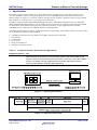
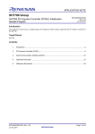
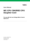
The sample program uses the media access control (MAC) function and Ethernet controller direct memory access
controller (E-DMAC) function of the gigabit Ethernet controller (GETHER) module of the SH7734 to transmit 10
Ethernet frames (see figure 1.2) to another computer (the opposite host computer). With the exception of the preamble,
SFD, and CRC, it is necessary for to user to prepare the transmit data.
The SH7734 supports GMII (Gigabit Media Independent Interface), MII (Media Independent Interface), and RMII
(Reduced Media Independent Interface), but the sample program is targeted at an evaluation board that supports RMII.
For information on the different settings for each of the above interfaces, see the Gigabit Ethernet Controller
(GETHER) section in SH7734 User’s Manual: Hardware (R01UH0233EJ).
The sample program makes settings for 10/100 Mbps transfer using the MAC and E-DMAC functions. It does not make
use of the following functions of the GETHER:
•
•
•
•
•
•
1000 Mbps transfer function using GMII, 10/100 Mbps transfer function using MII
TSU function
CAM function
Flow control
Magic packet detection
Checksum calculation function
Table 1.1
Peripheral Functions Used and Their Applications
Peripheral Function
GETHER
Use
Gigabit Ethernet controller: Connects to a physical layer chip (PHY-LSI) to generate
and resolve Ethernet frames by using the MAC function and transfer data at high
speed to and from the transmit and receive buffers in memory by using the E-DMAC
function. For details, see the Gigabit Ethernet Controller (GETHER) section in
SH7734 User’s Manual: Hardware (R01UH0233EJ).
Figure 1.1 Operating Environment
Figure 1.2 Ethernet Frame Format
R01AN0895EJ0100 Rev.1.00
Aug 30, 2012
Page 2 of 25
SH7734 Group
2.
Example of Ethernet Transmit Settings
Operation Confirmation Conditions
The sample code described in this application note has been confirmed to run normally under the operating conditions
given below.
Table 2.1
Operating Conditions
Item
Microcontroller used
Operating frequency
Operating voltage
Integrated development
environment
C compiler
Version of the sample code
Endian mode
Processing mode
Boot mode
Address extension mode
Memory management unit
(MMU)
Watchdog timer
(WDT)
Board used
3.
Description
SH7734 (R8A77343)
EXTAL input frequency: 33.3333 MHz
CPU clock (clki): 400 MHz
SHwy clock (clks): 200 MHz
SHwy clock (clks1): 100 MHz
DDR clock (MCK0/MCK0#/MCK1/MCK1#): 200 MHz
Bus clock (lkb): 50 MHz
Peripheral clock (clkp): 50 MHz
IO supply power (3.3 V)
Core supply power (1.25 V)
Renesas Electronics
High-performance Embedded Workshop (Version 4.08.00.011)
Renesas Electronics
C/C++ Compiler Package for SuperH Family (V.9.04 release00)
Compiler options:
-cpu=sh4a -endian=little -include="$(PROJDIR)¥inc"
-change_message=warning -object="$(CONFIGDIR)¥$(FILELEAF).obj"
-debug -optimize=0 -gbr=auto -chgincpath -errorpath -global_volatile=0
-opt_range=all -infinite_loop=0 -del_vacant_loop=0 -struct_alloc=1 -nologo
Ver. 1.00
Little endian
Operation in privileged mode only
CS0 boot mode
29-bit
Disabled
Disabled
Renesas Electronics Corporation
SH7734 Evaluation Platform (R0P7734C00000RZ)
Related Application Notes
The following application notes are related to this document and should be referred to when using this application note.
• SH7734 Group: SH7734 Example of Initialization (R01AN0665EJ)
• SH7734 Group: SH7734 Example of Ethernet Receive Settings (R01AN0898EJ)
R01AN0895EJ0100 Rev.1.00
Aug 30, 2012
Page 3 of 25
SH7734 Group
4.
4.1
Example of Ethernet Transmit Settings
Hardware
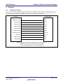
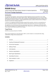
Reference Circuit
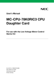
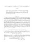
Figure 4.1 is a connection diagram to an Ethernet PHY-LSI for the RMII interface used by the sample program, using
the LAN88710AM manufactured by SMSC as an example. For details of connections to other peripheral circuits, etc.,
see the technical documentation of the SH7734 Evaluation Platform (R0P7734C00000RZ).
SH7734
LAN88710AM
RMII0_TXD_EN
TXEN
RMII0_TXD0
TXD0
RMII0_TXD1
TXD1
RMII0_RXD0
RXD0
RMII0_RXD1
RXD1
RMII0_RX_ER
RXER
RMII0_CRS_DV
CRS_DV
REF50CK
RX_CLK
RMII0_MDIO
MDIO
RMII0_MDC
MDC
Note: This figure shows a conceptual view of connections
between the SH7734 and the PHY chip and differs
from the actual pattern on the printed wiring board.
Figure 4.1 PHY-LSI Connection Example (RMII)
R01AN0895EJ0100 Rev.1.00
Aug 30, 2012
Page 4 of 25
SH7734 Group
4.2
Example of Ethernet Transmit Settings
List of Pins Used
Table 4.1 lists the pins used by the sample program and their functions.
Table 4.1
Pins Used and Their Functions
Pin Name
RMII0_MDC
RMII0_MDIO
RMII0_CRS_DV
RMII0_RX_ER
RMII0_RXD0
RMII0_RXD1
RMII0_TXD_EN
RMII0_TXD0
RMII0_TXD1
REF50CK
I/O
Output
I/O
Input
Input
Input
Input
Output
Output
Output
Input
R01AN0895EJ0100 Rev.1.00
Aug 30, 2012
Description
RMII management data clock
RMII management data I/O
RMII carrier detect
RMII receive error
RMII receive data
RMII receive data
RMII transmit enable
RMII transmit data
RMII transmit data
50 MHz reference clock
Page 5 of 25
SH7734 Group
5.
5.1
Example of Ethernet Transmit Settings
Software
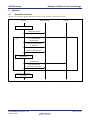
Operation Overview
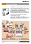
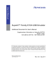
Figure 5.1 is a sequence diagram showing an overview of the operation of the sample program.
SH7734
DDR2-SDRAM
Host PC
Initialize GETHER
Create descriptor list
loop
Copy frame data to
transmit buffer.
Set transmit frame length
in descriptor.
Enable transmit descriptor.
Start transmit
Transmit frame.
Write back transmit
information to descriptor.
End after transmitting
10 frames
Figure 5.1 Sample Program Operation Overview Sequence Diagram
R01AN0895EJ0100 Rev.1.00
Aug 30, 2012
Page 6 of 25
SH7734 Group
5.2
Example of Ethernet Transmit Settings
File Structure
Table 5.1 lists the files used for the sample code. Note that files generated automatically by the integrated development
environment and files from SH7734 Group: SH7734 Example of Initialization (R01AN0665EJ) that are used without
modification are omitted.
Table 5.1
File Structure
File Name
sh7734_main.c
r_ether.c
r_phy.c
dbsct.c
intprg.c
r_ether.h
r_phy.h
typedefine.h
vecttbl.src
Overview
Ethernet transmit main processing module
Ethernet transmit/receive setting module
PHY-LSI automatic negotiation processing
module
Memory initialization
Definition of Ethernet transmit/receive interrupt
handler
Include headers for externally referencing
Ethernet transmit/receive setting module
Include headers for externally referencing PHYLSI automatic negotiation processing module
Declaration headers for variable type names
Exception (reset, general exception, interrupt)
function table, interrupt level setting table during
exception handling
R01AN0895EJ0100 Rev.1.00
Aug 30, 2012
Remarks
Page 7 of 25
SH7734 Group
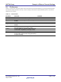
5.3
Example of Ethernet Transmit Settings
List of Constants
Table 5.2 lists the constants used in the sample code.
Table 5.2
Constants Used in Sample Code
Constant
NUM_OF_USER_BUFFER
NUM_OF_TX_DESCRIPTOR
NUM_OF_RX_DESCRIPTOR
NUM_OF_TX_BUFFER
NUM_OF_RX_BUFFER
SIZE_OF_BUFFER
MIN_FRAME_SIZE
MAX_FRAME_SIZE
LOOP_100us
EDMAC_EESIPR_INI_SEND
Setting Value
10
8
8
8
8
1600
60
1514
6700
H'2428 0700
EDMAC_EESIPR_INI_RECV
H'0205 001F
EDMAC_EESIPR_INI_EtherC
H'0040 0000
EtherC_ECSIPR_INI
H'0000 0004
Description
User data area
Transmit descriptor count
Receive descriptor count
Transmit buffer count
Receive buffer count
Buffer size
Min. frame size
Max. frame size
100 µs software wait
GETHER EESIPR transmit setting
Used in interrupt handler to identify transmit interrupt.
GETHER EESIPR receive setting
Used in interrupt handler to identify receive interrupt.
GETHER EESIPR E-MAC status interrupt enable
Used in interrupt handler to identify E-MAC interrupt.
GETHER ECSIPR setting
Constants related to register addresses, constants generated automatically by the integrated development environment,
and constants described in SH7734 Group: SH7734 Example of Initialization (R01AN0665EJ) are not listed in this
document.
R01AN0895EJ0100 Rev.1.00
Aug 30, 2012
Page 8 of 25
SH7734 Group
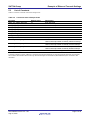
5.4
Example of Ethernet Transmit Settings
List of Structures and Unions
Figure 5.2 lists the structures and unions used in the sample code.
/* ==== Transmit descriptor ==== */
typedef union
{
uint32_t LONG;
struct{
uint32_t TACT:1;
/* Transmit descriptor enabled */
uint32_t TDLE:1;
/* End of transmit descriptor */
uint32_t TFP :2;
/* Location 1, 0 within transmit frame */
uint32_t TFE :1;
/* Transmit frame error */
uint32_t TWBI :1;
/* Write-back completion interrupt notification */
uint32_t reserved1 :16;
/* Reserved */
uint32_t TFS9:1;
/* Transmit FIFO underflow (TCU bit in EESR) */
uint32_t TFS8:1;
/* Transmit abort detect (TABT bit in EESR) */
uint32_t reserved2 :8;
/* Reserved */
}BIT;
} td0_t;
typedef struct
{
#if defined(_BIG)
uint16_t
TDL;
/* Transmit buffer data length (Big endian) */
uint16_t
reserved;
Note: Two versions of the structure are denoted, one
for each endian setting, to enable the order of the
members in the structure to be reversed to match
#else
uint16_t
reserved;
uint16_t
TDL;
the endian mode.
/* Transmit buffer data length (Little endian) */
#endif
} td1_t;
typedef struct
{
uint8_t
*TBA;
/* Address of transmit buffer */
} td2_t;
typedef struct tag_edmac_send_desc
{
td0_t
td0;
td1_t
td1;
td2_t
td2;
struct
tag_edmac_send_desc *pNext;
} edmac_send_desc_t;
/* ==== Receive descriptor ==== */
typedef union
{
uint32_t LONG;
struct{
uint32_t RACT:1;
/* Receive descriptor enabled */
uint32_t RDLE:1;
/* End of receive descriptor */
uint32_t RFP :2;
/* Location 1,0 within receive frame */
uint32_t RFE :1;
/* Receive frame error */
uint32_t PV
/* Padding insertion */
:1;
uint32_t reserved1:16;
/* Reserved */
uint32_t RFS9:1;
/* Receive FIFO overflow (RFOF bit in EESR) */
uint32_t RFS8:1;
/* Receive abort detect (RABT bit in EESR) */
R01AN0895EJ0100 Rev.1.00
Aug 30, 2012
Page 9 of 25
SH7734 Group
Example of Ethernet Transmit Settings
uint32_t RFS7:1;
/* Receive multicast frames (RMAF bit in EESR) */
uint32_t RFS6:1;
/* Carrier extension error (CEEF bit in EESR) */
uint32_t RFS5:1;
/* Carrier extension loss (CELF bit in EESR) */
uint32_t RFS4:1;
/* Residual bits frame receive error (RRF bit in EESR) */
uint32_t RFS3:1;
/* Long frame receive error (RTLE bit in EESR) */
uint32_t RFS2:1;
/* Short frame receive error (RTSF bit in EESR) */
uint32_t RFS1:1;
/* PHY-LSI receive error (PRE bit in EESR) */
uint32_t RFS0:1;
/* Receive frame CRC error detected (CERF bit in EESR) */
}BIT;
} rd0_t;
typedef struct
{
#if defined(_BIG)
uint16_t
RBL;
/* Receive buffer length (Big endian) */
uint16_t
RDL;
/* Receive data length (Big endian) */
Note: Two versions of the structure are denoted, one
for each endian setting, to enable the order of the
members in the structure to be reversed to match
#else
uint16_t
RDL;
/* Receive data length (Little endian) */
uint16_t
RBL;
/* Receive buffer length (Little endian) */
the endian mode.
#endif
} rd1_t;
typedef struct
{
uint8_t *RBA;
/* Receive buffer address */
} rd2_t;
typedef struct tag_edmac_recv_desc
{
rd0_t
rd0;
rd1_t
rd1;
rd2_t
rd2;
struct tag_edmac_recv_desc *pNext;
} edmac_recv_desc_t;
/* ==== The whole transmit/receive descriptors (must be allocated in 16-byte boundaries) ==== */
typedef struct
{
edmac_send_desc_t send[NUM_OF_TX_DESCRIPTOR];
edmac_recv_desc_t recv[NUM_OF_RX_DESCRIPTOR];
edmac_send_desc_t *pSend_top;
/* Registration location of transmit descriptors */
edmac_recv_desc_t *pRecv_end;
/* Registration location and reception end of transmit descriptors */
} txrx_descriptor_set_t;
/* ==== Transmit/receive buffers (must be allocated in 32-byte boundaries) ==== */
/* ---- Definition of all transmit/receive buffer areas ---- */
typedef struct
{
uint8_t send[NUM_OF_TX_BUFFER][SIZE_OF_BUFFER];
uint8_t recv[NUM_OF_RX_BUFFER][SIZE_OF_BUFFER];
} txrx_buffer_set_t;
Figure 5.2 Structures and Unions Used in Sample Code
R01AN0895EJ0100 Rev.1.00
Aug 30, 2012
Page 10 of 25
SH7734 Group
5.5
Example of Ethernet Transmit Settings
List of Variables
Table 5.3 lists the static variables.
Table 5.3
Static Variables
Type
static uint8_t
static uint8_t
static volatile
txrx_descriptor_
set_t
static volatile
txrx_buffer_set_t
5.6
Variable Name
s_frame
mac_addr
eth_desc
Description
Transmit frame data
MAC address
Descriptor area
Used by Function
R_Ether_Write
R_Ether_Open
R_Ether_Write
lan_desc_create
eth_buf
Transmit buffer area
lan_desc_create
List of Functions
Table 5.4 lists the functions.
Table 5.4
FunctionsTable
Function Name
R_Ether_Open
R_Ether_Write
R_Ether_Close
R01AN0895EJ0100 Rev.1.00
Aug 30, 2012
Description
GETHER open function
GETHER frame transmit function
GETHER close function
Page 11 of 25
SH7734 Group
5.7
Example of Ethernet Transmit Settings
Function Specifications
The specifications of the functions of the sample code are listed below.
R_Ether_Open
Overview
Header
Declaration
Description
Arguments
Return values
Notes
R_Ether_Write
Overview
Header
Declaration
Description
Arguments
Return values
Notes
R_Ether_Close
Overview
Header
Declaration
Description
Arguments
Return values
Notes
Initializes the GETHER module.
r_ether.h
int R_Ether_Open(uint32_t ch, uint8_t mac_addr[])
Initializes the GETHER module.
E-MAC channel number
• uint32_t ch
E-MAC MAC address
• uint8_t mac_addr[]
• [R_ETHER_OK(0)]: Open successful
• [R_ETHER_ERROR(-1)]: Open failed
This function initializes the GETHER module, using the MAC address specified as an
argument. When 0 is specified as the MAC address, an address is acquired from the
system in EEPROM, etc. The implementation should match the usage conditions. Note
that the SH7734 provides a single channel as an Ethernet port, so the argument
specifying the E-MAC channel number should be set to 0.
Performs Ethernet frame transmit processing.
r_ether.h
int32_t R_Ether_Write (uint32_t ch, void * buf, uint32_t len)
This function sets the transmit data in the transmit buffer and updates the descriptor
information. The data set in the transmit buffer is transmitted by the E-MAC. If no free
transmit descriptors are available, the function does not wait but returns an error
(R_ETHER_ERROR) and ends. If the transmit data does not constitute 60 bytes, padding
is added.
E-MAC channel number
• uint32_t ch
Transmit data pointer
• void *buf
Ethernet frame length
• uint32_t len
• [R_ETHER_OK(0)]: Normal end
• [R_ETHER_ERROR(-1)]: Error generated
The SH7734 provides a single channel as an Ethernet port, so the argument specifying
the E-MAC channel number should be set to 0.
Resets and stops the GETHER module.
r_ether.h
int R_Ether_Close(uint32_t ch )
Resets and stops the GETHER module.
uint32_t ch
E-MAC channel number
• [R_ETHER_OK(0)]: Close successful
• [R_ETHER_ERROR(-1)]: Close failed
Note that the Ethernet driver of the sample program does not use the
R_ETHER_ERROR(-1) return value. Also, the SH7734 provides a single channel as an
Ethernet port, so the argument specifying the E-MAC channel number should be set to 0.
R01AN0895EJ0100 Rev.1.00
Aug 30, 2012
Page 12 of 25
SH7734 Group
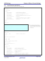
5.8
5.8.1
Example of Ethernet Transmit Settings
Flowcharts
Main Processing
Figure 5.3 is a flowchart of the main processing routine.
Figure 5.3 Main Processing
R01AN0895EJ0100 Rev.1.00
Aug 30, 2012
Page 13 of 25
SH7734 Group
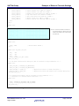
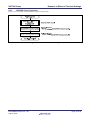
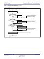
5.8.2
Example of Ethernet Transmit Settings
GETHER Open Processing
Figure 5.4 is a flowchart of the GETHER open processing.
R_Ether_Open
MOD_SEL register = 0000 0000h: Select group A GETHER (RMII).
IPSR4 register = 0001 B6DBh: Select group A GETHER (RMII).
IPSR5 register = 0000 0000h: Select group A GETHER (RMII).
IPSR11 register = 0000 09B0h: Select group A GETHER (RMII).
GPSR2 register = 8000 7C2Fh: Set GETHER (RMII) pins to peripheral function.
Set pin functions
Cancel GETHER module standby
Reset E-MAC/E-DMAC
registers
lan_reg_reset()
MSTPCR1 register
MSTP114 bit = 0: Cancel GETHER module standby.
Reset GETHER module.
Create descriptors
lan_desc_create()
Create transmit/receive descriptors.
Set MAC address
Set arguments in MAHR0 and MAHL0 registers.
Get automatic negotiation result
phy_autonego()
Success?
Get PHY chip automatic negotiation result information.
No
Yes
Set E-MAC/E-DMAC
registers
lan_reg_set()
return(R_ETHER_OK)
return(R_ETHER_ERROR)
Figure 5.4 GETHER Open Processing
R01AN0895EJ0100 Rev.1.00
Aug 30, 2012
Page 14 of 25
SH7734 Group
5.8.3
Example of Ethernet Transmit Settings
GETHER Close Processing
Figure 5.5 is a flowchart of the GETHER close processing routine.
Figure 5.5 GETHER Close Processing
R01AN0895EJ0100 Rev.1.00
Aug 30, 2012
Page 15 of 25
SH7734 Group
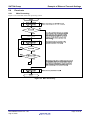
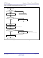
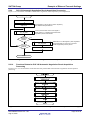
5.8.4
Example of Ethernet Transmit Settings
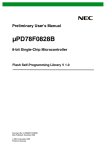
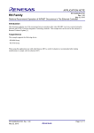
GETHER Frame Transmit Processing
Figure 5.6 is a flowchart of the GETHER frame transmit processing routine.
R_Ether_Write
Yes
Free descriptors
available?
No
Return(R_ETHER_ERROR)
Copy transmit data to transmit
buffer
Transmit data length
≤ min. frame size?
No
Yes
Add padding up to min. frame size
Set transmit data length in
descriptor
Descriptor TACT bit =1
Set descriptor to transmit enable
Confirm
transmit enabled
EDTRR0.TR = 3?
No
Yes
Start transmit
EDTRR0 register
TR bit = 3: Set transmit request.
Update descriptor management
pointer
Return(R_Ether_OK)
Figure 5.6 GETHER Frame Transmit Processing
R01AN0895EJ0100 Rev.1.00
Aug 30, 2012
Page 16 of 25
SH7734 Group
5.8.5
Example of Ethernet Transmit Settings
E-MAC/EDMAC Reset Function
Figure 5.7 is a flowchart of the E-MAC/EDMAC reset function.
Figure 5.7 E-MAC/EDMAC Reset Function
5.8.6
Transmit/Receive Descriptor Initialization Function
Figure 5.8 is a flowchart of the transmit/receive descriptor initialization function.
lan_desc_create
Clear descriptor area to 0
Initialize transmit descriptors
Initialize receive descriptors
Initialize descriptor management
pointers
Clear transmit/receive
buffer to 0
return
Figure 5.8 Transmit/Receive Descriptor Initialization Function
R01AN0895EJ0100 Rev.1.00
Aug 30, 2012
Page 17 of 25
SH7734 Group
5.8.7
Example of Ethernet Transmit Settings
E-MAC/E-DMAC Register Setting Function
Figure 5.9 is a flowchart of the E-MAC/E-DMAC register setting function.
Figure 5.9 E-MAC/E-DMAC Register Setting Function
R01AN0895EJ0100 Rev.1.00
Aug 30, 2012
Page 18 of 25
SH7734 Group
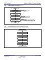
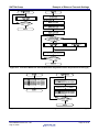
5.8.8
Example of Ethernet Transmit Settings
GETHER Interrupt Handler
Figure 5.10 is a flowchart of the GETHER interrupt handler.
In the sample program presented here, no particular processing is performed.
INT_GEther
Read and clear E-MAC/E-DMAC
status register (EESR)
Transmit-related
interrupt generated?
Yes
No
Receive-related
interrupt generated?
No
At present no interrupt processing
is performed. To use, provide
appropriate program code.
Receive interrupt handler
lan_recv_handler_isr()
At present no interrupt processing
is performed. To use, provide
appropriate program code.
Yes
No
E-MAC-related
interrupt generated?
Transmit interrupt handler
lan_send_handler_isr()
Yes
Clear E-MAC/E-DMAC status
register (ECSR0)
lan_etherc_handler_isr()
Wait 5 Pcyc
At present no interrupt processing
is performed. To use, provide
appropriate program code.
Wait the interrupt priority determination duration.
return
Figure 5.10 GETHER Interrupt Handler
R01AN0895EJ0100 Rev.1.00
Aug 30, 2012
Page 19 of 25
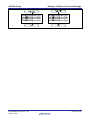
SH7734 Group
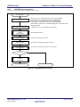
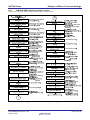
5.8.9
Example of Ethernet Transmit Settings
PHY-LSI Automatic Negotiation Result Acquisition Processing
Figure 5.11 is a flowchart of the PHY-LSI automatic negotiation result acquisition processing routine.
phy_autonego
Reset PHY chip
A wait duration of 50 ms after a reset is required by
the LAN88710AM specifications.
Wait 50 ms
Confirm that the value of bit 5 in MII register 1
(basic status) is 1, indicating that the automatic
negotiation process has finished.
Read MII register 1
phy_reg_read
Automatic
negotiation
finished?
No
No
5 seconds
elapsed?
Yes
Read MII register 5
phy_reg_read
Read bits 8 to 5 in MII register 5 (auto-negotiation
link partner ability) to confirm the connection
modes supported by the link partner.
Get link mode
Yes
return
Figure 5.11 PHY-LSI Automatic Negotiation Result Acquisition Processing
5.8.10
Functions Related to PHY-LSI Automatic Negotiation Result Acquisition
Processing
Figures 5.12 to 5.15 are flowcharts of the functions that perform PHY-LSI automatic negotiation result acquisition
processing.
Figure 5.12 Functions Related to PHY-LSI Automatic Negotiation Result Acquisition Processing (1)
R01AN0895EJ0100 Rev.1.00
Aug 30, 2012
Page 20 of 25
SH7734 Group
Example of Ethernet Transmit Settings
Figure 5.13 Functions Related to PHY-LSI Automatic Negotiation Result Acquisition Processing (2)
Figure 5.14 Functions Related to PHY-LSI Automatic Negotiation Result Acquisition Processing (3)
R01AN0895EJ0100 Rev.1.00
Aug 30, 2012
Page 21 of 25
SH7734 Group
Example of Ethernet Transmit Settings
Figure 5.15 Functions Related to PHY-LSI Automatic Negotiation Result Acquisition Processing (4)
R01AN0895EJ0100 Rev.1.00
Aug 30, 2012
Page 22 of 25
SH7734 Group
5.9
Example of Ethernet Transmit Settings
Section Assignments
Table 5.5 lists the assignments of the sections.
Table 5.5
Section Assignments
Address assignment
Application
Area (virtual address)
Program area (when not otherwise
ROM H'00003000
P0 area (cacheable,
specified)
MMU address
conversion supported)
C
Constant area
ROM
P$PSEC
Section initialization program area
ROM
C$BSEC
Address structure for uninitialized data ROM
C$DSEC
Address structure for initialized data
ROM
D
Initialized data (initial value)
ROM
B
Uninitialized data area
RAM H'0C000000
R
Initialized data area
RAM
PRAM
Target area for copying program (P)
RAM
from ROM
S
Stack area
RAM 0x0FFFF9F0
P1 area (cacheable,
PINTHandler
Exception/interrupt handler
ROM H'80000800
MMU address
VECTTBL
Reset vector table
ROM
conversion not
INTTBL
Interrupt vector table
ROM
supported)
Interrupt mask table
PIntPRG
Interrupt handler
ROM
SP_S
Dedicated stack area for TLB miss
RAM H'8FFFFDF0
handler
RSTHandler
Reset handler
ROM H'A0000000 P2 area (not cacheable,
MMU address
PResetPRG
Reset program
ROM
conversion not
P_LBSC_ROM
ROM program area (for LBSC)
ROM
supported)
P_DBSC3_ROM
ROM program area (for DBSC3)
ROM
PnonCache
Program area (cache-disabled
ROM
access)
BETH_DESC
Ethernet descriptor area
RAM H'AD000000
BETH_BUFF
Ethernet buffer area
RAM H'AD001000
INTTBL_OL
Interrupt mask table copy area
RAM H'E500E000 OL memory
PINTHandler_IL
Exception/interrupt handler copy area RAM H'E5200000 IL memory
PIntPRG_IL
Interrupt handler copy area
RAM
P_LBSC_IL
ROM program copy area (for LBSC)
RAM
Note: For information on the reasons for providing special sections, section copying specifications, etc., see
SH7734 Group: SH7734 Example of Initialization (R01AN0665EJ).
Section
P
R01AN0895EJ0100 Rev.1.00
Aug 30, 2012
Page 23 of 25
SH7734 Group
6.
Example of Ethernet Transmit Settings
Sample Code
The sample code is available for download from the Renesas Electronics Web site.
7.
Reference Documents
• SH7734 Group User’s Manual: Hardware, (R01UH0233EJ) Rev.1.00
(The latest version can be downloaded from the Renesas Electronics Web site.)
• Technical Updates/Technical News
(The latest information can be downloaded from the Renesas Electronics Web site.)
• Integrated Development Environment User’s Manual
Super H C/C++ Compiler Package V.9.04 User’s Manual Rev.1.00
(The latest version can be downloaded from the Renesas Electronics Web site.)
R01AN0895EJ0100 Rev.1.00
Aug 30, 2012
Page 24 of 25
SH7734 Group
Example of Ethernet Transmit Settings
Website and Support
Renesas Electronics Website
http://www.renesas.com/
Inquiries
http://www.renesas.com/inquiry
All trademarks and registered trademarks are the property of their respective owners.
R01AN0895EJ0100 Rev.1.00
Aug 30, 2012
Page 25 of 25
Revision Record
Rev.
1.00
Date
Aug.30.12
Description
Page
Summary
—
First edition issued
A-1
General Precautions in the Handling of MPU/MCU Products
The following usage notes are applicable to all MPU/MCU products from Renesas. For detailed usage notes on the
products covered by this manual, refer to the relevant sections of the manual. If the descriptions under General
Precautions in the Handling of MPU/MCU Products and in the body of the manual differ from each other, the
description in the body of the manual takes precedence.
1. Handling of Unused Pins
Handle unused pins in accord with the directions given under Handling of Unused Pins in the manual.
⎯ The input pins of CMOS products are generally in the high-impedance state. In operation with an
unused pin in the open-circuit state, extra electromagnetic noise is induced in the vicinity of LSI, an
associated shoot-through current flows internally, and malfunctions occur due to the false
recognition of the pin state as an input signal become possible. Unused pins should be handled as
described under Handling of Unused Pins in the manual.
2. Processing at Power-on
The state of the product is undefined at the moment when power is supplied.
⎯ The states of internal circuits in the LSI are indeterminate and the states of register settings and
pins are undefined at the moment when power is supplied.
In a finished product where the reset signal is applied to the external reset pin, the states of pins
are not guaranteed from the moment when power is supplied until the reset process is completed.
In a similar way, the states of pins in a product that is reset by an on-chip power-on reset function
are not guaranteed from the moment when power is supplied until the power reaches the level at
which resetting has been specified.
3. Prohibition of Access to Reserved Addresses
Access to reserved addresses is prohibited.
⎯ The reserved addresses are provided for the possible future expansion of functions. Do not access
these addresses; the correct operation of LSI is not guaranteed if they are accessed.
4. Clock Signals
After applying a reset, only release the reset line after the operating clock signal has become stable.
When switching the clock signal during program execution, wait until the target clock signal has
stabilized.
⎯ When the clock signal is generated with an external resonator (or from an external oscillator)
during a reset, ensure that the reset line is only released after full stabilization of the clock signal.
Moreover, when switching to a clock signal produced with an external resonator (or by an external
oscillator) while program execution is in progress, wait until the target clock signal is stable.
5. Differences between Products
Before changing from one product to another, i.e. to one with a different type number, confirm that the
change will not lead to problems.
⎯ The characteristics of MPU/MCU in the same group but having different type numbers may differ
because of the differences in internal memory capacity and layout pattern. When changing to
products of different type numbers, implement a system-evaluation test for each of the products.
Notice
1.
Descriptions of circuits, software and other related information in this document are provided only to illustrate the operation of semiconductor products and application examples. You are fully responsible for
the incorporation of these circuits, software, and information in the design of your equipment. Renesas Electronics assumes no responsibility for any losses incurred by you or third parties arising from the
use of these circuits, software, or information.
2.
Renesas Electronics has used reasonable care in preparing the information included in this document, but Renesas Electronics does not warrant that such information is error free. Renesas Electronics
3.
Renesas Electronics does not assume any liability for infringement of patents, copyrights, or other intellectual property rights of third parties by or arising from the use of Renesas Electronics products or
assumes no liability whatsoever for any damages incurred by you resulting from errors in or omissions from the information included herein.
technical information described in this document. No license, express, implied or otherwise, is granted hereby under any patents, copyrights or other intellectual property rights of Renesas Electronics or
others.
4.
You should not alter, modify, copy, or otherwise misappropriate any Renesas Electronics product, whether in whole or in part. Renesas Electronics assumes no responsibility for any losses incurred by you or
5.
Renesas Electronics products are classified according to the following two quality grades: "Standard" and "High Quality". The recommended applications for each Renesas Electronics product depends on
third parties arising from such alteration, modification, copy or otherwise misappropriation of Renesas Electronics product.
the product's quality grade, as indicated below.
"Standard": Computers; office equipment; communications equipment; test and measurement equipment; audio and visual equipment; home electronic appliances; machine tools; personal electronic
equipment; and industrial robots etc.
"High Quality": Transportation equipment (automobiles, trains, ships, etc.); traffic control systems; anti-disaster systems; anti-crime systems; and safety equipment etc.
Renesas Electronics products are neither intended nor authorized for use in products or systems that may pose a direct threat to human life or bodily injury (artificial life support devices or systems, surgical
implantations etc.), or may cause serious property damages (nuclear reactor control systems, military equipment etc.). You must check the quality grade of each Renesas Electronics product before using it
in a particular application. You may not use any Renesas Electronics product for any application for which it is not intended. Renesas Electronics shall not be in any way liable for any damages or losses
incurred by you or third parties arising from the use of any Renesas Electronics product for which the product is not intended by Renesas Electronics.
6.
You should use the Renesas Electronics products described in this document within the range specified by Renesas Electronics, especially with respect to the maximum rating, operating supply voltage
range, movement power voltage range, heat radiation characteristics, installation and other product characteristics. Renesas Electronics shall have no liability for malfunctions or damages arising out of the
use of Renesas Electronics products beyond such specified ranges.
7.
Although Renesas Electronics endeavors to improve the quality and reliability of its products, semiconductor products have specific characteristics such as the occurrence of failure at a certain rate and
malfunctions under certain use conditions. Further, Renesas Electronics products are not subject to radiation resistance design. Please be sure to implement safety measures to guard them against the
possibility of physical injury, and injury or damage caused by fire in the event of the failure of a Renesas Electronics product, such as safety design for hardware and software including but not limited to
redundancy, fire control and malfunction prevention, appropriate treatment for aging degradation or any other appropriate measures. Because the evaluation of microcomputer software alone is very difficult,
please evaluate the safety of the final products or systems manufactured by you.
8.
Please contact a Renesas Electronics sales office for details as to environmental matters such as the environmental compatibility of each Renesas Electronics product. Please use Renesas Electronics
products in compliance with all applicable laws and regulations that regulate the inclusion or use of controlled substances, including without limitation, the EU RoHS Directive. Renesas Electronics assumes
no liability for damages or losses occurring as a result of your noncompliance with applicable laws and regulations.
9.
Renesas Electronics products and technology may not be used for or incorporated into any products or systems whose manufacture, use, or sale is prohibited under any applicable domestic or foreign laws or
regulations. You should not use Renesas Electronics products or technology described in this document for any purpose relating to military applications or use by the military, including but not limited to the
development of weapons of mass destruction. When exporting the Renesas Electronics products or technology described in this document, you should comply with the applicable export control laws and
regulations and follow the procedures required by such laws and regulations.
10. It is the responsibility of the buyer or distributor of Renesas Electronics products, who distributes, disposes of, or otherwise places the product with a third party, to notify such third party in advance of the
contents and conditions set forth in this document, Renesas Electronics assumes no responsibility for any losses incurred by you or third parties as a result of unauthorized use of Renesas Electronics
products.
11. This document may not be reproduced or duplicated in any form, in whole or in part, without prior written consent of Renesas Electronics.
12. Please contact a Renesas Electronics sales office if you have any questions regarding the information contained in this document or Renesas Electronics products, or if you have any other inquiries.
(Note 1)
"Renesas Electronics" as used in this document means Renesas Electronics Corporation and also includes its majority-owned subsidiaries.
(Note 2)
"Renesas Electronics product(s)" means any product developed or manufactured by or for Renesas Electronics.
http://www.renesas.com
SALES OFFICES
Refer to "http://www.renesas.com/" for the latest and detailed information.
Renesas Electronics America Inc.
2880 Scott Boulevard Santa Clara, CA 95050-2554, U.S.A.
Tel: +1-408-588-6000, Fax: +1-408-588-6130
Renesas Electronics Canada Limited
1101 Nicholson Road, Newmarket, Ontario L3Y 9C3, Canada
Tel: +1-905-898-5441, Fax: +1-905-898-3220
Renesas Electronics Europe Limited
Dukes Meadow, Millboard Road, Bourne End, Buckinghamshire, SL8 5FH, U.K
Tel: +44-1628-651-700, Fax: +44-1628-651-804
Renesas Electronics Europe GmbH
Arcadiastrasse 10, 40472 Düsseldorf, Germany
Tel: +49-211-65030, Fax: +49-211-6503-1327
Renesas Electronics (China) Co., Ltd.
7th Floor, Quantum Plaza, No.27 ZhiChunLu Haidian District, Beijing 100083, P.R.China
Tel: +86-10-8235-1155, Fax: +86-10-8235-7679
Renesas Electronics (Shanghai) Co., Ltd.
Unit 204, 205, AZIA Center, No.1233 Lujiazui Ring Rd., Pudong District, Shanghai 200120, China
Tel: +86-21-5877-1818, Fax: +86-21-6887-7858 / -7898
Renesas Electronics Hong Kong Limited
Unit 1601-1613, 16/F., Tower 2, Grand Century Place, 193 Prince Edward Road West, Mongkok, Kowloon, Hong Kong
Tel: +852-2886-9318, Fax: +852 2886-9022/9044
Renesas Electronics Taiwan Co., Ltd.
13F, No. 363, Fu Shing North Road, Taipei, Taiwan
Tel: +886-2-8175-9600, Fax: +886 2-8175-9670
Renesas Electronics Singapore Pte. Ltd.
80 Bendemeer Road, Unit #06-02 Hyflux Innovation Centre Singapore 339949
Tel: +65-6213-0200, Fax: +65-6213-0300
Renesas Electronics Malaysia Sdn.Bhd.
Unit 906, Block B, Menara Amcorp, Amcorp Trade Centre, No. 18, Jln Persiaran Barat, 46050 Petaling Jaya, Selangor Darul Ehsan, Malaysia
Tel: +60-3-7955-9390, Fax: +60-3-7955-9510
Renesas Electronics Korea Co., Ltd.
11F., Samik Lavied' or Bldg., 720-2 Yeoksam-Dong, Kangnam-Ku, Seoul 135-080, Korea
Tel: +82-2-558-3737, Fax: +82-2-558-5141
© 2012 Renesas Electronics Corporation. All rights reserved.
Colophon 2.2