1
Development of generic slow control producers for the
EUDAQ framework
Nis Meinert, Deutsches Elektronen-Synchrotron, Germany
September 11, 2014
Abstract
This report documents the implementation and shows the usage of a producer
for the EUDAQ-framework, which allows to handle slow control devices. The
configuration and readout of this devices can be managed in a generic way by
creating minimalistic properties files and without any need of changing EUDAQ’s
C++ source code.
1
Contents
1 Introduction
1.1 The architecture of the EUDAQ-framework . . . . . . . . . . . . . . . . .
3
3
2 Slow Control Producer
2.1 Generic Slow Control Producer . . . . . . . . . . . . . . . . . . . . . . .
2.2 The device configuration in detail . . . . . . . . . . . . . . . . . . . . . .
2.3 The producer configuration in detail . . . . . . . . . . . . . . . . . . . .
4
4
6
7
3 Implementation
3.1 Overview . . . . . . . . . . . .
3.2 SlowControlProducer . . . . .
3.2.1 Method: OnConfigure
3.2.2 Method: OnStartRun .
3.2.3 Method: OnStopRun .
3.2.4 Method: OnTerminate
3.2.5 Readout loop . . . . .
3.3 SerialCommunicator . . . . .
3.4 LazyDeviceReader . . . . . .
3.5 CommandFactory . . . . . . .
3.6 ExceptionFactory . . . . . . .
.
.
.
.
.
.
.
.
.
.
.
.
.
.
.
.
.
.
.
.
.
.
.
.
.
.
.
.
.
.
.
.
.
2
.
.
.
.
.
.
.
.
.
.
.
.
.
.
.
.
.
.
.
.
.
.
.
.
.
.
.
.
.
.
.
.
.
.
.
.
.
.
.
.
.
.
.
.
.
.
.
.
.
.
.
.
.
.
.
.
.
.
.
.
.
.
.
.
.
.
.
.
.
.
.
.
.
.
.
.
.
.
.
.
.
.
.
.
.
.
.
.
.
.
.
.
.
.
.
.
.
.
.
.
.
.
.
.
.
.
.
.
.
.
.
.
.
.
.
.
.
.
.
.
.
.
.
.
.
.
.
.
.
.
.
.
.
.
.
.
.
.
.
.
.
.
.
.
.
.
.
.
.
.
.
.
.
.
.
.
.
.
.
.
.
.
.
.
.
.
.
.
.
.
.
.
.
.
.
.
.
.
.
.
.
.
.
.
.
.
.
.
.
.
.
.
.
.
.
.
.
.
.
.
.
.
.
.
.
.
.
.
.
.
.
.
.
.
.
.
.
.
.
.
.
.
.
.
.
.
.
.
.
.
.
8
8
8
9
9
9
9
10
10
11
12
12
1 Introduction
The EUDAQ framework[1] is a generic data acquisition framework (DAQ) for detector
R&D (research and development) at test beams, with special focus on collecting data
from test beam telescopes. EUDAQ 1 had a trigger based layout. One hardware trigger
needed to be spread to all devices and by that limited the data rate by the slowest device.
Due to that, all data were taken at the same frequency, leaving no option to provide a
readout of e.g. temperature sensors, damp sensors, power supplies or others, so called
Slow Control devices. While, for example, tracking positions are taken at frequencies
up to 1 MHz, a readout of slow control devices at a frequency of 1 Hz is reasonable.
A readout with higher frequencies is neither necessary nor possible for such devices
(unnecessarily data duplication). Due to the fact that EUDAQ 1 did not support such
kind of slow control devices, a separate and often manual readout (without EUDAQ)
was necessary.
With EUDAQ 2 the old data format was replaced by a format, which allows multiple
triggers beeing associated with one single readout and by that allowing the implementation of Slow Control Producers.
In the EUDAQ framework the part which takes care of the hardware interaction
is called a producer. A producer encapsulates the communication with the hardware,
initializes it and manages the data readout. This report shows the implementation and
usage of a generic slow control producer, which allows customers to easily configure
initializing and data acquisition of arbitrary slow control devices. These configuration
can be done in a generic way by creating minimalistic properties files, without the need
of changing EUDAQ’s C++ source code.
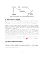
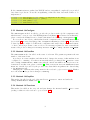
1.1 The architecture of the EUDAQ-framework
The EUDAQ-framework is build in a very modular way. All processes and especially the
hardware specific parts, are separated, which allows the framework to work with many
different kinds of hardware by just adding new or changing a few existing modules. In
figure 1 the most relevant parts of this project are shown. Each one of this modules can
be compiled independently and run separately on different devices. The communication
is realized via TCP/IP.
The main focus for this project lies on the producer and its interaction with the
hardware. A producer handles the receiving of commands from the RunControl, the
sending of data to the DataCollector and it encapsulates the Communication with the
hardware. Each of this hardware devices is controlled by one producer and each producer
can manage multiple devices. Apart from configuration a producer collects data from
his assigned hardware and sends them to a DataCollector. Similar to a producer a
DataCollector can handle multiple producers, bundle their incoming data streams and
writes them to storage.
A producer (as well as all other EUDAQ parts) gets configured by the RunControl.
The RunControl sends commands to all connected processes and receives their status.
3
Figure 1: Relevant parts of the EUDAQ-framework architecture.
2 Slow Control Producer
Within the old data format in EUDAQ 1, there was only one existing kind of producer.
These producers were made to readout hardware at the highest possible frequency (but
still common for all devices and limited by the slowest device). A trigger, given by
four scintillator detectors in the telescope correspond to one readout of a producer, so
that the slowest device limited this rate. This behavior is reasonable for e.g. tracking
data but not necessary for data which do not directly correspond to a specific hit in the
detector due to it very slow change. Such kind of slow changing data could be values
like temperature or air humidity.
Because it was neither reasonable, nor–for some devices–even possible to readout
such slow changing data at high frequencies by producers, it was done without the
EUDAQ-framework, sometimes even manual. The new data format of EUDAQ 2 fixes
this grievance and finally allows the data taking of this, even when they are not corresponding to a particular hit in the telescope, important data for the measurement and
controlling. The implementation of this slow changing data taking producer is called
Slow Control Producer.
So the task of a slow control producers is roughly the same as for a normal producer:
initialize the device in the beginning and readout some quantity at a given, slow frequency. The communication is realized via serial ports1 and just differs in the name of
the commands.
2.1 Generic Slow Control Producer
The idea for the implementation of generic slow control producers is to define all necessary commands (as well as queries and their response pattern) in a separate device
configuration file. Each command can be identified and referenced by a given key name.
1
in fact a serial ports can be just emulated and with that encapsulate the real communication e.g. via
USB
4
Supplementary this device configuration provides other hardware specific information,
for example the requested baud rate of the connection.
Another producer configuration file refers to–possible multiple–device configurations
and lists the keys and values for initial commands, as well as queries for the readout
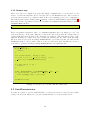
loop. The achievement of this design is, that the producer logic is completely extracted
to configuration files, so that there is no need for multiple (slow control) producer implementation as EUDAQ C++ classes. To define new producers or even devices it is enough
to plug in new configuration files with no need of recompiling the framework or editing internal code (compare figure 2). Furthermore, this configuration can be extremely
minimal by just focusing on the real producer logic.
Figure 2: Construction of a generic producer by configuration files. The fact, that one
producer configuration can refer to multiple device configuration files is not
shown.
An example of a device- and producer-configuration for the TTi QL355TP Power
Supply[2] is shown in listing 1 and listing 2. The producer configuration is an excerpt of a
general configuration file, which is sent by the RunControl to all processes.
5
1
2
3
4
5
[CONNECTION]
baudRate
characterSize
sendTwoStopBits
enableParity
=
=
=
=
9600
8
false
false
6
7
8
9
10
[COMMANDS]
g e t V o l t a g e c h 1 . command = V1?
g e t V o l t a g e c h 1 . r e g e x p = V1 [ 0 − 9 ] ∗ \ . [ 0 − 9 ] ∗
g e t V o l t a g e c h 1 . p a t t e r n = $3
11
12
13
14
g e t V o l t a g e c h 2 . command = V2?
g e t V o l t a g e c h 2 . r e g e x p = V2 [ 0 − 9 ] ∗ \ . [ 0 − 9 ] ∗
g e t V o l t a g e c h 2 . p a t t e r n = $3
15
16
17
s e t V o l t a g e c h 1 = V1 $
s e t V o l t a g e c h 2 = V2 $
Listing 1: example for a device configuration: ttiCPX400.config
1
2
3
4
5
6
7
[ Producer . SlowControlExample ]
a c o n f i g = ttiCPX400 . c o n f i g
a p o r t = / dev /ttyACM0
a command 1 = s e t V o l t a g e c h 1 , 0 . 1
a command 2 = s e t V o l t a g e c h 2 , 0 . 2
a q u e r y 1 = g e t V o l t a g e c h 1 , c o r e v o l t a g e , 2000
a q u e r y 2 = g e t V o l t a g e c h 2 , i m p o r t a n t v o l t a g e , 1337
8
9
b config = . . .
Listing 2: example for a producer configuration
2.2 The device configuration in detail
The device configuration consists of three parts. At first some general connection parameters
have to been set. The type of this parameters is given by the connection, the values are given
by the device. Secondary, initial commands have to been executed to set the device in a proper
initial state. Afterwards (third) queries for a readout loop, which provide the measured values
for this device have to been defined.
Necessary types of connection parameters for devices connected via (emulated) serial ports
are the same and do not differ between arbitrary devices:
baud rate Symbol rate or modulation rate in symbols per second.
character size Number of data bits in each character.
stop bits Stop bits showing the end of a signal. Devices can send one, one-and-one half or two
stop bits (most devices uses one stop bit).
parity Additional data bit is sent with each character bit to detect corrupted transmissions.
6
Commands are specific for every device. Nevertheless they have very similar patterns and
therefor they can be grouped into two different types, Commands and Queries: A (plain)
command does not have a response from the device. For a power supply this could be commands like: setting the voltage of a specific channel to a certain value For example for the
TTi QL355TP Power Supply this command could be (compare with the manual [2]):
V1 42.0
setting the voltage of channel 1 to 42 V. The device won’t send a response. To get the current
voltage of channel 1 of the TTi QL355TP Power Supply, one have to send the command:
V1?
This device will answer quickly:
V1 42.0000
A command, which expects and answer to been sent afterwards is called a query.
The device configuration (listing 1) defines two queries and two commands and associate
the keys getVoltage ch1, getVoltage ch2 and setVoltage ch1, setVoltage ch2 for them2 .
Each query contains three fields:
command This is the actual command which will be sent to the device.
regexp The regular expression of the expected answer. This can be an arbitrary regular
expression without using capture groups (this feature is not yet implemented).
pattern This defines the concrete structure of the value which gets returned. The n-th appearance of the $-symbol will be replaced by the n-th mapping result of the given regular
expression. An additional number k can be given to truncate the first k characters of
the return statement (given no number at all is equivalent to k = 0). Let’s assume a
regular expression maps on “42” and “abc 13.37”. Using a pattern “measured: $ and $4
au” makes the return string to be: “measured: 42 and 13.37 au”. To return the response
without any formating at all, the pattern has to be set to “$”.
2.3 The producer configuration in detail
The producer configuration (listing 2) can load different kind of devices. Each device (enumerate alphanumerical) has its own device configuration file (line 2) and is bound to a specific
port (line 3). Initial commands are listed as commands and queries for the readout loop as
querys. Each query (as well as commands), refers directly to a command, which is defined
in its specific device configuration file. Furthermore, each query is associated with a tag label
which represent the physical meaning of this value (e.g. core voltage in line 6) and a readout
frequency in milliseconds.
Each $-symbol of a command (not a query) in the device configuration file will be replaced
by the value, given in the producer configuration file (compare line 4 and line 5).
2
all leading and ending spaces, tabs, etc. of values and keys gets cut off for all properties
7
3 Implementation
In the following code examples the namespace std was removed to not produce avoidable line
breaks. In case of insecurity please compare the source code.
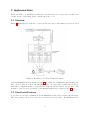
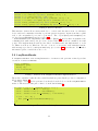
3.1 Overview
Figure 3 summarize the work flow of a Slow Control Producer. The managed devices are used
Figure 3: Work flow of a Slow Control Producer
as SerialCommunicators (compare section 3.3) to enable the communication via serial ports.
The collected data are sent to the DataCollector. At every stage possible errors, due to
malformed configuration files or connection problems are thrown back to the producer. The
messages of the errors are generated by the ExceptionFactory (compare section 3.6).
3.2 SlowControlProducer
A producer receives its commands from the RunControl and sends back his current status.
The data getting collected by a producer from his devices are sent to the DataCollector.
8
Both communications are realized via TCP/IP and are encapsulated completely by a provided
base class for producers. To use the encapsulating of this base class, four methods have to be
implemented:
1
2
3
4
virtual
virtual
virtual
virtual
void
void
void
void
OnConfigure ( c o n s t eudaq : : C o n f i g u r a t i o n &c o n f i g ) ;
OnStartRun ( u n s i g n e d param ) ;
OnStopRun ( v o i d ) ;
OnTerminate ( v o i d ) ;
3.2.1 Method: OnConfigure
The OnConfigure method is called to provide the producer with a global configuration file,
which is sent to every process of the EUDAQ-framework (listing 2 was extracted from this file)–
please consider the manual for more detailed information about eudaq::Configuration[1].
For every slow control device, which is listed in the configuration file, a SerialCommunicator
(see section 3.3) is created and plugged into a LazyDeviceReader (see section 3.4). In case, that
a desired property couldn’t be found in the configuration file, maybe due to malformed syntax,
or other connection problems occurs, a verbose error message is printed to std::cerr and the
status of the producer changes from eudaq::Status::LVL OK to eudaq::Status::LVL ERROR.
3.2.2 Method: OnStartRun
The OnStartRun method is called on the start of each run. The parameter param is the run
number of the started run.
A producer is a state machine and this method changes the status of this machine from
“configured” to “running”. For that some internal values get changed like started = true
and a eudaq::RawDataEvent::BORE event with the current run number is sent (for more information about this event, please consider [1]). This event is sent via void SendEvent(const
Event &), a method provided by the producer base class which encapsulates the data sending
to the DataCollector.
Changing the started value is important for the readout loop (see section 3.2.5). Further
more the status of the producer changes to Running.
3.2.3 Method: OnStopRun
This method is called at the end of the run. It sets started = false and sends the
eudaq::RawDataEvent::EORE event [1].
3.2.4 Method: OnTerminate
This method is called at the very end and just changes the internal variable done = true
(ending condition for the readout loop–see section 3.2.5).
9
3.2.5 Readout loop
After a producer is configured properly and initial commands have been executed, it can
start to readout the hardware and to send the data to the DataCollector. The readout is
performed in a readout loop, which is called at the very beginning (even before configuration
has started) and is started with setting started = true by OnStartRun (compare listing 3,
lines 2-4). A time depending readout logic is realized by LazyDeviceReader which provides a
lazyEnrichData method:
v o i d l a z y E n r i c h D a t a ( v e c t o r <p a i r <s t r i n g , s t r i n g >> &) ;
Every encapsulated measured value of a LazyDeviceReader has been mapped to it’s own
readout frequency. If the time difference between the last readout and the current time is
greater than this given frequency, the data list gets enriched. The data list is a list of the
physical meaning of a value, stored as a string tag (first) and the value itself (second).
All new data are stored in an eudaq::RawDataEvent object (line 17) and get sent via the
SendEvent method. It is possible, that no device provides new data. In this case it is not
reasonable to generate an empty eudaq::RawDataEvent object (lines 11-13).
1
2
3
4
w h i l e ( ! done ) {
i f (! started ) {
continue ;
}
5
v e c t o r <p a i r <s t r i n g , s t r i n g >> data ;
f o r ( i n t i = 0 ; i < d e v i c e s . s i z e ( ) ; i ++) {
d e v i c e s [ i ] . l a z y E n r i c h D a t a ( data ) ;
}
6
7
8
9
10
i f ( data . s i z e ( ) == 0 ) {
continue ;
}
11
12
13
14
eudaq : : RawDataEvent e v e n t (EVENT TYPE,
f o r ( p a i r <s t r i n g , s t r i n g > p : data ) {
e v e n t . SetTag ( p . f i r s t , p . s e c o n d ) ;
}
15
16
17
18
run ,
ev ) ;
19
SendEvent ( e v e n t ) ;
20
21
}
Listing 3: readout loop of SlowControlProducer.cxx
3.3 SerialCommunicator
To make it possible to provide different kinds of connections for slow control producers (like
serial ports, network, infrared etc.), a pure virtual interface for devices is introduced.
10
1
2
3
4
5
6
7
virtual
virtual
virtual
virtual
virtual
virtual
virtual
˜ D ev ic e ( v o i d ) { } ;
v o i d c o n n e c t ( v o i d ) throw ( r u n t i m e e r r o r ) = 0 ;
bool connected ( void ) const = 0 ;
v o i d d i s c o n n e c t ( v o i d ) throw ( r u n t i m e e r r o r ) = 0 ;
v o i d send ( c o n s t Query &) throw ( r u n t i m e e r r o r ) = 0 ;
s t r i n g pl a i nR e a d ( v o i d ) throw ( r u n t i m e e r r o r ) = 0 ;
s t r i n g query ( c o n s t RichQuery &) throw ( r u n t i m e e r r o r ) = 0 ;
Listing 4: Device interface
This interface defines all necessary methods, to connect and disconnect from one arbitrary
device and send commands via send or perform queries via query. Apart from this, a plain
read to the encapsulated port can be performed. The objects Query and RichQuery are
produced in a CommandFactory (see section 3.5).
SerialCommunicator implements this interface (listing 4) and by that encapsulates the
communication with serial ports (for some devices USB connections are emulated as serial
ports). The implementation itself is some kind of technical and was implemented to work
for Linux as well as for Windows. In case of errors or exceptions, std::runtime errors,
with messages produced by ExceptionFactory (see section 3.6) gets thrown. For further
information please consider the source code.
3.4 LazyDeviceReader
A LazyDeviceReader owns an implementation of a Device and performs a time-dependent
execution of struct Commands:
1
2
3
4
5
s t r u c t Command {
RichQuery query ;
s t r i n g tag ;
long readouttime ;
};
Listing 5: Extract from LazyDeviceReader implementation.
These three variables realize the three variables which are passed in the producer configuration
file (compare listing 2).
The magic of a lazy read is performed, as already described above, in the lazyEnrichData
method. The most relevant part of this code is shown in listing 6.
1
2
3
4
for ( int
chrono
chrono
chrono
i
::
::
::
= 0 ; i < commands . s i z e ( ) ; i ++) {
m i l l i s e c o n d s t1 = time [ i ] ;
m i l l i s e c o n d s t 2 = currentTime ( ) ;
m i l l i s e c o n d s dt ( commands [ i ] . r e a d o u t t i m e ) ;
5
i f ( t 2 − t 1 > dt ) {
data . push back ( readoutAndSetTime ( i ) ) ;
}
6
7
8
9
}
Listing 6: Extract from the lazyEnrichData method.
11
The pair<string, string> readoutAndSetTime(const unsigned ID) method executes the
specific command, returns the formated answer and sets the readout time of the command to
the current time via time[ID] = currentTime().
If it is necessary to have access to the encapsulated Device object, this can be performed by
the shared ptr<Device> device(void) method. This can be usefully, for example if there is
need to call the disconnect method of a device. The complete interface of LazyDeviceReader
is shown in listing 7.
3.5 CommandFactory
The interface of the CommandFactory is shown in listing 8. The CommandFactory allows the
production of Querys and RichQuerys. A Query only encapsulate one command string and is
the base class of RichQuery. Besides this command string, a RichQuery also stores the regular
expression and the pattern of a query to generate the formated answer (compare section 2.1).
To generate a command, it is enough to call generateQuery with a desired command and
optional with values (args), which will replace all occurrences of the character target. Analog
to this, a query can be generated by calling generateQuery. RichQuery stores all relevant
information to generate the formated answer via the generateAnswer method.
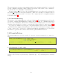
3.6 ExceptionFactory
The ExceptionFactory provides a method to generate exception messages in a common format.
1
2
3
4
5
s t r i n g g e n e r a t e M e s s a g e ( c o n s t s t r i n g msg ,
const s t r i n g filename ,
const int l i n e ) {
r e t u r n ” [ ” + f i l e n a m e + ” − l i n e : ” + t o s t r i n g ( l i n e ) + ” ] ” + msg ;
}
A call to this method could look like:
1
2
throw E x c e p t i o n F a c t o r y : : g e n e r a t e M e s s a g e ( ” Something went t e r r i b l y wrong ” ,
FILE ,
LINE ) ;
leading to the following exception message: [MyClass.cpp - 42] Something went terribly
wrong.
12
13
16
15
14
13
12
11
10
9
8
7
6
5
4
3
2
1
9
8
7
6
5
4
3
2
1
Listing 8: CommandFactory interface
s t a t i c s t r i n g generateAnswer ( c o n s t s t r i n g &answer , c o n s t s t r i n g ®exp , c o n s t s t r i n g &p a t t e r n ,
c o n s t c h a r t a r g e t = TARGET) throw ( i n v a l i d a r g u m e n t ) ;
s t r i n g &command , c o n s t s t r i n g ®exp , c o n s t s t r i n g &p a t t e r n ) ;
s t r i n g &command , c o n s t s t r i n g ®exp , c o n s t s t r i n g &p a t t e r n ,
s t r i n g &arg , c o n s t c h a r t a r g e t = TARGET) ;
s t r i n g &command , c o n s t s t r i n g ®exp , c o n s t s t r i n g &p a t t e r n ,
v e c t o r <s t r i n g > &a r g s , c o n s t c h a r t a r g e t = TARGET) ;
s t r i n g &command ) ;
s t r i n g &command , c o n s t s t r i n g &arg ,
c h a r t a r g e t = TARGET) ;
s t r i n g &command , c o n s t v e c t o r <s t r i n g > &a r g s ,
c h a r t a r g e t = TARGET) ;
s t a t i c RichQuery g e n e r a t e Q u e r y ( c o n s t
s t a t i c RichQuery g e n e r a t e Q u e r y ( c o n s t
const
s t a t i c RichQuery g e n e r a t e Q u e r y ( c o n s t
const
s t a t i c Query g e n e r a t e Q u e r y ( c o n s t
s t a t i c Query g e n e r a t e Q u e r y ( c o n s t
const
s t a t i c Query g e n e r a t e Q u e r y ( c o n s t
const
s t a t i c c o n s t c h a r TARGET = ’ $ ’ ;
Listing 7: LazyDeviceReader interface
LazyDeviceReader ( s h a r e d p t r <Device >, s t r u c t Command &) ;
LazyDeviceReader ( s h a r e d p t r <Device >, v e c t o r <s t r u c t Command> &commands ) ;
v o i d l a z y E n r i c h D a t a ( v e c t o r <p a i r <s t r i n g , s t r i n g >> &) throw ( r u n t i m e e r r o r ) ;
s t r u c t Command {
RichQuery query ;
s t r i n g tag ;
long readouttime ;
};
Acknowledgements
I would like to express my sincere gratitude to my adviser Dipl.-Phys. Richard Peschke for the
continuous support and for his patience, motivation, enthusiasm, and deep knowledge about
the EUDAQ-framework and C++11. His guidance helped me all time of project work. I am
sure it would have not been possible without his help.
I wish to thank my parents for their undivided support and interest who inspired me and
encouraged me to go my own way and enable me my study.
At last but not the least I want to thank all summer students, especially my room mate
Harald Viemann, for having such a great time. You provided the necessary state of distraction,
to love my work without going crazy.
Thanking you.
14
References
[1] EUDAQ Development Team, EUDAQ Software User Manual
URL: http://eudaq.github.io/manual/EUDAQUserManual.pdf
[2] Thurlby Thandar Instruments, TTi QL355TP Power Supply Manual
URL: http://docs-europe.electrocomponents.com/webdocs/0a59/0900766b80a5946f.pdf
15