1
ISSN 0280-5316
ISRN LUTFD2/TFRT--5910--SE
Control of a Quadrotor
Niklas Hansson
Mikael Rudner
Lund University
Department of Automatic Control
May 2011
Lund University
Department of Automatic Control
Box 118
SE-221 00 Lund Sweden
Document name
MASTER THESIS
Date of i ssue
May 2011
Document Number
ISRN LUTFD2/TFRT--5910--SE
Author (s)
Super vi sor
Niklas Hansson
Mikael Rudner
Anders Robertsson, Dept. of Automatic Control, Lund
University, Sweden
Karl-Erik Årzén, Dept. of Automatic Control, Lund
University, Sweden (examiner)
Sponsor i ng organi zati on
Ti tl e and subtitl e
Control of a Quadrotor
Abstr act
The objective of this thesis is to investigate the use of commercial devices as user interfaces on a quadrotor and to
investigate solutions to the problem of slung load control. A slung load is a uniform mass attached with a wire which is
allowed to swing freely to the bottom of the quadrotor. The purpose of substituting the radio control (RC) controller with
a commercial smartphone is that they are more easy to grasp and might therefore be easier to use
for a novice than an RC controller. The existing radio control link does not exist on a smartphone so it was
complemented by a wireless network connection via transmission control protocol (TCP) or user datagram protocol
(UDP). The smartphone does not have the same interface as the RC controller either so the same functionalities were
implemented by using the touch screen and the inertial measurement unit (IMU) of the smartphone. However, this
requires altitude control since the lack of multitouch in Android does not allow several inputs at the same time, thus
making it impossible to adjust the thrust as the pitch and roll is adjusted. Another commercial device that was investigated
was a PlayStation 3R gamepad (PS3 gamepad), whose joysticks were very similar to the RC controller’s but its shape was
smaller and more ergonomic. It also communicated via TCP or UDP over a wireless network connection. The purpose of
slung load control is to reduce the oscillations of the slung load and its effect on the quadrotors flight performance, thus
enabling it to handle heavier loads. The slung load control consisted of several subproblems; model of a slung load,
altitude control, filtering of noisy sensors and the slung load control itself. These were all solved but the last one where the
slung load control was not implemented on the quadrotor due to lack of time. The model of the slung load was done by
letting the dynamics of two traversed simple pendulums approximate the slung load’s angular movement.
The altitude control consists of a PID controller extended with anti-windup and bumpless transfer which is combined with
a feedforward control of the tilt angle. The controller acts upon a low-pass filtered pressure sensor as a measurement
signal and receives its setpoint from one of the commercial devices mentioned above. The low-pass filter of the pressure
sensor is a second order Butterworth filter, whose purpose is to reduce noise and the impact of spikes induced by events in
the surroundings.
Keywor ds
Cl assi fi cati on system and/ or i ndex ter ms (i f any)
Suppl ementar y bi bl i ogr aphi cal infor mation
I SSN and key ti tl e
I SBN
0280-5316
L anguage
Number of pages
English
1-114
Secur i ty cl assi fi cation
ht t p://www.cont r ol.l t h.se/publicat ions/
Reci pi ent’s notes
Abstract
The objective of this thesis is to investigate the use of commercial devices as user
interfaces on a quadrotor and to investigate solutions to the problem of slung load
control. A slung load is a uniform mass attached with a wire which is allowed to
swing freely to the bottom of the quadrotor.
The purpose of substituting the radio control (RC) controller with a commercial
smartphone is that they are more easy to grasp and might therefore be easier to use
for a novice than an RC controller.
The existing radio control link does not exist on a smartphone so it was
complemented by a wireless network connection via transmission control protocol
(TCP) or user datagram protocol (UDP). The smartphone does not have the same
interface as the RC controller either so the same functionalities were implemented
by using the touch screen and the inertial measurement unit (IMU) of the
smartphone. However, this requires altitude control since the lack of multitouch in
Android does not allow several inputs at the same time, thus making it impossible to
adjust the thrust as the pitch and roll is adjusted.
R
Another commercial device that was investigated was a PlayStation 3gamepad
(PS3 gamepad), whose joysticks were very similar to the RC controller’s but its
shape was smaller and more ergonomic. It also communicated via TCP or UDP over
a wireless network connection.
The purpose of slung load control is to reduce the oscillations of the slung load and
its effect on the quadrotors flight performance, thus enabling it to handle heavier
loads.
The slung load control consisted of several subproblems; model of a slung load,
altitude control, filtering of noisy sensors and the slung load control itself. These
were all solved but the last one where the slung load control was not implemented
on the quadrotor due to lack of time.
The model of the slung load was done by letting the dynamics of two traversed
simple pendulums approximate the slung load’s angular movement.
The altitude control consists of a PID controller extended with anti-windup and
bumpless transfer which is combined with a feedforward control of the tilt angle.
The controller acts upon a low-pass filtered pressure sensor as a measurement signal
and receives its setpoint from one of the commercial devices mentioned above.
The low-pass filter of the pressure sensor is a second order Butterworth filter, whose
purpose is to reduce noise and the impact of spikes induced by events in the
surroundings.
1
Preface
This has been a fun and challenging thesis and we would like to thank Karl-Erik
Årzén and Patrick Doherty for offering it to us.
We would also like to give thanks to Piotr Rudol, Mariusz Wzorek and Jerker Nordh
for being excellent mentors and to Fredrik Heintz for guiding us in the end of the
thesis.
Rolf Braun and Stefan Skoog have been very kind to provide experience, rubber
bands and support throughout the thesis.
We would like to thank Tore Hägglund, Karl-Johan Åström and Per-Ola Larsson for
advice within and figures from their fields of expertise.
Edward Linderoth-Olson should also be recognized for helping us with spelling and
grammar checks.
We would like to thank Anders Robertsson for interesting discussions and for
tipping us about the thesis.
We also like to give thanks to our girlfriends for their unwavering support and belief
in us.
2
Glossary
attitude and heading reference system The attitude and heading reference system
of the LinkQuad.
bill of material A bill of materials is a list of the parts and the quantities of each
needed to manufacture an end product.
unmanned aerial vehicle A powered, aerial vehicle that does not carry a human
operator.
Control MCU The microcontroller unit (MCU) that is responsible for control
inputs on the LinkBoard.
human interface device A device that provides direct interaction with humans.
inertial measurement unit An electronic device that measures and reports on a
craft’s velocity, orientation and gravitational forces.
linear quadratic regulator A state-feedback controller which optimizes its poles
according to a quadratic cost function.
least significant bit In computing, the least significant bit is the bit position with
the least significant value.
most significant bit In computing, the most significant bit is the bit position with
the most significant value.
proportional-integral-derivative controller A generic and simple feedback
controller..
R
PlayStation 3gamepad
Gamepad originally configured for Sony PlayStation
R
3console. It is possible to connect the gamepad to a computer via Bluetooth.
pulse-width modulation A technique for controlling power to a motor.
Simple DirectMedia Layer A cross platform hardware API widely used in Linux
games.
Sensor MCU The MCU that is responsible for sensor algorithms on the LinkBoard.
ad hoc network A network connection without Dynamic Host Configuration
Protocol (DHCP) between two devices.
Android Client The client application for connecting and controlling the LinkQuad
from a Android smartphone.
Android SDK The software development kit for android smartphones.
Computer Client The client application for connecting and controlling the
LinkQuad from a computer.
LinkBoard The LinkQuad hardware.
LinkGS Graphical User Interface used to configure, develop and operate the the
LinkBoard..
LinkQuad A specific quadrotor used in the thesis as a test platform.
Server This is the server program that was made to take care of the outer loop
control in the gumstix on the LinkQuad.
simple pendulum A simplification of a pendulum, which consists of a mass
moving without friction on the circumference of a circle.
spherical pendulum A simplification of a pendulum, which consists of a mass
moving without friction on a sphere.
3
Glossary
4
Acronyms
AHRS attitude and heading reference system.
BOM bill of material.
CMCU Control MCU.
GPS global positioning system.
HID human interface device.
IMU Inertial Measurement Unit.
LQR Linear Quadratic Regulator.
LSB least significant bit.
LTI linear time-invariant.
MCU microcontroller unit.
MSB most significant bit.
PID controller proportional-integral-derivative controller.
R
PS3 gamepad PlayStation 3gamepad.
PWM pulse-width modulation.
RC radio control.
SDL Simple DirectMedia Layer.
SMCU Sensor MCU.
TCP transmission control protocol.
UAV unmanned aerial vehicle.
UDP user datagram protocol.
5
Contents
Abstract . . . . . . . . . . . . . . . . . . . . . . . . . . . . . . . . . . . . .
1
Preface . . . . . . . . . . . . . . . . . . . . . . . . . . . . . . . . . . . . .
2
Glossary . . . . . . . . . . . . . . . . . . . . . . . . . . . . . . . . . . . .
3
Acronyms . . . . . . . . . . . . . . . . . . . . . . . . . . . . . . . . . . . .
5
1.
Introduction . . . . . . .
1.1 Quadrotors . . . . .
1.2 The LinkQuad . . .
1.3 Problem Description
1.4 Context and Purpose
1.5 Delimitations . . . .
1.6 Method . . . . . . .
1.7 Related work . . . .
1.8 Outline of the report
.
.
.
.
.
.
.
.
.
.
.
.
.
.
.
.
.
.
.
.
.
.
.
.
.
.
.
.
.
.
.
.
.
.
.
.
.
.
.
.
.
.
.
.
.
.
.
.
.
.
.
.
.
.
.
.
.
.
.
.
.
.
.
.
.
.
.
.
.
.
.
.
.
.
.
.
.
.
.
.
.
.
.
.
.
.
.
.
.
.
.
.
.
.
.
.
.
.
.
.
.
.
.
.
.
.
.
.
.
.
.
.
.
.
.
.
.
.
.
.
.
.
.
.
.
.
.
.
.
.
.
.
.
.
.
.
.
.
.
.
.
.
.
.
.
.
.
.
.
.
.
.
.
.
.
.
.
.
.
.
.
.
.
.
.
.
.
.
.
.
.
.
.
.
.
.
.
.
.
.
.
.
.
.
.
.
.
.
.
.
.
.
.
.
.
.
.
.
.
.
.
.
.
.
.
.
.
.
.
.
.
.
.
.
.
.
9
9
10
11
13
14
14
16
16
2.
System Overview . . . . . .
2.1 Overview . . . . . . . .
2.2 Platforms . . . . . . . .
2.3 Server . . . . . . . . . .
2.4 Network Communication
2.5 Serial Communication .
2.6 Logging . . . . . . . . .
2.7 Testing and Verification
.
.
.
.
.
.
.
.
.
.
.
.
.
.
.
.
.
.
.
.
.
.
.
.
.
.
.
.
.
.
.
.
.
.
.
.
.
.
.
.
.
.
.
.
.
.
.
.
.
.
.
.
.
.
.
.
.
.
.
.
.
.
.
.
.
.
.
.
.
.
.
.
.
.
.
.
.
.
.
.
.
.
.
.
.
.
.
.
.
.
.
.
.
.
.
.
.
.
.
.
.
.
.
.
.
.
.
.
.
.
.
.
.
.
.
.
.
.
.
.
.
.
.
.
.
.
.
.
.
.
.
.
.
.
.
.
.
.
.
.
.
.
.
.
.
.
.
.
.
.
.
.
.
.
.
.
.
.
.
.
.
.
.
.
.
.
.
.
.
.
.
.
.
.
.
.
.
.
.
.
.
.
.
.
17
17
18
21
23
25
27
27
3.
User Control of a Quadrotor .
3.1 Android Client . . . . . .
3.2 Users and Environment . .
3.3 Design of the Interface . .
3.4 Computer Client . . . . .
.
.
.
.
.
.
.
.
.
.
.
.
.
.
.
.
.
.
.
.
.
.
.
.
.
.
.
.
.
.
.
.
.
.
.
.
.
.
.
.
.
.
.
.
.
.
.
.
.
.
.
.
.
.
.
.
.
.
.
.
.
.
.
.
.
.
.
.
.
.
.
.
.
.
.
.
.
.
.
.
.
.
.
.
.
.
.
.
.
.
.
.
.
.
.
.
.
.
.
.
.
.
.
.
.
.
.
.
.
.
31
31
32
33
43
4.
Slung Load Control on a Quadrotor
4.1 Gantry Crane Control . . . . . . .
4.2 Sensors . . . . . . . . . . . . . .
4.3 Altitude Control . . . . . . . . .
4.4 Control of the Slung Load . . . .
.
.
.
.
.
.
.
.
.
.
.
.
.
.
.
.
.
.
.
.
.
.
.
.
.
.
.
.
.
.
.
.
.
.
.
.
.
.
.
.
.
.
.
.
.
.
.
.
.
.
.
.
.
.
.
.
.
.
.
.
.
.
.
.
.
.
.
.
.
.
.
.
.
.
.
.
.
.
.
.
.
.
.
.
.
.
.
.
.
.
48
48
52
59
78
5.
Experiments and Results . . . . . . . . . . . . . . . . . . . . . . . . .
5.1 Experiments . . . . . . . . . . . . . . . . . . . . . . . . . . . . .
5.2 Review . . . . . . . . . . . . . . . . . . . . . . . . . . . . . . . .
79
79
79
6.
Conclusions . . . . .
6.1 Gantry Crane . .
6.2 Pressure Sensor .
6.3 Angle sensor . .
6.4 Altitude Control
6.5 Android Client .
6.6 Computer Client
6.7 Server . . . . . .
6.8 Future Work . .
.
.
.
.
.
.
.
.
.
89
89
89
90
90
90
92
93
93
7.
Bibliography . . . . . . . . . . . . . . . . . . . . . . . . . . . . . . .
96
A.
Photos . . . . . . . . . . . . . . . . . . . . . . . . . . . . . . . . . . .
98
6
.
.
.
.
.
.
.
.
.
.
.
.
.
.
.
.
.
.
.
.
.
.
.
.
.
.
.
.
.
.
.
.
.
.
.
.
.
.
.
.
.
.
.
.
.
.
.
.
.
.
.
.
.
.
.
.
.
.
.
.
.
.
.
.
.
.
.
.
.
.
.
.
.
.
.
.
.
.
.
.
.
.
.
.
.
.
.
.
.
.
.
.
.
.
.
.
.
.
.
.
.
.
.
.
.
.
.
.
.
.
.
.
.
.
.
.
.
.
.
.
.
.
.
.
.
.
.
.
.
.
.
.
.
.
.
.
.
.
.
.
.
.
.
.
.
.
.
.
.
.
.
.
.
.
.
.
.
.
.
.
.
.
.
.
.
.
.
.
.
.
.
.
.
.
.
.
.
.
.
.
.
.
.
.
.
.
.
.
.
.
.
.
.
.
.
.
.
.
.
.
.
.
.
.
.
.
.
.
.
.
.
.
.
.
.
.
.
.
.
.
.
.
.
.
.
.
.
.
.
.
.
.
.
.
.
.
.
.
.
.
.
.
.
Acronyms
B.
Manuals . . . . . . . . . . . . . . . . . . . . . . . . . .
B.1 Android Client . . . . . . . . . . . . . . . . . . . .
B.2 Configuration File . . . . . . . . . . . . . . . . . .
B.3 Ad Hoc Network Configuration on a Gumstix Board
B.4 BOM - Bill of Materials . . . . . . . . . . . . . . .
.
.
.
.
.
.
.
.
.
.
.
.
.
.
.
.
.
.
.
.
.
.
.
.
.
.
.
.
.
.
.
.
.
.
.
.
.
.
.
.
101
101
103
105
109
7
Acronyms
8
1. Introduction
1.1 Quadrotors
A quadrotor, is a vertical take-off and landing aircraft that is propelled by four rotors
instead of using two rotors as a helicopter. The advantages of a quadrotor in
comparison to a helicopter is that quadrotors do not require to alter the angle of
attack of the rotors to tilt the aircraft. It increases the thrust on one rotor and
decreases the thrust on the opposite rotor to affect an angle. Mechanical linkages to
vary the rotor blades’ angles are therefore omitted and thereby simplifying the
design and reducing maintenance time and cost.
The usage of four rotors allows each individual rotor to have a smaller diameter than
an equivalent helicopter rotor to produce the same thrust, which lessens the kinetic
energy that is produced. This reduces the damage the rotors would do if they hit an
object and thus it is safer to use in close proximity to humans or delicate equipment.
These advantages make the quadrotor an excellent air vehicle to be used both
indoors and outdoors. This is one common reason why quadrotors are used as both
radio control (RC) quadrotor models and as unmanned aerial vehicles (UAVs).
Flight Dynamics
This section will give a general introduction to the dynamics of a quadrotor.
Definitions The first coordinate system is called world coordinates [X,Y, Z],
where X is horizontal, parallel to the equator and positive in a westbound direction.
Y is horizontal, perpendicular to the equator and positive in a northbound direction.
Z is vertical and positive towards the center of the Earth. It can be used to define the
absolute position of a quadrotor.
The second coordinate system is called body coordinates [XB ,YB , ZB ], where XB is
parallel to the axis of the front and back rotors and positive towards the front rotor.
YB is parallel to the axis of the left and right rotors and positive towards the right
rotor. ZB is parallel to the normal of the plane spanned by XB and YB and positive in a
downwards direction.
Euler angles of the body axes are [θ , φ , ψ ] with respect to the world axes and are
referred to as pitch, roll and yaw in the given order.
The front and back rotors rotate clockwise and the left and right rotors rotate
counter-clockwise.
Dynamics The quadrotor’s acceleration and attitude can be controlled by
changing the rotation rate of each rotor and thus, the induced thrust of each rotor. A
quadrotor is said to be hovering when there is no horizontal movement, each rotor
induces the same thrust and their combined thrust equals the force induced by
gravity. Each rotor’s thrust at hovering is called hover thrust, TH = mg
4 , where m is
the mass.
The combined thrust of the rotors will control the acceleration in the Z-axis if the
quadrotor is horizontal. To change the thrust of all rotors, the rotation rate of all
9
Chapter 1.
Introduction
rotors shall be changed by an equal amount. This combined thrust can be seen as the
throttle of quadrotor if its attitude is stabilized.
Attitude control is achieved by controlling each angle, {pitch, roll, yaw},
individually. Pitch can be controlled by creating a difference in thrust between the
front and back rotor. If the front rotor’s thrust is increased, it will raise the front
rotor. The back rotor will be decreased with the same amount to maintain the total
thrust. By increasing the back rotor’s thrust and reducing the front rotor’s, the front
rotor will be lowered. The behaviour for pitch and roll are analogous, except that for
roll, the left and right rotors are used.
The torque of a rotor is related to its rate of rotation and the torque can be reduced or
increased by reducing or increasing the rate of rotation. Yaw is affected by the
rotation created by the difference in total torque in between the rotors. This torque
difference is usually cancelled out by having a pair of rotors rotating clockwise and
another rotating counter-clockwise. By increasing a pair of rotors’ rotation rate and
decreasing the other’s, a torque difference can be created and be used to control the
yaw. As before, the increase of rotation rate on the clockwise rotating rotor pair
requires a decrease on the other pair to maintain the total thrust.
1.2 The LinkQuad
The LinkQuad is the quadrotor that has been used as a test platform in this thesis. It
has the capability to act as a UAV, but in the normal case it is controlled from a RC
that communicates to the LinkQuad through a radio link. An application for
monitoring and configuration, LinkGS, is delivered together with the LinkQuad.
This application can be used to change how the LinkQuad should be controlled and
change how the LinkQuad internal control algorithms should behave.
The LinkQuad contains the high performance circuit board LinkBoard III that is
built up by two Gumstix computer-on-module boards, two microcontrollers referred
to as Sensor MCU (SMCU) and Control MCU (CMCU), sensors, camera and some
other components. The LinkBoard contains the following sensors: One 3 axis
accelerometer, three gyrosensors, a magnetometer, a GPS and a pressure sensor. The
LinkQuad also has an external analog camera, whose video output is not accessible
through the LinkQuad. However a computer on the ground can receive a videofeed
from the analog camera through a framegrabber.
The SMCU handles all the communication with the sensors. For other components
to use any sensor data, a request query to the SMCU must be sent. This request,
containing identifiers for the data that is requested, is sent via a serial bus to the
SMCU. The SMCU will respond by continously pushing the latest sensor values of
the requested data. In the same way, if another component should set setpoints of the
existing attitude control instead of steering with the RC, a serial connection has to
be maintained and inputs sent through it to the CMCU, which handles the inner
control loops and the pulse-width modulation (PWM) outputs to the motors.
Through LinkGS, the inputs and the parameters of the inner control loops can be
configured to assign the user specified inputs from the serial bus as setpoints instead.
The Gumstix boards have a WiFi circuit, which supports the 802.11 b/g protocol and
allows a wireless connection from computers or other WiFi-supporting units to the
LinkQuad. The Gumstixs can be used as the components that can request sensor
data and send inputs to the motors via the CMCU and they are the hosts for all the
10
1.3 Problem Description
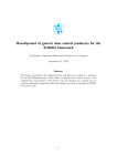
software developed for the LinkQuad in this thesis. A sketch of the different
components and the connections in between them can be seen in Figure 1.2.The
dimensions of the LinkQuad [AB11] can be seen in Figure 1.1.
Existing Control
The existing control, previously mentioned as the inner control loops, consists of
stabilization of attitude and an open loop control of the thrust. The nature of the
dynamics allows pitch, roll, yaw and thrust to be controlled individually.
Each angle is stabilized with a PD controller and the thrust is not controlled but is
forwarded directly to the motors through the mixer, see Figure 1.3.
Each PD controller use the corresponding input from the RC controller as a setpoint
and the angle to be controlled and its corresponding angular velocity as
measurement values. The output is the reduction or increase in thrust that should be
put on each rotor, which is aligned with the angle.
Each controller is then connected to a mixer, which calculates each motor’s control
input. This is done by adding the thrust input to the output from the PD controllers
of yaw and the angle which is parallel to the current motor. As an example, the back
motor’s input is the sum of the output from the thrust control, the output from the
yaw control and the negated output from the pitch control. The output from the pitch
control is negated to have the inverse effect on the back rotor compared to the front
rotor.
Each angle and its angular velocity are derived from an attitude and heading
reference system (AHRS).
(a) Top View
(b) Front View
Figure 1.1: Dimensions of the LinkQuad [AB11]
1.3 Problem Description
Thesis extends the existing system in two ways:
1 User control via a commercial device, i.e. a smartphone or a
R
PlayStation 3gamepad
(PS3 gamepad), will be introduced. the user should
be able to steer the LinkQuad via this device without using the existing RC.
2 The LinkQuad should be able to function as a mobile crane with a slung load.
A slung load is a uniform mass attached with a string to the bottom of the
quadrotor and it is allowed to swing freely.
11
Chapter 1.
Introduction
Figure 1.2: This sketch shows the different components of the LinkBoard and the
known protocols that are used between the components.
SMCU
thrust
CMCU
P
Motor 1
θ , θ̇
AHRS
PD
φ , φ̇
Mixer
ψ , ψ̇
Motor 2
PD
Motor 3
PD
Motor 4
RC
Figure 1.3: The existing control: Setpoints are received from the RC receiver at the
SMCU. The setpoints and the estimated angles from AHRS is sent to the CMCU. At
the CMCU, the controllers’ outputs are calculated, saturated, mixed into individual
PWM outputs and sent to the motors.
The first problem introduces the following subproblems:
• Choice of smartphone platform.
• Communication between the smartphone and the LinkQuad.
• A user friendly interface on the smartphone which enables most of the
functionalities of the RC.
Since smartphones do not support the same radio links as the RC, another method of
communication needs to be found. The Gumstix board on the LinkBoard has access
to a Wifi connection which could be used instead. This implies that the
communication is required to go through the Gumstixs instead of passing through
the existing radio link that the RC use. This can be solved by creating a server
application on the Gumstix which uses the serial communication to forward inputs
and commands.
The second problem introduces oscillations from the slung load and will impair the
12
1.4 Context and Purpose
Figure 1.4: Illustration of the system.
flight capabilities. Therefore, control of the slung load must be introduced to reduce
the pendulum effect of the load. The quadrotor should then be able to lift, fly, hover
and land with a slung load and during the hover be able to reject disturbances, see
Figure 1.4 for a sketch of the system in action.
The second task could not be completed fully, but the following subproblems were
found and completed:
• Control of a slung load in the horizontal plane on an experimental rig.
• Investigation of the existing sensors to get an estimate of the altitude.
• Altitude control.
The control of the slung load could either lie on an external personal computer or in
the server application on the Gumstix board. If the angles of the slung load would be
derived by computer vision algorithms, it would have to lie on an external computer.
However if local sensors could be used, it would be possible to have the solution on
the Gumstix. Since a sensor solution from a present laboration rig is easier to use
and it is available, it will be the first choice.
To apply the solutions to the slung load control and communication device, altitude
control of the LinkQuad is required. This could be provided by the global
positioning system (GPS) but only outdoors.
Due to this and to that the GPS was not fully implemented at the time of the thesis, it
was disregarded but for future solutions it could be used to provide absolute
positioning. Measurements of the altitude could still be derived from a pressure
sensor.
1.4 Context and Purpose
The objective of this report is to investigate the use of commercial devices as user
interfaces on a quadrotor and to investigate solutions to the problem of slung load
13
Chapter 1.
Introduction
control.
The purpose of substituting the RC controller with a commercial smartphone is that
they are more easy to grasp and might therefore be easier to use for a novice than an
RC controller.
The purpose of slung load control is to reduce the oscillations of the slung load and
its effect on the quadrotor’s flight performance, thus enabling it to handle heavier
loads.
ELLIIT is a collaboration between multiple universities within common fields, i.e.
realtime systems and artificial intelligence, and the development of the LinkQuad
quadrotor is one of its projects. This Master’s thesis is a part of the ELLIIT
collaboration.
1.5 Delimitations
The thesis considers only two types of smartphones, those with Android OS or
Apple iOS. It was not relevant to do an evaluation of all smartphone operative
systems, since it was more important that the smartphone fulfilled the requirements
of the thesis and that the development could start early.
The load is considered to be attached or disattached and that no release or
attachment mechanism exists. This implies that no effects of releasing or attaching
the load will be controlled.
1.6 Method
The thesis started with an investigation of what possibilities and challenges it
contained. This was done by using a ”Divide and Conquer” approach where the
thesis was split into smaller subproblems and then a workflow was created from
these subproblems, see Figure 1.5.
When the thesis had been broken down into workable challenges, the development
started. The thesis was done in a more dynamic way by focusing on the most present
and doable problem, instead of having different phases designated for i.e.
development or testing. The planning was therefore done by using a bottom up
traversal of the workflow so that all dependencies would be met before a new task
was initiated.
It was also decided that the two authors should focus on their own area of expertise
even if that was occasionally disregarded and both cooperated to solve a problem.
Even though different areas of focus existed, both students worked to keep an
understanding in each other’s areas. Testing was done together since the LinkQuad
requires both a pilot and an operator of LinkGS.
The tests were designed in different ways depending on what sort of functionality
was to be tested. If it was a pure software function that required no actuation of the
process, the functionality could be tested on the real platforms with the motors
turned off. However, if the function required flying or some other live interaction
with the LinkQuad, it was always simulated first using models or scripts in
MATLAB and then tested on the real quadrotor.
14
1.6
Method
Figure 1.5: Workflow chart.
Documentation have been made continously to ensure that no knowledge was lost
during the development and that the information was as precise as possible.
Distribution of work
Mikael Rudner
Niklas Hansson
Common
Keyboard Controller
Network Protocol
Android Client
Testing
R gamepad
PlayStation 3
Control
Gantry Crane
Simulations
Serial Communication
Server
Computer Client
Low-pass Filter
Table 1.1: The distribution of work between the two Master’s Thesis students.
In the beginning it was planned that Niklas Hansson would focus on the control
problems of the LinkQuad while Mikael Rudner would focus on the programming
problems. However, the dependencies of the subproblems implied that some areas of
focus was intermixed. The distribution of the work can be seen in Table 1.1.
15
Chapter 1.
Introduction
1.7 Related work
The interest in quadrotors has expanded over the latest few years since its simple
design and control makes it an attractive solution for UAVs and, if properly
configured, as radio controlled toys.
The research within steering quadrotors with smartphone is not so extensive but
there are two significant projects, where the first is the commercial AR.drone, which
is steered with either an iPhone or an Android smartphone. It can also be extended
by creating a custom client for a computer and connecting a human interface device
(HID) to the computer for inputs.
An second solution was investigated by Lichtenstern, Angermann and Frassl at
German Aerospace Center (DLR) where an Android smartphone is used to control a
swarm of quadrotors to film outdoor events. [LAF11]
The area of slung loads is host to a wide array of research projects for both large and
small single-rotor helicopters. An example of such a project is the work of Bisgaard,
Bendtsen and la Cour-Harbo, whom has investigated modelling of a slung load
system on a small-scale helicopter. [BBlCH06] As for control of a slung load on
quadrotor, it was not so extensive. Two videos were found from a project at the
Aerospace Controls Laboratory (ACL) at Massachusetts Institue of Technology
(MIT) in which a quadrotor successfully rejected disturbances on a slung load.
However, no official papers or web page could be found.
1.8 Outline of the report
The report is divided into the following chapters. Each chapter contains a number of
sections that are described below.
• Introduction: This chapter presents background information, problem
description, context of the problem, methodology and related work.
• System Overview: This chapter describes the system as a whole, platforms,
the main software of the server, network communication, serial
communication, logging and how tests and verification was executed.
• User Control of a Quadrotor: This chapter describes the solution of the user
control of the LinkQuad.
• Slung Load Control on a Quadrotor This chapter describes the gantry
experiment, sensors, the altitude control and the progress of the control of the
slung load.
• Conclusions: This chapter describes the conclusions of the thesis and
recommendations for future work.
• Appendices: Documents that describe how to use the applications that has
been developed and other aspects that help to set up the system.
16
2. System Overview
This chapter will discuss how the system as a whole is composed and how the
different components interact.
The chapter first presents an overview over the system and then continues to the
platforms of the system and the related development tools. Third, the server design
and its implementation will be introduced. Fourth, the network communication will
be described. The fifth section contains the implementation of the serial
communication between the different microcontroller units. After that, the logging
is presented and finally, the testing and verification of the system will be described.
2.1 Overview
The system can be distributed on three platforms; an arbitrary computer with
support for wireless network and Bluetooth, a Android smartphone with root access
(rooted), which is configured to support ad hoc networks, and the LinkQuad itself.
The computer and the smartphone make up the client side of the system, where
either enables the user to steer the LinkQuad. The LinkQuad hosts a server for a
client on a Gumstix board and a client can connect to it via the ad hoc network. The
R
user will need a PlayStation 3gamepad
(PS3 gamepad) to fly with the application
on the computer, which is connected via Bluetooth and registered as a joystick on
the computer. An illustration of the system can be seen in Figure 2.1.
From here on, the clients will be referred to as Computer Client and Android Client
and the server as Server.
Figure 2.1: Illustration of the system.
17
Chapter 2.
System Overview
2.2 Platforms
Each part of the system, e.g. clients for user control, has to reside on a platform and
the development tools and design choices rely on these platforms’ hardware design.
In this section, the different platforms will be presented and the main focus will be
on the smartphone since the hardware options are diverse but might introduce
restrictions, such as programming language and input possibilities.
Smartphone Client
The Master’s Thesis specification contained the assignment to develop a smartphone
application that could be used to steer the LinkQuad. Some questions existed from
the beginning such as if the target platform should be Android or Iphone.
The Choice between Android and Iphone The first challenge to complete was the
choice between Android smartphones and Iphone with iOS. Both had their
advantages and disadvantages. The initial study of Android and iOS are shown in
Table 2.1.
Android
Java
IPhone
+
Objective C
-
Apple Store
-
Development License
-
Accustomedness
+
Open Source
+
Table 2.1: Initial study of advantages and disadvantages of Android smartphones and
Iphones. Plus sign (+) denotes a positive feature. Minus sign (-) denotes a negative
feature.
Android uses the Java programming language with the Android SDK and to develop
an Android application no licenses are needed. Android itself is also open source
which in the authors experience gives some assurance that it has some degree of
code quality. [Goo11]
To develop for the Iphone, it is required to have a development license and a Mac
computer, where the development license costs 99$ per year. The programming
language for Iphone iOS is Objective C, which is a modified version of C and C++.
When an application has been developed, it has to be added to Apple’s App Store to
able distribution to more Iphones then the one it was developed on. This is required
since Apple does not tolerate unmonitored third party applications and requires all
applications are reviewed by them. This related to public distribution and details
regarding any other options that might be available was not investigated. [App11]
Since Android smartphones were cheaper and that neither of the thesis students had
any experience with Objective C, it was quickly decided that Android was the
preferred choice.
After the development had started, it was noticed that the initial study missed some
important parts, i.e. multitouch. A second study took place and is presented in
Table 2.2.
18
2.2 Platforms
Android
IPhone
Java
+
Open Source
+
Accustomedness
+
-
Multitouch
-
+
Ad Hoc
-
+
Reliability
+
Objective C
-
App Store
-
Development License
-
Different Platforms
-
Table 2.2: Secondary Study of pros and cons. Plus sign (+) denotes a positive feature.
Minus sign (-) denotes a negative feature.
Iphone has a more accurate multitouch than Android smartphones, which has less
accurate multitouch. This was noticed during the development of the joystick for the
Android application. A second problem for Android is the hardware dependecy and
the open source customability. Manufacturers may develop different
implementations of the Android which may require porting of software. Since the
different manufactures are using their own hardware, it may result in that a Android
smartphone does not fullfil the hardware requirements.
Iphone smartphones are on the other hand restricted and they have all the similar
hardware and are therefore more reliable. The Iphone, compared to the Android
smartphone, also supported ad hoc networks which is a crucial feature since the
Gumstix boards on the LinkQuad had no DHCP server configured in its present
version. These problems limits the possibilities of which platforms can be used for
an Android client.
Android was still considered to be the best choice, since the ad hoc network problem
could be solved by changing the wpa_supplicant, the network software client, and
since lack of multitouch was not a major drawback.
The problem of different platform specifications still remains and this system was
tested on a LG P500 Optimus One, from here on referenced to as the test phone or
the test platform.
Multitouch or Singletouch When the development first started, it was planned to
use the inertial measurement unit (IMU) to set pitch and roll and to use a virtual
joystick to set thrust or altitude and yaw setpoints simultaneously.
The virtual joystick and a button to activate the capturing of IMU values were first
implemented using the multitouch ability of the test phone. The multitouch would
enable the simultaneous use of the IMU and the virtual joystick, but its performance
was poor.
The specific implementation of multitouch mixes up the finger inputs and
sometimes even loses track of a finger. This was unacceptable since the application
could then send wrong control values, resulting in a crash. Multitouch was therefore
19
Chapter 2.
System Overview
considered to be inadequate and a singletouch approach was used instead implying
that thrust and yaw could not be controlled in parallel with pitch and roll.
Ad Hoc Network One of the bigger challenges was that the Android smartphone
did not support connections to ad hoc network. An initial assumption was that it
could be avoided by configuring the Gumstix board to act as an DHCP server for the
network it created but its operative system did not have support for it. The solution
to the problem was found by using a rooted Android smartphone and a rebuilt
wpa_supplicant file. [bla10]
The guide contained a prebuild on the wpa_supplicant, which changes the network
filter’s behavior to show and accept ad hoc networks. An ad hoc network is shown in
the same place as other networks but has a prefix of an asterisk (*).
Threads After the initial study of smartphones, one of the arguments for using
Android was the Java programming language, which the students has experienced
with. However, the Android SDK had made some changes which led to a more
challenging development than was expected. The challenges and their solutions are
listed below:
An Android application consists mainly of activities which are executed as the user
interact with the screen. This is not suffice since the application will have to maintain
a constant network connection and read continously from the IMU. It should thereby
not be possible to have the application running when the smartphone is sleeping or
the application is not in focus. This could be solved by extending the application
with either a Java service or a Java thread to handle these tasks in the background. It
was decided to use the latter since it was considered to be easier to implement.
The challenge of closing the thread and exiting the application on lost focus was
solved by killing the application as soon as the actitivy, which the thread belonged
to, was paused or exited.
Together with a non-blocking read operation in the network connection, it could be
said that the Android Client is a single-threaded application with activities attached
to it.
Computer Client
The Computer Client application will reside on computer systems and since C++
was chosen as one of the programming languages for the thesis, see below, the
problem of machine and operative system dependencies came forth. For example, a
Windows machine does not support Posix threads (pthreads) per default and *nix
systems does not support Windows threads.
The thesis students had access to computers with Windows, Unix and OS X as
operative systems so it was decided that the applications should be portable to all
three operative systems. This could be achieved by using the Boost C++ libraries
that are portable to all of the operative systems in question. Boost supports
everything from threads and math to network communication and file handling,
which makes it ideal to use in a multiplatform application. [BD11]
20
2.3 Server
Server
Since the Server is supposed to be executed exclusively on the Ångström based
Linux distribution, it was decided to use the standard C++ libraries.
Development Tools
The main issue was the decision of which language to implement Server and
Computer Client in. There was a probability in the beginning that the Computer
Client would be integrated into the LinkGS. Thereby, the same programming
language, C++, was chosen for Computer Client.
Since Server was to be put on the Gumstix board without any dependices, the list of
possible languages was longer. However, since the Gumstix board uses the
Ångström operative system, which supports gcc, and the Computer Client was to be
implemented in C++, the choice fell upon C++ for the Server as well.
Since the smartphone was based on Android, it was to be developed in Java.
MATLAB was used together with Simulink to derive and simulate different control
and filter algorithms.
2.3 Server
In this section the general implementation of the Server and design patterns will be
discussed. Detailed implementations of specific parts of the Server are discussed in
the following sections; Serial Communication (Section 2.5), Network
Communication (Section 2.4), Sensors (Section 4.2), Control (Section 4.3) and
Logging (Section 2.6).
The Server consists of three major parts; Master, Connection and
SerialCommunicator. Master and its implementations contain a state machine
and a control loop. Connection and its implementations handle the network
communication. SerialCommunicator consists of two parts, an interface of
functions for Master to use for the serial communication with the Control MCU
(CMCU) and the second part is a thread which handles the serial communication
with Sensor MCU (SMCU). Several patterns were used to structure and implement
the Server, both to lower the code complexity and to make it easier to modify in the
future.
Master, Connection and SerialCommunicator are separated with either a
monitor or a mailbox to ensure mutual exclusion on shared data.
The heart of the Server is the abstract class Master and its two implementations,
LoadedMaster and FreeMaster, that are two different state machines whose
behaviour depend on whether a load is attached or not. The state machine
functionality exists in Master where the current state is periodically invoked and the
specific state’s behaviour is defined and executed in the implementing class.
The current state is kept in ReferenceMonitor and state transitions can be made
from either Master or Connection. This enables a transition to be triggered by
commands from the network communication and thereby the user. The state
machines and the control are discussed further in Section 4.3.
The Master classes’ communicate with Connection through two mediators,
MailBox and ReferenceMonitor, which were created using the Mediator
21
Chapter 2.
System Overview
Figure 2.2: The class diagram of the Server. The Connection are implemented according to the Template Method pattern. The MailBox, ReferenceMonitor and
SensorMonitor are implemented according to the Mediator pattern.
pattern.[Gam96, p.273-p.282] Mailbox can contain a message that should be sent to
the connected client and ReferenceMonitor holds the current state and the
setpoints of the control loop. The Mediator pattern implies that the Master classes
need only to know that the message is only required to be put in MailBox to be sent.
In the same way, it implies that the Master classes are only required to use
ReferenceMonitor to get current setpoints. Both MailBox and
ReferenceMonitor act as mediators, limiting the interaction between the two
classes, thus making the two parties implementation independent of each other and
easier to modify. Both MailBox and ReferenceMonitor have mutual exclusive
entry to all functions to ensure thread safety.
The network implementation for the Server were implemented using the behavioral
design pattern Template Method. The Template Method pattern allows a superclass
Connection set a template of execution and deferring some steps to subclasses to
implement.[Gam96] This enables future users to extend with their specific
implementations of network communication. For further details, see Section 2.4.
SerialCommunicator consists of two parts, an interface for sending data to the
CMCU and a thread which handles all communication with the CMCU. This is to
enable fast access for the Master classes to send data and to reduce the
computational delay for the control loop by removing the responsibility of receiving
data.
The thread of SerialCommunicator is separated from Master with
SensorMonitor. SensorMonitor is also implemented according to the Mediator
pattern and is protected by mutual exclusion. Its main purpose is to supply the
Master classes with the latest available sensor data. SerialCommunicator is
thread-safe since all shared data is protected in SensorMonitor and the interface to
CMCU does not share any data with the thread in SerialCommunicator.
22
2.4
Network Communication
2.4 Network Communication
The clients need a uniform way to communicate with Server as they are
implemented on different platforms. Their inputs need to be forwarded to the Server
and interpreted without consideration of which client the inputs originate from. A
protocol was therefore developed for the communication between the clients and the
control loop in the Server, see Section 2.4 for a detailed description of the protocol.
Messages are packed according to this protocol and then sent to Server via a
transmission control protocol (TCP) or user datagram protocol (UDP) connection.
The choice of underlying protocols is also motivated in this section.
As can be seen in Figure 2.3, the clients handle the communication with TCP/UDP
directly while Server separates the network responsibility from the control loop with
Connection to reduce the computational delay in the control loop. Connection is a
network handler, which is in charge of the network communication of a current
connection. It interprets all received messages into setpoints or into commands and
feed them to the control loop via a ReferenceMonitor. All outgoing messages
from the control loop are put in a mailbox, which Connection pulls from and sends
to the other party. For details, see page 24.
Figure 2.3: Illustration of active network communication between Computer
Client and the control loop in Server. MB stands for MailBox and RM for
ReferenceMonitor.
Network Protocol
First, the design of the internal protocol is described and then the implementations
of the TCP and UDP versions will be introduced. A summary of the different
messages is given in Table 2.3.
When a message is to be sent, it is packed into a 160 bits large package with the first
32 bits as the ID and the following 128 bits as the payload. In the beginning of the
thesis a version with 8 bits ID and 32 bits of payload was used, but this resulted in a
constraint on the payload. The constraint was that a direction message had only a
range of -127 to 128, which was sufficient for the current problem but was an
unnecessary restraint for future usage. The Gumstix board has support for the IEEE
802.11b/g standard for wireless networks, [Mei11] implying a possible connection
speed of 54 Mbit/s, this would result in that a 40 bit message sent over a TCP
23
Chapter 2.
System Overview
Message Type
Message ID
Payload
Ping
0
Acknowledge
Direction Message
1
Pitch, Roll, Yaw, Thrust Difference
Trim Message
2
Trim Value
Land/Lift Message
3
Acknowledge
Terminate Message
4
Acknowledge
Close Message
5
Acknowledge
Table 2.3: Different network messages with their ID number and how the paylod is
interpreted.
connection (52 bytes head) will result in a 57 bytes package. [Dyk03] This package
would be sent in 8, 44 · 10−6 s in a ideal situation with direct line of sight and no
interference. Since the control loop has a sample time of 10 ms, this implies that
1184 different messages can be received during one period. For the 160 bit message
sent over a TCP connection (52 bytes head) would result in a 72 bytes package and
the package would be sent in 1.07 · 10−6 s. This would enable 937 different
messages to be received during one period of control. Since receiving only one
message in a loop of the control is sufficient, the limitation of using eight bits is
unnecessary and would perhaps constrain the accuracy for future extensions.
The data of the payload is representing different properties depending of the
message type. For a command message, type 0 and 2 through 5, the first 32 bits of
the payload is either 1 or 0 to determine whether it is a command or an
acknowledgment to a previous command message. For a direction message, the
payload consists of four integers representing setpoints for pitch, roll, yaw and
difference of thrust. The setpoints of pitch, roll and yaw are to be sent to the inner
loops of attitude control and the setpoint difference of thrust is to interpreted either
as how much the thrust setpoint should change (manual flight) or how much the
altitude setpoint should change (altitude control).
TCP and UDP
The main advantage of using TCP is that the system gains a reliability of
communication but also a disadvantage of slower communication. During the
testing it was noticed that the disadvantage was so small that it was not noteworthy.
However, this reliability is not always a requirement. When a client is sending a
direction message, the Server requires only the latest input and it does not matter if
occasional messages are lost during the flight.
The main advantage of using UDP for realizing the network protocol is a fast
communication but at a loss of reliability since packages may be lost. During
testing, it was found that the loss of packages happens more often the further apart
the reciever and the transmitter where.
Both protocols are implemented in two versions of Connection, TCPConnection
and UDPConnection.
Network Handlers
Server uses a dedicated network handler, Connection, to separate the main
functionality from the network communication. The purpose of this is to reduce the
24
2.5 Serial Communication
computational delay of the main functionality, i.e. the control loop in Server and
increase the stability of the system. A second benefit of this is the abstraction level
between the network implementation and the main implementation, which implies
understandability and usability.
An instance of the network handler is created when a client tries to connect to
Server and there is a limit of one active instance to ensure that only one client can
steer the LinkQuad simultaneously. The network handler executes a simple loop,
which reads from the connection if data is available and after that it writes to the
connection if there is a message to send available. The incoming messages are
interpreted into setpoints and commands, which are forwarded to the
ReferenceMonitor, which supplies the control loop with setpoints and its current
state and the outgoing messages are fetched from MailBox.
Mailbox
A mailbox stores a single message that has been received or that should be sent. It
can only store one message at a time but it prioritizes what messages that should be
stored by looking at the id of the message. The greater the id number, the higher
priority, e.g. if a Ping Message, id = 0, is stored in the mailbox, a Land/Lift
Message, id = 4, will overwrite it.
However, if the new message is of the same type as the stored message, the new
message will always overwrite the stored one. This is to ensure that the latest data is
used at all times.
Reference Monitor
The reference monitor stores the latest set points and the current state that the
control loop should use. An example of such setpoints are the desired attitude of the
LinkQuad.
2.5 Serial Communication
The LinkQuad has an existing interface for serial communication to and from the
SMCU and the CMCU, which enables applications on the Gumstix boards to access
sensor data and send data to be used in the existing control loops. The interface
supplies the user with both an existing protocol and functions to import and export
data to the protocol. This section will therefore only introduce the reader to this high
level protocol and its uses but will omit how it was implemented on the serial bus.
From an example given by the developers of the LinkBoard, a simple serial
communication layer was implemented, which is used to send data to the CMCU.
The same example was also used to implement a listener to the serial communication
and thereby separating the control loop from the serial communication with a
monitor. Both these parts exist in SerialCommunicator, see Figure 2.4.
SerialCommunicator is both a thread, which handles the incoming data from
SMCU, and a set of functions for sending data to CMCU. This enables the control
loop to send data direct to CMCU and to not waste execution time to read from
SMCU.
The low-pass filter is executed in SerialCommunicator due to the need of a
different sample time than the control loop. The SMCU can send data at a maximum
25
Chapter 2.
System Overview
frequency of 500 Hz and is currently sending at 250Hz to SerialCommunicator.
This is implied by the need of a high sample rate of the low-pass filter of the
pressure sensor, see Section 4.2. SerialCommunicator puts the sensor values in
SensorMonitor, which is shared with the control loop.
Figure 2.4: Illustration of serial communication between the control loop and the
external microcontrollers. SM stands for SensorMonitor and SerialComm stands
for SerialCommunicator.
Serial Protocol to Control Microcontroller Unit
The existing high level protocol supports arbitrary data to be sent to the CMCU
packed in an array with eight floats. This can be used in the CMCU by configuring
the PID loops in LinkGS to apply receivedParamsX, where X stands for the index in
the float array, as a target or an input. The array is also logged and available for
plotting during runtime in LinkGS.
In Table 2.4, the present use of the parameters is presented.
Index
Data
0
1
2
3
4
5
6
7
Pitch.
Roll.
Yaw.
Yaw trim.
Set point for the altitude control.
Control signal.
Current state or PID output if manual tracking is live.
Altitude.
Table 2.4: Received parameters and their contents ordered after index. The parameters are sent from the Server to the Control MCU through a serial connection.
26
2.6 Logging
Serial Protocol to and from Sensor Microcontroller Unit
The SMCU can supply the other microcontroller units (MCUs) with data on the
serial bus. To gain access of this data a request must is sent of what sensor values
that are wanted and how often these values should be sent. The request is an array
which contains the identification numbers of the sensor values that are wanted. The
identification numbers can be found in [AB11].
The SMCU can send at a maximum frequency of 500 Hz and at present time the
Server uses a frequency of 250 Hz to run filters on the data at a high frequency.
There is no need to push the SMCU after the request, the sending of data starts at
once. The data is unpacked into a struct and there easily accessed for further use.
Serial Listener
The serial listener handles the responsibility of the high frequency communication
from the SMCU, applying a low-pass filter to the noisy pressure signal and
supplying the sensor monitor with the latest data.
The low-pass filter is put here to decrease the computational delay of the control and
to allow it to have a higher sample frequency than the control loop, for more details
see Section 4.2.
SensorMonitor
The SensorMonitor is implemented in the same way as the reference monitor but
holds sensor values instead of state and position changes. It has mutual exclusive
entry to all functions to ensure thread safety.
2.6 Logging
All of the developed applications have support of logging. The Android Client uses
adb logcat for logging and debugging. The Computer Client and the Server use
custom logging procedures, Printer and FileLogger. The logging procedures can
be configured with the configuration file for the Computer Client and the Server.
Printer
Printer prints the log messages to the screen. This enables the user to follow the
execution live on the screen.
FileLogger
FileLogger prints the log messages to a file, whose name is set in the configuration
file.
2.7 Testing and Verification
This section will give an introduction to how the different functions of the system
were tested and their functionalities verified.
The foundation of the system is the network communication so it was to be verified
first. The protocol of network communication and the applications that use the
protocol had been implemented in different languages so it was chosen to use a
27
Chapter 2.
System Overview
Figure 2.5: The different components of the system that was tested.
black-box technique called black-box random testing.[Bur03] The client sends a
message, the server unpacks the message, then repacks it again and sends it back to
the client. At the client, the received message could then be verified to be the same
as the sent message.
It was important that every message type was tested with both normal values and
values that are outside of the limits of the payload and that messages with incorrect
identification numbers are tested so it is proven that they are rejected without
problems. See Section 2.4 for more information about the payload. It can then be
proven that the network communication can handle all of the different types of
values and messages. The test set is required to be executed for both the TCP and
the UDP protocols. The test set is presented in Table 2.5.
Since the development environment on the computer was equipped with debugger
tools, it enabled the use of the white box technique coverage analysis. It implies that
the execution of the code is studied and how inputs affects its flow. The goal is to
verify that all code statements executes in a proper way. It is called coverage
analysis since a complete coverage requires that all code statements are tested. If
not, a code inspection must be done to design test cases which will maximize the
coverage. Together with a black box technique boundary value analysis, a good set
of tests could be created. The input for the tests was different messages sent from
the network connection, see 2.4. The output was written to the logger and
studied.[Bur03, p.72, p.101]
As for the computer client’s functionality, the focus was put upon the human
interface devices (HIDs). The test set was first executed by using the keyboard to
28
2.7 Testing and Verification
Test number
Input
Expected output
Network-1
Network-2
Network-3
Network-4
Network-5
Network-6
Network-7
Network-8
Network-9
Network-10
Network-11
Network-12
Network-13
Direction with invalid pitch value
Direction with invalid roll value
Direction with invalid altitude value
Direction with invalid yaw value
Direction with normal payload
Lift
Terminate
Close
Trim Right
Trim Left
Ping
Incorrect Negative Message ID
Incorrect Positive Message ID
Error
Error
Error
Error
Input
Input
Input
Input
Input
Input
Input
Error
Error
Table 2.5: The test set of the network communication - Input is messages sent from
the client computer, Expected output is the message that is sent back from the server.
create messages and then repeated for the PS3 gamepad. The test set can be seen in
the Table 2.6.
Test number
Input
Expected output
Computer-1
Computer-2
Computer-3
Computer-4
Computer-5
Computer-6
Computer-7
Computer-8
Computer-9
Computer-10
Computer-11
Computer-12
Direction
Lift, Direction
Lift, Direction, Land
Terminate
Close
Lift, Direction, Terminate
Lift, Direction, Close
Trim Right
Trim Left
Lift, Direction, Trim Left
Lift, Direction, Trim Right
Ping
No output, No lift off yet
Lift off, Flight
Lift off, Flight, Landing
Termination message
Closing message
Lift off, Flight, Emergency landing
Lift off, Flight, Emergency landing
Trim
Trim
Lift off, Flight, Trim
Lift off, Flight, Trim
Ping
Table 2.6: The test set of the computer client - Input is the action that the user introduces. Expected output is the log of the client.
For the Computer Client, it was also important that the tests were done for the Unix,
Mac and Windows platforms to ensure portability.
The tests on the Android Client were done by using the same test techniques and test
set, Table 2.6, as the Computer Client.
In comparison with the personal computer environment it was more challenging to
monitor the execution of the server program since the Server is executed on the
29
Chapter 2.
System Overview
Ångström distribution on the Gumstix board. Because of this the black box
technique equivalence classes partitioning was used. By letting each message being
an equivalence class and creating a single test for each equivalence class, the test set
can be seen in the Table 2.7. [Bur03, p.67]
Test number
Input
Expected output
LQServer-1
LQServer-2
LQServer-3
LQServer-4
LQServer-5
LQServer-6
LQServer-7
Direction
Lift
Terminate
Close
Trim Right
Trim Left
Ping
Server parameters
Beginning to send values (hover)
Emergency land, end sending values
Emergency land, close existing connections
Adding value to the yaw
Adding value to the yaw
Ping in logger and ping back
Table 2.7: The test set of the LinkQuadServer - Input is the message sent from client,
Expected output is written to the server log.
After each component or group of components had been tested, an integration test
was designed to ensure reliability when combining the different components. This
was done by first executing all the the different tests again but on the whole system
and complementing by doing several field tests (Chapter 5).
30
3. User Control of a Quadrotor
This chapter will discuss the investigation and implementation of the clients, which
allow the user to control the LinkQuad.
The user control problem originates from the need of controlling the LinkQuad
without radio control (RC). Smartphones are not supplied with the same radio link
capabilities as the RC so other channels of communication were required. This was
solved by having a server on the Gumstix, which was connected to the Control
MCU (CMCU) through a serial connection and to the clients through a wireless
connection.
A client on a computer was first developed to be able to debug the network
communication and the server with a keyboard. A second client on a Android
smartphone was developed to steer the LinkQuad. The Android Client uses its
inertial measurement unit (IMU) and a virtual joystick to control the attitude and the
altitude of the LinkQuad. During the development of the Android Client, another
human interface device (HID) was integrated into the Computer Client, namely a
R
PlayStation 3gamepad
(PS3 gamepad).
This chapter will first present the investigation of the target smartphone platform
and then the implementation, design and evaluation of the smartphone client.
Finally, the Computer Client will be presented.
3.1 Android Client
The Android Client is the main application for steering the LinkQuad. The
advantage of using the Android Client is that it provides an interface that is naturally
mapped to the process, by using the IMU of the smartphone to steer, and a graphical
interface that is naturally mapped to cultural standards and the RC
controller.[Nor02, p.23]
A disadvantage is that the implementation of the virtual joystick, which set the
setpoint for the altitude or the thrust, does not give the same feeling of control as the
PS3 gamepad or the RC controller. This is due to the lack of physical feedback.
Another disadvantage is that Android smartphones usually have different hardware
configurations, which may lead to bad performance, see Section 2.2.
The Android Client requires a rooted and properly configured Android smartphone
to connect to an ad hoc network. It does not support multitouch even if the
functionality exists in the code. This is purely in case of a better implementation of
multitouch being developed for the Android smartphones, see Section 2.2. For more
information about how to use the Android Client, see Appendix B.1.
This section will first discuss what kind of users that might use this application and
what ramifications this will have for the design and implementation. Finally, the
design of the different interfaces will be discussed.
31
Chapter 3.
User Control of a Quadrotor
3.2 Users and Environment
Flying the LinkQuad is not an easy task for an novice pilot and it would be even
harder if the steering interface was poorly designed or implemented. Thus, it is
important to know in which situations the interface will be used, which possible
users exists and what their needs are for the application are. The following
assumptions are made from the Department of Automatic Control at LTH.
The most likely user is a graduate student that uses the work of this thesis for his or
hers thesis. He or she will probably have a strong knowledge base in embedded
systems, computers and control but will not have used a quadrotor before. It is also
possible that an experienced quadrotor pilot will try to use the Android Client when
he or she acts as a test pilot. The least probable user is an ordinary person with
nearly no experience of using the LinkQuad. In the Table 3.1, the three different
types of users and theirs different sets of knowledge are displayed; the graduate, the
experienced pilot and the ordinary person.
Type Name
Important knowledge and skills
Probability
Graduate
Quadrotor Experienced Pilot
Ordinary Person
Embedded systems and control
Quadrotors and RC
None
High
Low
Low
Table 3.1: The possible users of the user control of the quadrotor, their possible
knowledge and the probability of that they will use it.
The graduate will use the Android Client in his own research and would want to
have an application that is easy to understand and use but most important, easy to
modify. The quadrotor experienced pilot will use the Android Client to do test
flights or to get a new flight experience. The ordinary person is probably a friend of
the graduate or to the quadrotor experienced pilot who wants to try the LinkQuad.
From this set of users, it can easily be seen that the most probable user will have
some but not an extensive knowledge of flying quadrotors.
This implies that the steering and the graphical interface should be as natural as
possible so that a user with little knowledge of quadrotors can understand what the
different controls are used for. It should also be in focus that the steering should be
reminiscent of the steering interface of the RC. Since if one of the users has used a
RC controller before, the introduction would be easier.
The application is not meant to be accessible for the public. Its main purpose is to be
used for development and research. Therefore, the focus will also lie on making the
software easy to modify and maintain.
32
3.3 Design of the Interface
3.3 Design of the Interface
Figure 3.1: The action cycle starts by the user having a goal. The user will then
execute a set of actions needed to perfom the goal. Then the user will perform an
evaluation that the actions that has been done indeed fulfill the goal.
A human action has two aspects, execution and evaluation. The execution aspect
involves the doing of something and the evaluation is the comparison of what
happened with what was expected to happen (the goal). The user starts by setting a
goal. The goal is then translated into an intention to do some action. The action is
translated into a set of internal commands, an action sequence, that is executed upon
the world. After the execution aspect has been performed the evaluation aspect
starts. It starts with the human that performed the action using his or hers perception
on the world. This perception must then be interpreted to his or hers expectations.
Then compared (evaluated) against the intentions and the goal. Figure 3.1 describes
the cycle of execution and evaluation of a users actions, the so called seven stages.
[Nor02, p.45-p.51]
The seven stages can be a valuable design aid, becuase it provides a basic checklist
of questions to ask to ensure that the gulfs of evaluation and execution are bridged.
The checklist and the answers can be seen in Table 3.2. [Nor02, p.52-p.53]
The question were used to design the user interface by ensuring that the user can see
what action he or she needs to perfom to reach the their goal. This was achieved by
answering the seven questions for each interface. They were also used to ensure that
the user gets the necessary feedback to ensure the user that the action that was
performed indeed did fulfilled the goal of the user.
33
Questions
Menu Interface
Connections Settings Interface
Steering Interface
How easily can one determine
the function of the device?
This question was solved by adding
Menu item names that were self explaining. For an example Connection Settings handles the information needed for the Steering activity
to connect to the Server.
The item from the Menu, which is
the only road to travel to this activity, has a clear and understandable
name that describes what the task is
in this activity.
The item from the Menu, which is
the only road to travel to this activity, have a good explaining name
that describes what the task is in
this activity. The task contains many
normal controls that are quite describing for this application giving
a good hint of what it is used for.
How easily can one tell what actions are possible?
The names of the Menu items explain what can be done.
By having describing labels above
the field and in the toggle button it is
quite simple to see the three actions
that can be made. Write in the ipaddress, toggle the communication
protocol and also checking the local address of the network that the
smartphone is connected to.
Every button has text bound to it
that describes its functionality, but it
is not as easy to determine what the
green button or the joystick is used
for. No labels could be added due
to lack of space. This was solved by
describing it’s functionality in the
manual.
How easily can one determine
the mapping from intention to
physical movement?
This is more an Android question.
By choosing understandable names
as Menu items Android provides the
solution of just touching the Menu
item to travel through them.
This is more an Android question.
By choosing understandable names
the Android provides the solution
of just touching the field or button
to interact with them and the labels
gives a good hint of what task the
item solves.
It is easy to understand what the
buttons do due to the labels but
again the green button and joystick
are the hardest to map. This is easiest solved by testing against the
LinkGS.
How easily can one tell what
state the system is in?
The menu activity only has one
state, either the user is in the menu
or the user already has clicked on a
menu item and navigated to a new
activity.
The are two states that are important
to know. First, if the smartphone
is connected to the LinkQuad network. Second, the different states
of the connection settings. The connection settings can be seen in the
ip-adress field and the toggle button
that is used to change the connection settings.
This is easily verified because of the
feedback log that always print the
values of the controls and what the
Android Client does.
34
Chapter 3.
User Control of a Quadrotor
Table 3.2: Using the seven stages to ask design questions. (page 1 of 2)
Table 3.3: Using the seven stages to ask design questions. (page 2 of 2)
Menu Interface
Connections Settings Interface
Steering Interface
How easily can one perform the
action?
If a user wants to change the connection settings he or she only
needs to touch the menu item Connection Settings and he or she will
navigate to the Connection Settings
activity. Touch screen and understandable names provide quick and
easy navigation.
When the user has navigated from
the menu to the Connection Settings, he or she needs to touch the
ip-address field and fill in the ip and
then choose which protocol he or
she wants to use. This and checking that the smartphone is connected. Then confirming by touching the ok button is the only things
he or she needs to do to perform
this task. Consequently maximum
of four touch actions, two touch actions, one write action and one inspect action are needed to perform
the whole task.
First the right connection settings
need to be set, this can be as much
as four different actions or zero
actions if it is already configured
correctly. Then in the menu navigate through the launch button to
the steering activity. Then the user
is free to steer the LinkQuad directly by natural mapped controls
and an automatic altitude control.
This gives that the user at maximum
needs to perform five actions, minimum one action, to be able to steer
the LinkQuad.
How easily can one tell if the
system is in the desired state?
The menu itself has no purpose besides being a hub for navigation.
Therefore the menu only has one
state that can be seen by checking
if the menu is shown.
The are two states that are important
to know. First, if the smartphone
is connected to the LinkQuad network. Second, the different states
of the connection settings. The connection settings can be seen in the
ip-adress field and the toggle button
that is used to change the connection settings.
This is easily verified because of the
feedback log that always print the
values of the controls and what the
Android Client does.
How easily can one determine
mapping from system state to interpretation?
By clicking on a menu item the user
travels directly to that menu items
corresponding activity.
Easiest checked by saving some settings and test to connect.
This is easily verified because of the
feedback log that always print the
values of the controls and what the
Android Client does.
3.3 Design of the Interface
35
Questions
Question
The German exchange student
Swedish Master’s thesis student 1
Swedish Master’s thesis student 2
How easy can you see the functionalities of the controls?
It seems pretty intuitive. I think I
could use it after a couple of seconds.
Not really familiar with the UDP
and TCP option.
Very easy. Nice, large icons.
Is the joystick easy to use or does
it contain any faults?
In upwards downwards direction
the joystick feels a litle too digital
in comparison to an analog one.
The joystick control was a bit tricky
if you compare to an analog one.
Works nice. Hard to really know
how it works since you can’t actually feel what you are doing.
After getting an fast introduction
to the application, how would
you connect to the LinkQuad?
Using Connection Settings enter the
correct IP-Adress then press Ok, after that press Launch.
Connection settings, enter IPnumber and choose protocol and
after that press launch.
Enter connection settings and enter the IP address, then choose the
proctocol and then press launch.
After that, how would you steer
the LinkQuad?
By tilting the phone and using the
joystick.
First press lift to take off and then
press toogle button and tilt to steer.
Use the joystick to go up or down or
turn.
You control the altitude and yaw
with the joystick and the pitch and
roll angles by tilting the phone
while pressing the accelerometer
button.
Would you say that the application is user friendly?
Yes
Yes
Yes, I think so but haven’t tried it
that much.
36
Chapter 3.
User Control of a Quadrotor
Table 3.4: The evaluation performed by asking three students at the Lunds University five simple questions.
3.3 Design of the Interface
The Seven Principles were used to break down complex tasks into more simple ones
and to design an interface where the user can execute tasks and actions intuitively.
These principles were used to decide what actions that the user should be able to do
and how the actions should be mapped to the controls. [Nor02, p.188]
The Seven Principles (for transforming difficult tasks into simple ones)
• Use both knowledge in the world and knowledge in the head.
• Simplify the structure of tasks.
• Make things visible: bridge the Gulfs of Execution and Evaluation.
• Get the mappings right.
• Exploit the poser of constraints, both natural and artificial.
• Design for error.
• When all else fails, standardize.
From the investigation of the users, it was found that it was important to have a
naturally mapped application, whose functionalities are reminiscent of those of the
RC controller. The design and positioning of the controls were therefore taken forth
by using natural mapping principles. [Nor02, p.23-p.27]
The questions and principles were complemented by an evaluation that was
performed by asking three students at Lund University, that had not used the
application before, five simple questions about the design. The questions and the
answers can be seen in Table 3.4. All of the three students were graduate students
with knowledge in embedded systems and control but with no prior experience with
quadrotors.
By using the seven design questions, the seven principles, natural mapping
principles and the evaluation the following design decisions were made.
Input
Orientation
Set point
Green button + tilt
Green button + tilt
Joystick
Joystick
Trim Right
Trim Left
Land or Lift
Terminate
North-South
East-West
North-South
East-West
-
Pitch.
Roll.
Add/subtract altitude.
Yaw.
Yaw trim right.
Yaw trim left.
Land/Lift.
Terminate.
Table 3.5: Mapping of controls on the Android Client.
When designing the mappings of the controls (Table 3.5) it was important that it
would be an easy task to execute the controls as well to understand what they do.
This is the reason why the seven principles were used to choose how the mapping
should be done. Because of the criteria that the controls should be naturally mapped,
which in general is a very good idea to do anyway, the focus was on designing these
natural maps by the principle of design for errors. The reason of focusing on the
designing for errors principle can be seen in the tilting task. If the user did not have
37
Chapter 3.
User Control of a Quadrotor
to press down a button while using the IMU to steer the LinkQuad, it could result in
disaster because of tilting that is not meant for the LinkQuad, such as failing to close
the application and then putting the smartphone into the pocket.
By using error design and natural mapping the different tasks could be made as
simple as possible without losing any safety and in the same time fulfilling the seven
principles. The simplification of the tasks is that each task has one unique mapping
short of the Land or Lift map. Since of space issues in the graphical interface led to
that they had to share the same button.
Figure 3.2: The menu interface - The menu view of the Android Client.
When the user uses the Android Client he or she always has a goal and the menu is
just the road to that goal. Therefore, it is important that the menu is effective to use.
This is the same problem as the seven principles, breaking a complex task into
simple ones.
To be able to connect to the LinkQuad some connection details are needed such as
the ip-address and what network protocol is going to be used, user datagram
protocol (UDP) or transmission control protocol (TCP). It could always be solved
by prompting when the Launch button is pressed, but that would be unnecessary
because usually that information is the same all the time. This was solved by adding
the menu item Connection Settings which stores the information so it can be reused
when connecting. The two other menu items are the Launch which connect to the
LinkQuad and start the steering and the last are quite self explanatory. The
evaluation, Table 3.4, and the seven questions, Table 3.2, shows that keeping the
menu small was a good choice because it is only the road to the action that the user
wants to perform. The menu interface that was designed can be seen in Figure 3.2.
Regarding the design of the menu interface the Connection Settings interface has
one task with two important settings that it needs to store: the ip-address and the
communication protocol. The easiest way to break down this task is to have one
field with an artificial constraint of only accepting valid ip-addresses to store. The
other setting is what network protocol that should be used. This is solved by using a
toggle button to toggle between the TCP and UDP options, having TCP as default
because it is the safest protocol.
This and by adding utility labels that describe the button and the ip-address field
makes it easy to understand what the task is and where to do it. Another feature is
38
3.3 Design of the Interface
Figure 3.3: The Connection Settings interface - This view takes care of the connection
settings.
that the Connection Settings interface should give the user feedback if the
smartphone is connected to the network and what local address it obtained. Having
no local address is the same as the smartphone not being connected to the
LinkQuad. This so that the gulf of execution and evaluation are bridged. The
answers in Tables 3.2 and 3.4 shows that this was indeed the case. By storing the
data between sessions it is also ensured that this task is not always necessary. The
Connection Settings interface that was design can be seen in Figure 3.3.
Figure 3.4: The Steering interface - In this view all the action regarding the flight of
the LinkQuad is made.
While enabling the steering of the LinkQuad with the Android Client in a way that
is reminiscent of how the RC is used, several functions that the user should be able
to perform were created. The user should be able to change both the attitude and the
altitude of the LinkQuad. These functions would enable the Android Client to steer
the LinkQuad. Some more functions were added to enable termination of the Server
and automated lift and land functions.
By using the mapping of controls, see Table 3.5, a natural mapping is retrieved using
39
Chapter 3.
User Control of a Quadrotor
the IMU, buttons and a virtual joystick. The terminate button was decided to be red
with white text because of using a standard solution of mapping dangerous actions
gives a good impression of that pressing the terminate might not be a safe action.
The trim buttons were placed with the trim right button on the right side and the trim
left button on the left side. In order to use a natural mapping of the trimming of the
yaw. The green button that is used to activate the IMU readings of the pitch and roll
values was placed on the right side to be easily pressed by the thumb while the rest
of the hand holds the smartphone.
It was chosen to have the button in a green color because the color is used in traffic
lighting when the users should start walking. This indicates to the user that pressing
the button is probably going to start something, like in this case the reading of the
pitch and roll values from the IMU. Since the green button is positioned to the right,
the joystick is put on the opposite side to allow use with the other thumb. The
evaluation, Table 3.4, shows, however, that the choice of using a joystick has its
disadvantages. The seven questions can be used to solve these problems, see Table
3.2
All of the three students thought it was hard to get the feeling of the position of the
joystick when they used it. Since that a virtual joystick does not give any physical
feedback of its state as an analog joystick does. This concern was shared by the
developer and it is stated that the Android Client is a good substitution for the RC
controller but should not be used when controlling the thrust power. This because
controlling the thrust is an delicate operation and without feeling or maybe having
control it could result in disaster. Altitude control however does not need as much
delicacy. So it is recommended to use the Android Client with the altitude control.
The land/lift button was placed at the bottom of the screen to decrease the odds that
the user would accidentally press the wrong button. This was also a general idea
when placing the buttons, to have lot of free space to decrease the number of
accidents. A text log was placed in the middle of the screen to give the user direct
feedback of the internal state and the actions that are performed. This so that the user
would be able to evaluate that what he or she did actually was what was intended.
The Connection Settings interface that was design can be seen in Figure 3.4.
Implementation
This section describes and gives an insight of how the Android Client was
implemented and designed.
Because of how the flow of the code works in Android applications which work with
short lived activities it was hard to implement a continuous loop that listens to the
network while checking what the user does at the interface. This was instead solved
by a steer activity creates a thread that takes care of the network communication and
functions as the state machine while the steer activity takes care of the user interface.
This is also a general solution in the implementation to break loose the interface
from the functionality by using the default functionality of the Android activities.
The network implementation for the Android Client was implemented using the
structural design pattern Template Method. [Gam96, p.325-p.330] The Template
Method pattern was used to create a abstract class Connection, which supplies the
network using classes with a common interface to a generic connection. This to
ensure that future users do not need to bother about the specific implementations of
the network communication. For further details, see Section 2.4.
40
3.3 Design of the Interface
Figure 3.5: The class diagram of the Android Client.
More information about the implementations will follow in the sections below. In
Figure 3.5 a simple class diagram shows the basic structure of the application. The
activities act as the interface to the user while the Connection act as the network
link to the Server. Every calculation and operation that are executed due to
interaction with the interface is carried out in the BackgroundThread. The
following sections will describe where the patterns are used and some of the
structure and implementation of the application.
State The program has a static class State that holds the current properties of the
process, e.g. if the LinkQuad is airborne or which IP-address the client should
connect to.
MenuActivity The menu view is nothing but that a table representation with three
normal buttons. Each button except one links to a new activity with a new view.
ConnectionSettingsActivity The field where the ip-adress is inserted is a simple
EditText field. The problem with a EditText field is that it accepts all types of inputs.
This has been taken care of by having a parser that checks if the inserted data is a
valid ip-address, if valid it will set the connection address in the State to the given
address. The second feature of this is that it fetches the ip-address for the connection
to the wifi that the smartphone has, if no connection it will return " 0.0.0.0 " which
means no address was found, and thus no connection. This feature is implemented
by using WifiManager that is a Android SDK class.
SteerActivity The steering view has five buttons. The Terminate and Land/Lift
button are normal buttons that directly links to an onTouch function that is declared
in the SteerActivity class. The green button is a little different since it is a
ImageButton and it implements a onTouchListener that it used to sense if the button
is pressed or not, that so the user can use the button together with tilting, using the
IMU of the smartphone. The left and right trim buttons work in the same way.
In the begining of the thesis it was thought of using the yaw of the smartphone to
control the yaw of the LinkQuad. But because of the badly implemented IMU no
good values were received and it was agreed to use a virtual joystick instead.
The virtual joystick was a little more complex to implement, it was implemented
using two ImageViews and one FrameView. One of the ImageViews were the
41
Chapter 3.
User Control of a Quadrotor
background and the second was the joystick knob. These two ImageViews was
merged into the FrameView that is used as the boundaries of the joystick. By using
an onTouchListener the position of the knob ImageView can be captured and used to
calculate the altitude and yaw value.
An effort to implement the functionality to be able to press the green button while
using the joystick was also made, it succeeded but it was noticed that the Android
multitouch was badly implemented. The current implementation are not using
multitouch for this reason.
The design problem with the joystick added with the implementation problem of not
being able to use the multitouch, disabling the use of the joystick and the IMU
simultaneously, made it near to impossible to fly the LinkQuad with thrust control
because the pilot needs to be able to use both at the same time. A normal case is
when the LinkQuad tilts, the previous vertical thrust is split into two effective
components, one vertical and one horizontal. This means that the vertical thrust is
reduced and that the pilot needs to counteract this reduction as he is setting setpoints
for the attitude control. This counteraction is handled by the altitude control.
Figure 3.6: The state machine diagram of the Android Client.
By doing an action on the steering interface the user changes the current state in the
state machine, Figure 3.6. If this basic functionality had not been implemented, the
code complexity of programming the behavior of the Android Client would be
massive. So instead of having this massive untraceable code a state machine was
implemented in the BackgroundThread. This to be able to change state depending
on what action the user had done and by the state machine itself. For an example, if
the user wants the LinkQuad to lift from the ground and become airborne, he or she
presses the lift/land button and the state machine changes the current state into
lifting, sending the lift command to the Server and then later by itself changes to the
steering state. This to enable the steering of the LinkQuad. It is important that the
Android Client and the Server state machines are in sync because if one of the state
machines thinks that the LinkQuad is airborne but the other thinks it is on the ground
serious problems will happen. This was counteracted by having the basic states of
the Android Client structured in the same way as the Server and doing much testing.
But the Android Client does vary much from the Server because the user has more
freedom of choosing the next state by his or her actions on the interface.
42
3.4
Computer Client
Connection To communicate the commands and data that we create or fetch in
the steering activity a customized message protocol with TCP or UDP is used. This
protocol is described in Section 2.4.
Because the different low-level implementations of the UDP and TCP, the code
complexity would increase much if one would implement them both directly into
the code every time a network operation should be done. So by creating a Template
Method the problem is abstracted away and the Template Method acts as the
network connection to the rest of the application by providing its own send and
receive functions. Implementing this Template Method as the abstract class
Connection enables the implementation of the same functionality for both TCP and
UDP by creating two implementations, TCPConnection and UDPConnection, of
the abstract class Connection.
The PhoneMessage is a class/struct that describes what a message should look like
and give functions to easily make a sendable package. It is used to make it easy to
handle messages and being able to make changes in message structure without
having a lot of dependencies to the rest of the code.
Field Tests
The design and the implementation were field tested by four different tests. The first
test was to connect the Android Client to the Gantry Crane, Section 4.1, and steer it
with the IMU as well as with the joystick. The second test was to connect to the
Server aboard the LinkQuad and control the panning of the external camera. The
Third test was done by studying the pulse-width modulation (PWM) output while
trying to steer the LinkQuad with the motors shut down. The last test was flying the
LinkQuad with altitude control.
It was noticed in these tests that steering with the IMU was much more easy than
steering with the joystick. The IMU gave a smooth control over the steering whilst
the joystick gave a more rough steering experience. It was also noticed that the pitch
and roll inputs gave a proportional reaction in all of the tests. Also the joystick
behaved in a similar fashion but it was easy to loose the grip of the joystick which
made it hard to use it without looking on it. When using the Android Client with
altitude control in the final test it was noticed that the Android Client behaved
equally with the Computer Client. More information about the result of the flight
can be found in Chapter 5.
For these reasons the Android Client should be used with altitude control and not
with thrust control.
3.4 Computer Client
The Computer Client is an alternative to the Android Client. It supplies the user with
two options of inputs, a keyboard or a PS3 gamepad, but lacks graphical feedback
on the screen. This is due to the need of keeping the pilot focused on the LinkQuad
and to its main purpose, which was to be used as a tool in tests.
The advantage of using the Computer Client instead of the Android Client is the
higher accuracy of the PS3 gamepad and the fixed inputs of the keyboard. However,
the disadvantage of using the keyboard is the loss of variable inputs. Also both the
HIDs need to have an extra computer to run the Computer Client on.
43
Chapter 3.
User Control of a Quadrotor
Figure 3.7: The state machine diagram of the Computer Client.
The Computer Client can connect to the Server with either a TCP connection or an
UDP connection via an ad hoc network. The user inputs are then interpreted into
different commands or setpoints and are sent to the Server, which will use them in
different parts of the control system.
Since the client was originally considered as testing tool, the design of the client
differs slightly from the rest of the application. The other applications, Android
Client and Server, have a dedicated class for network communication. The network
communication for Computer Client became instead the main functionality,
WifiClient, since its main purpose is to periodically read inputs from the user and
send them to the Server.
WifiClient fetches user inputs from the abstract class UIListener and its
implementations KeyStrokeListener and PS3Listener. This design pattern is
called Template Method, which allows a template to specify a skeleton of operation
and deferring some steps to subclasses. [Gam96]
The state machine from Android Client was also introduced in PS3Listener, see
Figure 3.7. It was put in PS3Listener to ensure the same behaviour as the Android
Client, but not to hinder the simple nature of KeyStrokeListener.
The protocol-specific implementations of the network communication, TCPClient
and UDPClient, were also designed according to the Template Method pattern.
[Gam96]
A class diagram of the Computer Client can be seen in Figure 3.8.
Keyboard
The keyboard interface was developed to test the communication between Server
and Computer Client. Any type of keyboard which is connected to the computer
running Computer Client can be used as a HID. The values that are interpreted into
messages are static values which are binary. The keyboard must therefore only be
used to test communication and never to fly the LinkQuad itself.
44
3.4
Computer Client
Figure 3.8: The class diagram of the Computer Client.
PS3 gamepad
The PS3 gamepad uses the Bluetooth HID protocol and is thus registered as a
joystick on computers, which support the HID protocol. Since it is registered as a
joystick, one can use any simple gaming library to access the input from the
PS3 gamepad. In Computer Client, the choice fell upon Simple DirectMedia Layer
(SDL) since it could be used on several platforms and it was easy to apply.[QNX11]
Computer Client uses SDL to collect the available inputs at an instant as events and
stores their values and states. When all available events have been collected, all
values and states are interpreted to produce a correct message which is put it in the
outgoing mailbox, see Section 2.4 for details on mailboxes. After that the procedure
is periodically repeated.
The controls of the PS3 gamepad are mapped to match the existing RC controller
with some adjustments for the nature of the sticks of the PS3 gamepad and the
accessibility of the software. The RC’s mapping can be found in Table 3.6, an image
of the controller can be found in Figure 3.10, the PS3 gamepad’s mapping can be
found in Table 3.7 and an image of the gamepad can be found in Figure 3.9.
As can be seen in Figure 3.10, the left stick is not fixed in an upright position. Since
it is used almost as a throttle, it does not have any springs and has instead notches
along the axis to keep the stick in the given position.
The PS3 gamepad does not have this behavior on its left stick and therefore, the
thrust is implemented as an adding/subtracting function on the left stick in the same
way as the Android Client. For an example, to increase thrust, the stick is moved
upwards and downwards to decrease the thrust. Other differences are the lack of
control of the camera since it is out of scope of this thesis and the lack of mode
control. The missing mode control is due to that the interface to the existing
software does not allow access to this property.
45
Chapter 3.
User Control of a Quadrotor
Stick/Switch
Orientation
Set point
Left stick
Left stick
Right stick
Right stick
Top left knob (CTRL 7)
Top right slider (CTRL 5)
Top right toggle switch (SW 6/7)
North-South
East-West
North-South
East-West
-
Thrust.
Yaw.
Pitch.
Roll.
Camera pan.
Camera tilt.
Mode operator.
Table 3.6: The mapping of controls on the RC controller.
Stick/Switch
Orientation
Set point
Left stick
Left stick
Right stick
Right stick
Cross
Circle
Top left front button (L1)
Top right front button (R1)
North-South
East-West
North-South
East-West
-
Add/subtract thrust.
Yaw.
Pitch.
Roll.
Land/Lift.
Emergency land.
Yaw trim left.
Yaw trim right.
Table 3.7: The mapping of controls on the PS3 gamepad.
Figure 3.9: A PS3 gamepad seen from the top.
46
3.4
Computer Client
Figure 3.10: The original RC controller.
47
4. Slung Load Control on a
Quadrotor
This chapter will discuss how the slung load control was investigated and which
different problems that were found and which problems were solved.
The slung load control problem originated from the intention of flying with a load
attached to the quadrotor with a string. This would result in an oscillative behaviour
that would perhaps affect the quadrotor as the load would act as a pendulum. The
LinkQuad has a lifting capability of 300 g according to the manufacturer UAS
Technologies Sweden AB and this was the target mass of the load to be controlled.
The quadrotor was to be able to carry this load and to cancel out its oscillative
behaviour and disturbances in hover.
The existing control of the LinkQuad consisted of attitude control and an open loop
control of the thrust. To reduce the complexity of the slung load problem to a two
dimensional problem, it was decided to close the loop of the thrust as an altitude
control. The quadrotor would then be able to cancel out the oscillations by moving
in the horizontal plane, which is a problem that could initially be investigated on the
gantry crane, an existing lab rig consisting of crane with a slung load that can move
in the horizontal plane. On this lab rig, a model of the load could also be developed
and evaluated.
The subproblems of the slung load control were to develop an altitude control, to
develop a model of the slung load, develop a slung load control on the gantry crane
and integrate all these solutions into a final slung load control on the quadrotor.
The chapter will first present the gantry crane experiment and the deriving of a
model of a slung load. After that, the sensors that were investigated and the low pass
filter of the pressure sensor that was developed to decrease noise will be introduced.
Third, the altitude control will be presented and finally, a short motivation to why
the full integration was not successful will end the chapter.
4.1 Gantry Crane Control
The gantry crane is an existing lab process, originally developed by Per-Ola Larsson
and Rolf Braun and used in courses at the Department of Automatic Control, Lund
University. The lab process consists of a cart on a rail with a movable arm, which
has a slung load attached at the end, see Figure 4.1. This process can approximate
the slung load problem on the quadcopter if altitude control is assumed and the
tilting of the load’s pivot point is disregarded. It was therefore considered as a good
exercise to introduce position control of the cart with set points sent from Computer
Client and Android Client, while the slung load is kept perpendicular to the floor.
The original control on the rig makes the slung load follow a circular trajectory
while it keeps the cart centered on the rail. The slung load could be modeled as a
spherical pendulum in the original control with the following equations of motion:
48
4.1 Gantry Crane Control
Figure 4.1: The gantry crane process.
py
Cart position
pz
θ
px
Control
directions
Traverse
ll
ψ
Load
Figure 4.2: Crane layout and coordinates. The cart position, i.e. the pivot point of the
crane load, can be moved in the (px , py )-plane. Courtesy of Per-Ola Larsson.
2l θ̇ ψ̇ cos θ + l ψ̈ sin θ − ux sin ψ + uy cos ψ = 0
1
g sin θ + l θ̈ − l ψ̇ 2 sin 2θ + ux cos θ cos ψ + uy cos θ sin ψ = 0
2
(4.1)
where ux (t) and uy (t) are accelerations in the corresponding rail directions and θ (t)
and ψ (t) are the angles of the load, see Figure 4.2. The new control could not use
49
Chapter 4.
Slung Load Control on a Quadrotor
this model, because of a singularity at the downright position. This singularity is
visible when the equations are linearized and written as a linear time-invariant (LTI)
system.
The downright position is chosen as linearization point, see (4.2), and through a
simple reformulation of Equation (4.1), the model can be expressed as (4.3).
0
px0
p˙ 0
x0
py0 0
p˙ 0
y0
θ0 0
θ̇ = 0
0
ψ0 0
ψ̇ 0
0
ux0 0
0
uy0
ψ̈ (t) =
(4.2)
−1
−ux (t) sin ψ (t) + uy cos ψ (t) − 2l θ̇ (t)ψ̇ (t) cos θ (t) .
l sin θ (t)
| {z }
(4.3)
Problem
[LB08] When (4.3) is linearized with respect to ux and uy and the linearization
point, a singularity is introduced at the downright position, θ = 0.
This problem implied that another approximation of the load had to be found and
the first attempt was to use two traversed simple pendulums. This proved successful
so no further research was done. The model’s derivation follows below.
The motion of a simple pendulum is described by
ml
d2θ
= −mg sin θ
dt 2
(4.4)
where θ is the angle, m is the mass, l is the length and g is the acceleration due to
gravity, see Figure 4.3. By assuming that the amplitude of oscillation is sufficiently
small and that sinθ ≈ θ as an linearization, it can be simplified to (4.5) as a new
equation of motion.[BB05]
d2θ g
+ θ =0
dt 2
l
(4.5)
This LTI system can be expressed on state space form, see (4.6).
0
θ̇
=
− gl
θ̈
1
0
θ
θ̇
(4.6)
The two simple pendulums had definitions of load angles that differed from the
spherical pendulum in the original model. However, the original angles were derived
from two angular sensors’ values, α and β , see Figure 4.4. The simple pendulums
were defined so that they were aligned along each axis in Figure 4.4 and this implies
50
4.1 Gantry Crane Control
Figure 4.3: A simple pendulum.
pivot point
x
β
y
α
z
Figure 4.4: Definitions of angles α and β measured by angle sensors. Courtesy of
Per-Ola Larsson.
that one simple pendulum could use α as angle θ in Equation (4.5) and one could
use β .
The modified model can be described as a LTI system,
0
ṗx
p̈ 0
x
ṗy 0
p̈ 0
y
=
α̇ 0
α̈ 0
β̇ 0
β̈
0
1
0
0
0
0
0
0
0
0
0
0
0
0
0
0
0
0 0
0 0
1 0
0 0
0 0
0 − gl
0 0
0 0
0 0
0 0
0 0
0 0
1 0
0 0
0 0
0 − gl
0
0
px
0 ṗx 1
0
py 0
0
ṗy 0
+
0 α 0
1
0
α̇ l
1 β 0
β̇
0
0
0
0
0
1
ux
(4.7)
0 uy
0
0
1
l
51
Chapter 4.
Slung Load Control on a Quadrotor
where px and py describe the position of the cart, ṗx and ṗy are the velocities of the
cart, α and β are the angles from Figure 4.4, l is the length of the load arm and g is
the acceleration due to gravity.
This model is mass independent, which is attractive for the later application on the
quadrotor since it can then be loaded with a variety of loads and the model would
not have to be altered.
When the new approximation had been derived, it was introduced to the existing
Simulink-files of the process and the control loop was to be modified. The existing
control consisted of a linear quadratic regulator (LQR) and since the system was
easily converted from using a spherical pendulum to using the new model the LQR
was kept with some modifications to the cost matrices to keep the load hanging
straight down. The final cost matrices can be found in (4.8).
100 0
0
0
0 0 0 0
0
10 0
0
0 0 0 0
0
0 100 0
0 0 0 0
0
0
0
100
0
0
0
0
10 0
(4.8)
Q1 =
, Q2 =
0
0
0
0 100 0 0 0
0 10
0
0
0
0
0 1 0 0
0
0
0
0
0 0 100 0
0
0
0
0
0
0
0
1
The focus was instead shifted to making a reference generator that could be
controlled from Android Client or Computer Client. The main goal of the reference
generator was to allow control of the position of the cart via the network protocol,
that had been developed in parallel. This way, the clients of the system and the
protocol could be tested on a real process to seek out missing parts and test its
performance. The reference generator borrowed the necessary functionality of
Server and it was adjusted to fit into a MATLAB S-function. A S-function is a way
to implement the functionality of a Simulink block in C or C++ and by doing so,
introducing i.e. network communication. The S-function became a simple version of
Server, which could interpret direction messages into set points of the cart’s
position.
This was introduced into the modified Simulink files and run successfully with both
Android Client and Computer Client steering the rig.
4.2 Sensors
A solution to the problem of altitude control and control of the slung load requires
some sensors. The LinkQuad has a set of sensors, e.g. an accelerometer and a
pressure sensor, that can be reached through a serial bus to the Sensor MCU
(SMCU). The control of the slung load requires another sensor as well. This was to
be solved by attaching an angle sensor to the LinkQuad and anchor the slung load to
it.
This section will discuss first the angle sensor that was built originally for the gantry
crane experiment and which was ported to the LinkQuad. Second, the pressure
sensor will be introduced and how its noisy behaviour was filtered.
52
4.2 Sensors
1
Raw data
ωc = 10
Altitude (m)
0.5
0
−0.5
−1
10
20
30
40
50
Time (s)
60
70
80
Figure 4.5: Raw and low pass filtered data from the pressure sensor, converted into
meters, when the quadrotor sits on the ground with motors off. The natural variations
in the atmospheric pressure can have a magnitude up to 1 m.
Angle Sensor
The two angle sensors that was to be attached to the LinkQuad bottom were two
Hall effect sensors. They measure each of the angles of the slung load α and β , see
Figure 4.4 and were to be combined to derive the slung load’s position as it was
done in the experiment of the gantry crane, see Section 4.1.
The design was an exact copy of the design of the head of the gantry crane
developed by Rolf Braun. The sensors were attached to the base of a fork, which
was attached to the wire of the slung load. The base tilts and actuates each sensor as
the fork swings along with the wire of the slung load.
Pressure Sensor
Pressure sensors are not normally used indoors to measure the altitude since the
pressure changes continously. The lack of other distance sensors, such as ultrasonic
or infrared distance sensors, implies that the pressure sensor is the only altitude
sensor on the existing platform which could be used for measuring the altitude.
When the pressure sensor on the LinkQuad was used the first time, it was observed
that the raw sensor data was very noisy. Even when the LinkQuad was completely
still the pressure sensor’s variance was about one meter, see Figure 4.5. This would
be very bad since that could lead to the LinkQuad oscillating with a magnitude of
one meter. To counter this, a low pass filter was designed to filter the noisy values
and give a more accurate signal without introducing too much delay. A second
aspect to consider was occasional spikes in the pressure that could come from the
opening and closing of doors in the surroundings. If these spikes were allowed to
enter to the control loop, the altitude could be misinterpreted by several meters.
Pressure to altitude conversion
A conversion from pressure to altitude was
53
Chapter 4.
Slung Load Control on a Quadrotor
required to use the pressure sensor to calculate the altitude of the LinkQuad. The
conversion formula was provided by the developers of the LinkQuad and can be
seen in (4.9).
altitude =
101325 − 1000 · p
11.9
(4.9)
The pressure sensor provides the pressure p in kPa. Since the altitude over sea level
is sought after, the pressure p is subtracted from the average pressure at sea level in
1
, converts the pressure difference to altitude in
Pa. The conversion factor, 11.9
decimeter.
Low-pass Filter During the development of the low-pass filter, several different
types of filters were tested in MATLAB by using the pressure data from real flights
with known altitudes and spikes from door openings. By testing the different filter
types, it was shown that a complex filter did not produce any better result than using
an simple filter, e.g. a first or second order filter. Filters that were considered were
the first and second order Butterworth filters. Filters of higher order, e.g. Chebyshev
filters, were also considered in the beginning but since the simpler Butterworth
filters were proven to be sufficient the focus remained on these.
Each filter type was evaluated with several cut-off frequencies on a generic flight
sequence from the ground to 2 m altitude and back to the ground. At the end a spike
was generated from a door being slammed shut. The properties of the different filter
outputs that were studied were how much delay the filter produced and how much it
dampened the noise.
The first order filter has almost no delay at all cut-off frequencies, and a damping of
the spike to less than 1.5 m but it lets noise with a magnitude of 0.3 m or more
through, see Figure 4.7, except 0.5 Hz where instead too much delay was
introduced, see Figure 4.7b.
The second order filter had a delay at lower cut-off frequencies than 2 Hz, but it had
also an improved damping of the noise at this frequency, see Figure 4.8b. The higher
cut-off frequencies had much less delay but also had less dampening of the noise,
see Figure 4.8f and Figure 4.8h. The cut-off frequency of 2 Hz was chosen to be
implemented, since it dampened the noise to less than 0.2 m and the spike of 2.5 m
to 1 m without introducing too much delay, see Figure 4.8d and Figure 4.8c.
If the first order Butterworth filter with cut-off frequency at 1 Hz is compared to the
chosen filter, it has a similar performance. It was not chosen since it implies more
noise at a lower cut-off frequency. Higher cut-off frequency implies that faster
control is possible and this is discussed further on page 73 in Section 4.3.
The second order continous time Butterworth filter’s transfer function in the is
Glp (s) =
ω2
√ c
s2 + 2ωc s + ωc2
(4.10)
and it needs to be discretized into a digital filter so it can be implemented in Server.
The Server receives the pressure data from the SMCU at a sample time of 4 ms so
this is chosen as the sample time h for the discrete low pass filter. The discretization
can be done by zero-order-hold sampling to the pulse-transfer function H(z).
G(s) =
54
ω02
b1 z + b2
=⇒ H(z) = 2
2
2
z + a1 z + a2
s + 2ζ ω0 s + ω0
(4.11)
4.2 Sensors
where
p
ζ ω0
b1 = 1 − α
ω = ω0 1 − ζ 2
γ +β
ω
ζ ω0
b2 = α 2 + α
α = e−ζ ω0 h
γ −β
ω
a1 = −2αβ
β = cos(ω h)
2
γ = sin(ω h)
a2 = α
and ω0 is given in radian per seconds (rad/s). The pulse-transfer function can be
written on backward shift form as
H(z) =
b1 z + b2
b1 + b2 z−1
−1
−1
⇐⇒
H(z
)
=
z
z2 + a1 z + a2
1 + a1 z−1 + a2 z−2
This gives the filter’s equation
y f (kh) = H(z)u(kh)
=⇒
⇐⇒
⇐⇒
y f (kh)z(1 + a1 z−1 + a2 z−2 ) = u(kh)(b1 + b2 z−1 )
y f (kh + 1) + a1 y f (kh) + a2 y f (kh − 1) = b1 u(kh) + b2 u(kh − 1)
y f (kh + 1) = −a1 y f (kh) − a2 y f (kh − 1) + b1 u(kh) + b2 u(kh − 1)
where y f (kh) is the filtered signal, u(kh) is the input sample of the signal to be
filtered and kh is the time instant t = kh when the computer samples the values. This
is advantageous since the output can be calculated a sample in advance and there
will be minimal computational delay when the output is to used.
1
With ω0 = ωc = 2 · 6.2831853 rad/s and ζ = √ , the final filter can be seen (4.12)
2
y f (kh+1) = 1.929y f (kh)−0.9314y f (kh−1)+0.001234u(kh)+0.001205u(kh−1)
(4.12)
The Bode plot of the filter can be seen in Figure 4.6.
55
Chapter 4.
Slung Load Control on a Quadrotor
Bode Diagram
0
Magnitude (dB)
−20
−40
−60
−80
−100
Phase (deg)
−120
0
−90
−180
−270
−1
10
0
10
ωc
1
10
Frequency (Hz)
2
10
3
10
Figure 4.6: Bode plot of the discrete second order Butterworth filter with cut-off frequency ωc = 2 Hz. The dashed line marks the filter’s the cut-off frequency and the
dotted line the open loop system’s cut-off frequency.
56
4.2 Sensors
3
3
Raw data
ω = 0.5 Hz
2.5
Raw data
ω = 0.5 Hz
c
c
2.5
2
2
1.5
1
Altitude (m)
Altitude (m)
1.5
0.5
0
1
0.5
−0.5
0
−1
−0.5
−1.5
−2
26.5
27
27.5
28
Time (s)
28.5
29
−1
19
29.5
19.5
20
(a) wc = 0.5 Hz
20.5
21
21.5
Time (s)
22
22.5
23
23.5
24
(b) wc = 0.5 Hz
3
3
Raw data
ω = 15 Hz
2.5
Raw data
ω = 1 Hz
c
c
2.5
2
2
1.5
1
Altitude (m)
Altitude (m)
1.5
0.5
0
1
0.5
−0.5
0
−1
−0.5
−1.5
−2
26.5
27
27.5
28
Time (s)
28.5
29
−1
19
29.5
19.5
20
(c) wc = 1 Hz
20.5
21
21.5
Time (s)
22
22.5
23
23.5
24
(d) wc = 1 Hz
3
3
Raw data
ωc = 2 Hz
2.5
Raw data
ωc = 2 Hz
2.5
2
2
1.5
1
Altitude (m)
Altitude (m)
1.5
0.5
0
1
0.5
−0.5
0
−1
−0.5
−1.5
−2
26.5
27
27.5
28
Time (s)
28.5
29
−1
19
29.5
19.5
20
(e) wc = 2 Hz
20.5
21
21.5
Time (s)
22
22.5
23
23.5
24
(f) wc = 2 Hz
3
3
Raw data
ωc = 5 Hz
2.5
Raw data
ωc = 5 Hz
2.5
2
2
1.5
1
Altitude (m)
Altitude (m)
1.5
0.5
0
1
0.5
−0.5
0
−1
−0.5
−1.5
−2
26.5
27
27.5
28
Time (s)
28.5
(g) wc = 5 Hz
29
29.5
−1
19
19.5
20
20.5
21
21.5
Time (s)
22
22.5
23
23.5
24
(h) wc = 5 Hz
Figure 4.7: Low pass filtered pressure sensor with a first order Butterworth filter with
different cut-off frequencies. The left plots show how a spike from a door is filtered
and the right plots show a climb to 2 m altitude followed by a descent to the ground
again.
57
Chapter 4.
Slung Load Control on a Quadrotor
3
3
Raw data
ω = 1 Hz
2.5
Raw data
ω = 1 Hz
c
c
2.5
2
2
1.5
1
Altitude (m)
Altitude (m)
1.5
0.5
0
1
0.5
−0.5
0
−1
−0.5
−1.5
−2
26.5
27
27.5
28
Time (s)
28.5
29
−1
19
29.5
19.5
20
(a) wc = 1 Hz
20.5
21
21.5
Time (s)
22
22.5
23
23.5
24
(b) wc = 1 Hz
3
3
Raw data
ω = 2 Hz
2.5
Raw data
ω = 2 Hz
c
c
2.5
2
2
1.5
1
Altitude (m)
Altitude (m)
1.5
0.5
0
1
0.5
−0.5
0
−1
−0.5
−1.5
−2
26.5
27
27.5
28
Time (s)
28.5
29
−1
19
29.5
19.5
20
(c) wc = 2 Hz
20.5
21
21.5
Time (s)
22
22.5
23
23.5
24
(d) wc = 2 Hz
3
3
Raw data
ωc = 5 Hz
2.5
Raw data
ωc = 5 Hz
2.5
2
2
1.5
1
Altitude (m)
Altitude (m)
1.5
0.5
0
1
0.5
−0.5
0
−1
−0.5
−1.5
−2
26.5
27
27.5
28
Time (s)
28.5
29
−1
19
29.5
19.5
20
(e) wc = 5 Hz
20.5
21
21.5
Time (s)
22
22.5
23
23.5
24
(f) wc = 5 Hz
3
3
Raw data
ωc = 10 Hz
2.5
Raw data
ωc = 10 Hz
2.5
2
2
1.5
1
Altitude (m)
Altitude (m)
1.5
0.5
0
1
0.5
−0.5
0
−1
−0.5
−1.5
−2
26.5
27
27.5
28
Time (s)
28.5
(g) wc = 10 Hz
29
29.5
−1
19
19.5
20
20.5
21
21.5
Time (s)
22
22.5
23
23.5
24
(h) wc = 10 Hz
Figure 4.8: Low pass filtered pressure sensor with a second order Butterworth filter
with different cut-off frequencies. The left plots show how a spike from a door is
filtered and the right plots show a climb to 2 m altitude followed by a descent to the
ground again.
58
4.3 Altitude Control
4.3 Altitude Control
The existing control consisted of attitude control and an open-loop control of the
thrust of the rig. The thesis problem of controlling a slung load required both a
control of the slung load’s angles and an altitude control for closing the loop of the
thrust. A state machine was added to allow different modes of operation, such as
flying, lift off or ground, where different settings are to be used.
This section will discuss the following subjects in given order:
• Model of the LinkQuad.
• Altitude Control.
• State Machine.
• Control of the Slung Load.
Model of the LinkQuad
A model of the LinkQuad was needed to simulate its behaviour in and evaluate
controllers without the risk of damaging the rig. It was to be as simple as possible
and still accurate enough to give confidence in the controllers’ performance. The
model was to be derived from existing work, since the authors lack enough
knowledge in system identification and mechanics to be able to derive the model
from scratch.
Etter, Martin and Mangharam [EMM11] derived a simple model of a quadrotor’s
mechanics,
sin(θ ) Tmtot
cos ψ − sin ψ 0
Ẍ
Ÿ = sin ψ
cos ψ 0
sin(φ ) Ttot
(4.13)
0
Z̈
|
0
1
{z
Rotation matrix
}
cos(θ
m
Ttot
+φ) m
−g
where θ is the pitch angle, φ is the roll angle, ψ is the yaw angle, m is the mass, g is
the acceleration due to gravity, X,Y and Z are the world coordinates and Ttot is the
thrust from all four propellers. These equations are complemented with integrations
to get velocities and position and the angles are assumed to be stabilized with PID
controllers.
This model has its disadvantages, since it does not account for inertia and takes
thrust as input. It was therefore altered to take the existing input range from the
radio controller, [0..1000], and to convert that input into thrust inside the model.
The conversion between input and thrust was initially investigated in two
experiments where input was compared to the resulting acceleration. The first
experiment was to let the quadrotor hover and the second experiment was to
maximize the input to find the maximum acceleration. Since the quadrotor hovers,
the acceleration from the propellers equals the acceleration from gravity, thus
ahover = g. The maximum acceleration was found to be close to 2g. Assuming that
the relationship between input and acceleration is linear, see (4.14), the constant c
were derived with the mass m = 1.4kg and accelerations from the experiments, see
(4.15).
c · u = Ttot = ma =⇒ c =
ma
u
(4.14)
59
Chapter 4.
Slung Load Control on a Quadrotor
1.4 · g
≈ 0.02326
590
1.4 · 2g
≈ 0.0303
cmax =
900
chover =
(4.15)
The relationship is nonlinear, but it was decided to be linearized around the hover
position since it is the area it will operate in most of the time.
The initial investigations of the modified model showed that its behaviour looked
like a quadrotor’s but to confirm this, real input signals were fed to the model and
the altitude output was compared to the real process’ altitude. The constants from
the experiment were found to imply a behaviour in the model which did not coincide
with the real behaviour. The conversion constant c was therefore altered to
c = 0.0234. It gave a matching behaviour between the model and the real data and
by interpreting the error in later parts of simulation as an error from the double
integration, a behaviour in the model that imitates the real process was found, see
Figure 4.9. The small dip below zero after two seconds in the real process’ altitude
is due to the pressure change from starting the propellers.
Figure 4.9: Comparison between the real process and the model with c = 0.0234.
Another model, which was developed in another thesis [Son11] as a part of the
LinkQuad project, was also investigated to see if it was more accurate. This model
was also linearized around the hover equilibrium, but it considered more dynamics
than the other model.
The system was written on state-space form as
u1 (t)
u (t)
2
ẋ(t) = Ax(t) + B
,
u3 (t)
u4 (t)
60
(4.16)
4.3 Altitude Control
where ui is the pulse-width modulation (PWM) input to motor i and the states are
Ẋ(t)
Ẏ (t)
Ż(t)
θ̇ (t)
φ̇ (t)
(4.17)
x(t) =
ψ̇ (t)
T1 (t)
T (t)
2
T3 (t)
T4 (t)
where θ is the pitch angle, φ is the roll angle, ψ is the yaw angle, m is the mass, g is
the acceleration due to gravity, X,Y and Z are the world coordinates and Ttot is the
thrust from all four propellers. These equations are completed with integrations to
get position and angles. All other variables are specified in Table 4.1.
The state matrix
0
0
0
0
A = 0
0
0
0
0
0
0 0
0 0
g
m
0
0
0 0
g
m
0
0
0 0 0
0 0 0
0
0
0
0 0
0
0
0
0 0 0 − m1
0 0 0
0
0 0
0
0
0
0 0 0
1
Ixx
0
0
0
0
0
0
0
0
0
0
0
0
0
0
0
0
0
0
0
0
0
0
0
0
0
0
0
0
0
0
and the input matrix
0
0
0
0
0
B=
−γ
√
Bm 2 aT0
0
0
0
0
0
0
0
0
γ
0
√
Bm 2 aT0
0
0
0
0
0
0
0
0
0
0
0
0
0
0
0
0
0
−γ
0
0
√
Bm 2 aT0
0
0
0
−β
Am
0
0
0
0
0
0
0
− m1
− m1
0
− I1xx
− I1yy
β
0
Am
0
0
0
−β
0
0
Am
0
0
0
0
0
0
,
γ
0
0
0
√
Bm 2 aT0
0
0
1
−m
1
Iyy
0
β
0
0
0
Am
(4.18)
(4.19)
where
β=
Am Iprop
d
+
aIzz 2aΩ0 Izz
(4.20)
61
Chapter 4.
Slung Load Control on a Quadrotor
and
γ=
Variable
Iprop Bm
.
Izz
Description
(4.21)
Measured value
ms−2
Value from the model
9.82 ms−2
g
Acceleration induced by gravity
9.82
m
Mass of the LinkQuad
1.4 kg
1.2 kg
Ixx
Inertia around the body’s x-axis
Not measured
Iyy
Inertia around the body’s y-axis
Not measured
9.56 · 10−3 Nms2
Izz
Inertia around the body’s z-axis
Not measured
Iprop
Propeller inertia
Not measured
Am
First motor constant
Not measured
Bm
Second motor constant
Not measured
a
Thrust constant
Not measured
d
Drag constant
Not measured
9.85 · 10−3 Nms2
15.2 · 10−3 Nms2
2.46 · 10−6 Nms2
−9.56 s−1
8.49 · 107 deg V−1 s−1
1.59 · 10−7 Ns2
2.93 · 10−9 Nms2
Table 4.1: Variables of the model in equations (4.16) through (4.21)
This model differs from the one in equation (4.13), since it considers inertia of the
rig and the propellers, as well as properties in the motors. Also, the input is the
PWM input, which is the same unit as the inputs to the real motors.
However, when the model was simulated with the values given in the original
model, it behaved different from the real LinkQuad, e.g. the thrust input to hover
was much smaller. It would thereby be necessary to do some experiments to do a
proper system identification of the model’s variables. The system identification was
considered to be time consuming and the first model was used to evaluate
controllers. Since it could only be said to be reliable during the first ten seconds, no
longer sessions were used.
Neither of these models handles the different aerodynamic effects that can occur on
the real process and this contributes to the difference between the real process and
the models. Examples of such effects are listed below:
• Blade flapping.
• Turbulence.
• Ground effect.
When the quadrotor is moving in the horizontal plane, the advancing blade of a rotor
has a higher velocity relative to the air than the retreating blade. Since the lift
depends on the velocity of the airflow over the blade, a difference between the two
blades is induced. This difference causes the blade to flap up and down once every
revolution making the rotor plane tilt away from the direction of motion. This has
numerous effects on the dynamics of the quadrotor, i.e. stability in attitude.
[HHWT07]
Turbulence increases or decreases the effect of the rotors since the rotors’ lift
depends on the airflow velocity. This effect has been visible when flying indoors and
62
4.3 Altitude Control
the air started to circulate within the room, the quadrotor could suddenly lose or gain
height. This can also bee observed when wind affects the propeller.[Joh80]
Ground effect is a phenomena that occurs when a rotor aircraft is close to the
ground, i.e. an altitude of half the length of rotorblade or less. The rotors constrain
the rotor wake and creates a pillow of air. This pillow implies that the rotors can
rotate at a slower speed and still maintain the same thrust.[Joh80]
All of these properties affect the process in such a way that the models can not be
accurate enough. The first model has therefore been used to get pointers to how the
controller should be tuned, but the final parameters of the controller have been found
empirically.
Altitude Control
The gantry crane experiment was so successful that the solution was preferably to be
reused. To remove the aspects of vertical motion, the altitude control became a
subproblem to the slung load problem.
This section will discuss the following subjects:
• Coordinate systems.
• Choice of sensors.
• Design of the controller.
• Discretization of the controller.
• Tuning of the controller.
Coordinate Systems Two different coordinate systems will be used in this section
and will be introduced here.
The first coordinate system is called world coordinates [X,Y, Z], where X is
horizontal, parallel to the equator and positive in a westbound direction. Y is
horizontal, perpendicular to the equator and positive in a northbound direction. Z is
vertical and positive in a direction from the center of the Earth. It can be used to
define the absolute position of a quadrotor.
The second coordinate system is called body coordinates [XB ,YB , ZB ], where XB is
parallel to the axis of the front and back rotors and positive towards the front rotor.
YB is parallel to the axis of the left and right rotors and positive towards the left rotor.
ZB is parallel to the normal of the plane spanned by XB and YB and positive in an
upwards direction.
Choice of Sensors The LinkQuad was supplied with an existing inactive solution
to an absolute positioning control, which altitude control is a part of. It was
supposed to use a global positioning system (GPS) unit in combination with a
pressure sensor to get an absolute position of the quadrotor, but this control was
however untested and inactive on the thesis’ version of LinkBoard.
The first challenge of the altitude control was to find a good measurement of the
altitude and there were different ways to solve this problem, see Table 4.2. The
choice fell upon using the low pass filtered pressure sensor for its simplicity and its
ability to be used both indoors and outdoors.
63
Chapter 4.
Slung Load Control on a Quadrotor
No.
Solution
Motivation to decision
1
Pressure sensor, filtered with a low
pass filter.
Simplest solution. It is, however, relying on the environment. see section 4.2.
2
Integration of accelerometers and
gyroscopes.
Drift and bias errors makes it unreliable.
3
Sensor fusion of the pressure sensor, the accelerometers and gyroscopes in a Kalman filter, which accounts for drift and bias.
Most accurate solution, however
complex and time consuming to develop.
4
GPS combined with the pressure
sensor.
The GPS loses its connection indoors.
5
Camera positioning system from a
related thesis.
Limited area of operation.
Table 4.2: Suggestions for measuring the altitude of the quadrotor.
Figure 4.10: Illustration of how the controller closes the loop around the process.
Design of the Controller The second challenge was to find the simplest controller
that could achieve asymptotic stability. A way to do this was to find the closed loop
transfer function and study its poles and zeros. The process itself can be
approximated as simple double integrator,
y=
1
u = Gpu
ms2
(4.22)
where the input u is acceleration, the measured output y is the altitude and m is the
mass of the system. Closing the loop as in Figure 4.10 gives the closed loop system
Gcl =
Gr G p
1 + Gr G p
(4.23)
as a transfer function from the reference value to the output.
The initial investigation of possible controllers considered five types of controllers;
P, PI, PID, PD and I. The controllers’ poles and zeros could now be studied using
the transfer function in (4.23) and the transfer function for each controller.
A P controller, Gr = K, increases the system gain but does not asymptotically
stabilize the system. When the gain K is altered the poles’ to the origin is altered but
they remain on the imaginary axis, see Figure 4.11a. Since the P controller is only
stable and since it does not have any integral action, it will not suffice.
A PI controller, Gr = K(1 + sT1 i ), introduces two unstable complex poles or one
unstable real pole, depending on the values of K and Ti , see Figure 4.11b. This
controller was therefore disregarded.
64
4.3 Altitude Control
A I controller, Gr = sT1 i , also introduce two unstable complex poles, see
Figure 4.11c, and was thereby disregarded.
A PD controller, Gr = K(1 + sTd ), moves the poles into the asymptotically stable
area but it does not improve the performance. Their placement can be altered by
adjusting K and Td , but since the pressure sensor is noisy, an increase in the
derivative action would amplify the noise. Second, the controller does not have any
integral action. All this factors implied that this controller was disregarded.
Finally, a PID controller, Gr = K(1 + sT1 i + sTd ), was investigated. It implies a closed
loop transfer function
Gcl =
Ti Td s2 + Ti s + 1
Km
,
Ti s3 + Km Td s2 + Km s + KTm
i
Km =
K
m
(4.24)
which implies a possibility to freely place the poles by altering the values of K, Ti
and Td , see Figure 4.11e. Therefore, this was the controller to be used.
However, for asymptotic stability, the poles must be situated in the left half plane
and for a transfer function with a third order denominator
s3 + a1 s2 + a2 s + a3
this holds only if all coefficients are positive and
a1 a2 > a3
[Häg09, p 46]
For this system, these equations imply that
K > 0,
Ti > 0,
Td > 0,
2
1
K
>
Td
m
Ti
(4.25)
for the system to be asymptotically stable.
65
Chapter 4.
Slung Load Control on a Quadrotor
(a) Pole/zero map of the closed loop system with(b) Pole/zero map of the closed loop system with
a P controller.
a PI controller.
(c) Pole/zero map of the closed loop system with(d) Pole/zero map of the closed loop system with
a I controller.
a PD controller.
(e) Pole/zero map of the closed loop system with
a PID controller.
Figure 4.11: Pole/zero maps of the closed loop system with the considered controllers.
66
4.3 Altitude Control
−y
KTd s
Actuator
model
e = ysp − y
K
Ti
Σ
K
Σ
1
s
1
Tt
v
Actuator
u
−
Σ
+
es
Figure 4.12: Parallel PID implementation with anti-windup feedback. The antiwindup is active when saturation in the motors occurs and es 6= 0. It is otherwise
equal to zero and does not affect the control. Courtesy of Karl Johan Åström and
Tore Hägglund.
This PID controller was extended to handle limited derivative gain, integrator
windup and bumpless transfer from manual operation to automatic control.
The derivative action can result in a very large amplification of measurement noise
and must therefore limited. This was done by the following approximation of the
derivative part
sTd ≈
sT d
1 + sTd /N
(4.26)
This approximation works well at low frequencies while at high frequencies the gain
is limited to N. Furthermore, it is not good to let the derivative act on the setpoint
signal.
The PID controller becomes then
sTd
1
Y (s)
U(s) = K R(s) −Y (s) + (R(s) −Y (s)) −
sTi
1 + sTd /N
(4.27)
where U(s), R(s) and Y (s) are the Laplace transforms of the control signal u(t), the
setpoint signal rc (t) and the measurement signal y(t).[WÅÅ09, p.50]
The motors of the LinkQuad can easily be saturated since their PWM inputs are
limited to the range 0 − 1000. If the controller saturates, the integral action may then
integrate up to a very large value. Its value may become so large that when the error
is later reduced, it may take a while until the integral action returns to a normal
value. This behaviour is called integrator windup and can be counteracted with so
called anti-windup. This can be done by modeling the motors as a saturation and
adding an extra feedback loop to the integrator. The feedback loop takes the
difference between the input to and the output from the saturation as the error es and
feeds it through the gain 1/Tt , see Figure 4.12. The error es is zero when the motor
is not saturated and when a saturation occurs the feedback loop tries to reduce es
back to zero again. The time constant Tt is called the tracking-time
constant.[WÅÅ09, p.52]
67
Chapter 4.
Slung Load Control on a Quadrotor
The anti-windup functionality can be used to introduce bumpless transfer from
manual operation to automatic control. The integral action will track the manual
input if the manual input is connected to the anti-windup according to Figure 4.13.
The error es will have a value only if the output from the PID differs from the
manual input, thus the feedback loop makes the integral action follow. However, it
will not make the manual input track the PID loop. This can be done by applying an
integrator to the manual input and connect an equal tracking loop to that integrator.
[ÅH06]
The tracking of automatic input was disregarded in this application since the switch
from automatic to manual often occurs when the LinkQuad is about to crash or is to
be brought down manually. The standard routine for this action is to make a main
mode switch via the radio control (RC) on the LinkQuad from semi-automatic to
manual mode. The manual mode is set up in LinkGS to only contain tested settings
and take inputs from the RC controller while the semi-automatic mode allows other
inputs combined with the manual inputs. The controllers of the manual mode are
separated on the Control MCU (CMCU), whose source code is closed, and it is
therefore not possible to implement the tracking in this manual input. The tracking
of the controller in the manual input was disregarded in the available software as
well since the majority of manual takeovers are made with a main mode switch.
One issue that the current controller can not handle fast enough is the loss of vertical
thrust when the quadrotor tilts. When the quadrotor tilts to move, the previously
vertical thrust becomes divided into two effective components, where one is vertical
and one is horizontal, see Figure 4.14. It is therefore necessary to do a feedforward
part of the tilting action that can compensate for this loss of thrust.
If the LinkQuad is seen as a plane with a normal ~n, the tilt angle α can be found as
the angle between the normal vector and the gravity acceleration ~g, see Figure 4.15.
In the body coordinate system, the normal is defined as ~n = [0 0 1] and
~g = [gx gy gz ]. and by using the geometric interpretation of the scalar product ~n ·~g,
1
Σ
Tt
+
−
1
Tm
Σ
y sp
y
–
+
1
s
PD
M
e
K
Ti
Σ
1
s
Σ
u
A
–
Σ
+
1
Tt
Figure 4.13: Parallel PID implementation with bumpless transfer by manual tracking.
As for anti-windup, the goal for bumpless transfer is to make the integral action track
so the same feedback loop can be used with some modification. Courtesy of Karl
Johan Åström and Tore Hägglund.
68
4.3 Altitude Control
F
Fz
Fx,y
Figure 4.14: The upward thrust of the quadrotor is split into two effective components,
one vertical and one horizontal.
~n
Quadrotor
α
~g
Figure 4.15: The tilt angle α between the quadrotor and the horizontal plane is the
same as the angle between ~n and ~g since ~n is perpendicular to the quadrotor.
see (4.28), α can be approximated according to (4.29).
~n ·~g = k~nkk~gk cos α
cos α =
~n ·~g
gz
=
k~nkk~gk k~gk
(4.28)
(4.29)
Instead of performing a time consuming lookup for the arccos function, the value
cos α can be used advantageously as a feedforward of the tilting. If the output from
the PID controller is scaled with 1/ cos α , it will be unaffected if α = 0 and increase
if α increases. This implementation is also independent of advanced trigonometry to
define α from the existing pitch and roll angles.
69
Chapter 4.
Slung Load Control on a Quadrotor
The key for using this approximation is to find the gravity acceleration vector and
this can be done if the origin of the coordinate system is placed at the accelerometer.
The output vector from the accelerometer can then be used as an approximation of ~g
in (4.29) and its performance can be seen in Figure 4.16.
Roll angle compared to 1/cos(α) estimate
Pitch angle compared to 1/cos(α) estimate
Pitch angle
1/cos(α)
20
1.3
0
1.2
1.1
20
1.3
0
1.2
−20
1.1
−20
1
−40
−40
500
1000
1500
2000
2500
Time (Sample instants)
3000
3500
4000
4500
Angle (deg)
Angle (deg)
Roll angle
1/cos(α)
5000
1
0
(a) Roll angle (blue) and 1/ cos(α ) (green)
500
1000
1500
2000
2500
3000
Time (Sample instants)
3500
4000
4500
5000
(b) Pitch angle (blue) and 1/ cos(α ) (green)
Figure 4.16: Pitch and roll angles compared to the output from the approximation
of 1/ cos(α ). The experiment consisted of three parts. First, the quadrotor was tilted
30◦ in both directions along each axis XB and YB . Second, it was tilted 30◦ in between
the two axes to verify the behaviour in all directions. Finally, the quadrotor was
shaken and tilted slightly in different directions to study how accelerations affected
the approximation of 1/ cos(α ).
The final controller can be seen in Figure 4.17. It is a parallel implementation of a
PID controller with anti-windup tracking, manual tracking and a feedforward
solution for the tilting. It is integrated into the existing control according to
Figure 4.18.
Discretization Since the PID controller was to be implemented on a computer, it
had to be discretized. Each part’s discretization will be presented and discussed
separately.
The proportional part is static so it requires no approximation.
P(kh) = K(r(kh) − y(kh))
(4.30)
where kh is the time instant t = kh when the computer samples the values and h is
the sample time.
−y
α
Manual input
KTd s
M
e = ysp − y
Σ
K
K
Ti
Σ
A
—
1
s
1
Tt
u
Σ
1
cos α
+
es
Figure 4.17: The final controller: Parallel implementation of a PID controller with
anti-windup tracking, manual tracking and a feedforward solution for the tilting.
70
4.3 Altitude Control
Gumstix Board
sp
PID
FF
SMCU
Pressure
CMCU
Accelerom.
thrust
1
Motor 1
θ , θ̇
AHRS
PD
φ , φ̇
Mixer
ψ , ψ̇
Motor 2
PD
Motor 3
PD
Motor 4
RC
Figure 4.18: The modified control: The setpoints for the attitude control and the estimated angles from AHRS are still sent from the SCMU to the CMCU. The thrust
input from the RC receiver has been overridden by the altitude control loop from Figure 6.1. It receives its setpoint sp from the wireless network and the sensor values
from the SMCU. The PID output and the feedforward gain is calculated on the Gumstix Board and forwarded to the old thrust controller at the CMCU. At the CMCU,
the controllers’ outputs are calculated, saturated, mixed into individual PWM outputs
and sent to the motors.
The integral action given by (4.31) is approximated with a forward approximation,
resulting in (4.32). However, the tracking for anti-windup and bumpless transfer
needs to be included into the approximation, see (4.33). The integral part depends
only on present values to calculate the future value. It can therefore be updated after
the control signal has been put to the process thereby reducing the computational
delay.
I(t) =
K
Ti
Z t
e(s) ds
(4.31)
I(kh + h) = I(kh) +
Kh
e(kh)
Ti
(4.32)
I(kh + h) = I(kh) +
Kh
h
e(kh) + es (kh)
Ti
Tt
(4.33)
The derivative action can not be discretized with a forward approximation since it
might become unstable then. Therefore, it is instead approximated by backward
71
Chapter 4.
Slung Load Control on a Quadrotor
approximation since the result is always mapped to be stable.
D(kh) =
Td
KTd N
D(kh − h) −
(y(kh) − y(kh − h))
Td + Nh
Td + Nh
(4.34)
[WÅÅ09]
The control signal becomes v(kh) = P(kh) + I(kh) + D(kh) for the PID controller
and when the model for the motors’ saturation and the feedforward signal, which are
both static, are added the final control signal becomes (4.35).
u(kh) =
1
sat(v(kh))
cos α
(4.35)
Tuning The major part of the tuning was done by rule-based empirical tuning on
the model described in (4.13). The rules are:
• Increasing the proportional gain decreases stability.
• Error decays more rapidly if integration time is decreased.
• Decreasing integration time decreases stability.
• Increasing derivative time improves stability.
[ÅH06]
The methods to study the performance and stability has been simulating step
responses and bumpless transfers in Simulink and plotting the Bode plots of the
closed and open loop systems and the transfer function for disturbances. However,
after two crashes with parameters designed for the simulated model, the entire
tuning was focused on Bode plots and by studying the real performance of the
quadrotor.
Besides rule-based empirical tuning, there are five other aspects to consider while
tuning; the cut-off frequency of the open loop system, the cut-off frequency of the
low pass filter, the noisy signal’s effect on the derivative part, the sample time of the
controller and the sample time of the pressure sensor. All these properties affect the
stability of the closed loop system and how fast responses that are possible.
The pressure signal can be noisy, even after low-pass filtering, so the derivative gain
must be chosen such that the noise is not amplified and corrupts the control signal.
This can be done by choosing Td sufficiently small so the noise does not pass
through. However, this can collide with the condition from (4.25), Km Td > 1/Ti ,
where a too small Td might introduce instability.[Häg09] This also matches the
theory of rule-based empirical tuning.
The sample time h of the controller can be chosen using two rules of thumb. The
first rule of thumb
hωc ≈ 0.05 to 0.14,
(4.36)
where ωc is the crossover frequency (in radians per seconds) of the continous-time
system, gives a Nyquist frequency is roughly 23 to 70 times higher than the
crossover frequency. This implies a good approximation of the continous system to
a discrete system. [WÅÅ09, p. 45] The crossover frequency for the closed loop
system is ωc ≈ 7.45rads−1 , which implies 0.0067 < h < 0.0188
72
4.3 Altitude Control
The second rule of thumb ensures that the sampling period is so short that the phase
lead is not affected and does not affect the derivative action too much. It is
formulated as (4.37) and the final parameters of the PID controller, Td = 0.27 and
N = 8, implies 0.0068 < h < 0.0203.
hN
≈ 0.2 to 0.6
Td
(4.37)
[Årz09]
Combining these two conditions, the sample time h should be within 0.0068 s and
0.0188 s so the actual sample time of 0.01 s is properly chosen in the middle of the
interval.
The cut-off frequency of the open loop system determines the speed of control and
is dependent of the low-pass filter’s cut-off frequency. The second order Butterworth
filter has a phase shift of −90◦ at the cut-off frequency and it increases for higher
frequencies, see Figure 4.19. The choice of the open loop system’s cut-off frequency
should be done so that the filter’s characteristics, the phase shift, does not affect the
open loop system’s phase margin so that is unstable. To do this, the controller must
be tuned such that a sufficient phase margin for stability is achieved and the system
still has a fast response to inputs.
A theoretical PID controller has a maximum phase shift of +60◦ and since the
derivative gain is limited, the actual controller has a maximum phase shift of +50◦ ,
see Figure 4.20. As the phase shift has to be positioned so that it creates a positive
phase margin for stability, the positioning of the cut-off frequency of the open loop
system is limited by the low-pass filter’s phase shift. The parameters where thereby
chosen to give a phase margin φm = 15.1◦ and a gain margin Am = 4.73. According
to rules of thumb[Häg09, p.54], the gain margin is valid but the phase margin is
small. However, this is a design choice since increasing the phase margin would
decrease the speed of the system.
The saturation limits were originally set to 0 and 1000 as these were the limits of the
PWM inputs to the motors. However, after a flight were the controller saturated, it
was observed that it was impossible for the inner loops to maintain the attitude. This
is due to the fact that the inner loops control pitch and roll by increasing the thrust
on one rotor and decreasing the trust on the opposite rotor on the same axis. The
same behaviour would occur if the motors were saturated in the bottom, thus making
the quadcopter drop and perhaps turn itself upside-down.
The saturation limits were therefore set to ulow = 200 and uupper = 900 to avoid
constraining the inner loops’ stabilization of the attitude.
The final parameters of the controller can be found in Table 4.3 and an evaluation of
the final altitude control can be found in Section 5.
State Machine
The system requires different behaviour in different situations, i.e. the motors should
be inactive on the ground. A state machine was introduced to handle the different
states of operation and the following states were identified: Ground, Lifting, Flying,
Landing, Emergency Landing, Stopping and Stop, see Figure 4.21 for a sketch of
the transitions and the states.
The original plan was to have different behaviours if a load was attached to the
quadcopter or not so two different state machines were planned initially. The state
73
Chapter 4.
Slung Load Control on a Quadrotor
Bode Diagram
0
Magnitude (dB)
−20
−40
−60
−80
−100
Phase (deg)
−120
0
−90
−180
−270
−1
10
ωc
0
10
1
10
Frequency (Hz)
2
10
3
10
Figure 4.19: Bode plot of the discrete second order Butterworth filter with cut-off
frequency ωc = 2 Hz. The dashed line marks the filter’s the cut-off frequency and the
dotted line the open loop system’s cut-off frequency.
Parameter
Value
K
20
Ti
5
Tt
10
Td
0.27
N
10
h
0.01
ulow
200
uupper
900
Table 4.3: The final parameters of the controller.
machine for handling the load was, however, not implemented, see Control of a
Slung Load. Instead the state machine for unloaded behaviour has three different
implementations: One for manual flight with either Android Client or Computer
Client, one for doing takeovers from manual flights with the RC controller and one
with autonomous lift off and flying capabilities. All three versions rely on the user to
control the quadcopter in the horizontal plane. Their desired behaviours are listed in
Table 4.4
The two first versions were successfully implemented but the autonomous altitude
control’s Landing state was not implemented. This was due to the lack of faith in the
74
4.3 Altitude Control
Bode Diagram of the PID controller.
55
Magnitude (dB)
50
45
40
35
30
25
90
Phase (deg)
45
0
−45
−90
−3
10
−2
10
−1
10
0
10
1
10
2
10
Frequency (Hz)
Figure 4.20: Bode plot of the PID controller with K = 20, Ti = 10, Td = 0.27 and N =
10.
Figure 4.21: The state machine for the control.
pressure sensor’s accuracy when the ground was to be determined. Even if the
quadrotor was to land from a flat surface where a reference value for the ground had
been taken on lift off, it could not be guaranteed that the pressure at the ground is
the same at the time of landing. This is due to the continous natural variations of the
atmospheric pressure, see Figure 4.22.
The first intuitive solution would be to set the thrust to just less than required to
hover and slowly descend to the ground. This is sadly not possible due to ground
75
State
Manual flight with clients
Altitude control without
tonomous liftoff and landing
au-
Altitude control with autonomous
liftoff and landing
Ground
The quadrotor should be on the ground
with motors turned off.
The quadrotor should be able to fly
with the RC controller and the controller should track the thrust input
from the user.
The quadrotor should be on the ground
with motors turned off.
Lifting
This state was not required so the state
machine goes straight to Flying.
This state was not required so the state
machine goes straight to Flying. During the mandatory loop through the lifting, the behaviour is the same as for
ground.
The quadrotor should lift off to a set
point of two meters above the ground.
When it has stabilized around the set
point, it should hand over the responsibility of setting the set point to the user
by going to Flying.
Flying
The quadrotor should take the set
points sent from the clients and forward them to the inner loops on the
LinkBoard.
The quadrotor should take over the altitude control and it should take the
set point from either of the clients. It
should also be able to fly manually
in the horizontal plane with set points
from the client.
The quadrotor should take the set point
to the altitude control from the user via
Android Client or Computer Client and
should be able to fly manually in the
horizontal plane with set points from
the client.
Landing
This state was not required so it was
disabled to avoid crashes.
This state was not required so it was
disabled to avoid crashes.
The quadrotor should land the quadrotor and go to Ground on a successful
landing.
Emergency Landing
This state was not needed so it was disabled to avoid crashes.
This state was not required so it was
disabled to avoid crashes.
This state is the same as Landing except it goes straight to Stopping after a
successful landing.
Stopping
This state was not required so it was
disabled to avoid crashes.
This state was not required so it was
disabled to avoid crashes.
All motors should be turned off and all
values zeroed out, thereby disabling the
quadrotor.
Stop
This state was not required so it was
disabled to avoid crashes.
This state was not required so it was
disabled to avoid crashes.
Stopping has been successful and the
software is shut down.
76
Chapter 4.
Slung Load Control on a Quadrotor
Table 4.4: Desired behaviour of each state in the different state machines.
4.3 Altitude Control
1
Raw data
ωc = 10
Altitude (m)
0.5
0
−0.5
−1
10
20
30
40
50
Time (s)
60
70
80
Figure 4.22: Raw and low pass filtered data from the pressure sensor, converted into
meters, when the quadrotor sits on the ground with motors off. The natural variations
in the atmospheric pressure can have a magnitude up to 1 m.
effect, turbulence and battery depletion causing the quadrotor to require a variable
thrust to hover continously.
Another solution that was discussed was to set the setpoint at 1 m above the ground
and after the quadrotor had stabilized around the setpoint, it would do a slow
descent according to the first intuitive solution. This was an interesting solution that
was implemented to some extent in Emergency Landing but was never tested due to
bad weather conditions during the final week of the thesis.
The problem with the atmospheric pressure variations was not such an issue for the
Lifting state since it could be implemented to do an aggressive step response to a
secure height, e.g. 2 m. The problem of this state was to determine when to switch to
flying and allow the user to affect the set point. It is not sufficient to just say that the
switch should be made when the quadrotor is close to the set point. If the quadrotor
overshoots the set point and a scared user gains access to the set point, he/she can
pull down the set point to ground level to ”stop” the quadrotor resulting in a crash.
A second condition has to be added and a good property to study would be the
velocity. If the quadrotor is close to the set point and has a low velocity, the
transition to Flying can be made. All that is needed then is the derivative of the
altitude and that has already been developed in the controller. Since the derivative
action of the PID controller calculates the derivative of the altitude, it can be used in
the second condition. As the PID controller is on parallel form, it is easy to access
the derivative action and no modifications are required.
The control itself is the same throughout the states in the state machine and no
parameter changes are made anywhere. However, the PID controller does support
bumpless parameter changes and it would be interesting to study if other parameters
would improve the performance at lift off and landing situations.
77
Chapter 4.
Slung Load Control on a Quadrotor
For further details about the software design of the state machine, see Section 2.3.
4.4 Control of the Slung Load
The original plan was that the altitude control was to be sufficiently good to make
the control of the slung load on the quadrotor very similar to the one developed for
the gantry crane. However, multiple factors, such as lead time for hardware and
underestimated complexity of subproblems, contributed to delaying this task so
much that it was not executed due to lack of time.
78
5. Experiments and Results
This chapter presents the experimental results of the experiments that were carried
out on the LinkQuad.
Unfortunately, due to a malfunction of the gantry crane, data is not available. The rig
could not be repaired during the course of the thesis.
The chapter begins with a presentation of the experiments which is followed by a
review of the logged experiment.
5.1 Experiments
During the thesis, six experimental sessions were carried out on the integrated
system. Each session is presented in Table 5.1, where a short summary is given
together with the locale and the atmospheric pressure of the day. The two
environments for flying were the green in front of the building, where the
department of Automatic Control resides, and the ball room of the student union at
LTH, see Figure A.5 and Figure A.6 in Appendix A.
Before the experiments begun, the LinkQuad exterior had the appearance as in
Figure A.1 in Appendix A. After a crash in Experiment 2, the exterior and the
chassis of the LinkQuad was broken in half and the repaired quadrotor can be seen
in Figure A.2 and Figure A.3 in Appendix A.
Experiment 3 was the only experiment that was logged and will be reviewed in the
next section.
5.2 Review
During Experiment 3, the following properties were studied: bumpless transfers
between manual and automatic altitude control, the low-pass filter, positive and
negative step responses, the feedforward action and how well the clients were
integrated into the system. These aspects will now be analyzed in the given order.
Bumpless Transfers
The first occurence of bumpless transfer from manual to automatic control was
under ideal conditions, see Figure 5.1a. The quadrotor had no velocity in any
direction and was hovering at an altitude of 1.5 m. The result was a bumpless
transfer.
During the second bumpless transfer from manual to automatic control, the
quadrotor had a velocity along the Z axis, see Figure 5.1b. The result was a small
bump in altitude after the transfer, but it is rejected within ten seconds and never
reaches a magnitude larger than 0.8 m.
Low-pass Filter
The low-pass filter was studied during a manual take-off and flight and it had
already converged on the ground before the logging started. The filter’s output was
79
Chapter 5.
Experiments and Results
compared to the raw data in Figure 5.2a and it suppresses the noise to a magnitude
of 0.2 m or less without any phase delay.
The filter was then compared to the simulated ideal version of the same filter and
both real and simulation data are consistent, see Figure 5.2b
Step Responses
The two positive step responses had settling time of two seconds, which exceeded
the expectations of response time, see Figure 5.3a and Figure 5.3b. There was some
stationary error but this is believed to originate from varying turbulence and since
the slow integral action was not fast enough to suppress this, it remained. Both step
responses have a small overshoot and do not oscillate too much and both this
properties are advantageous as the quadrotor flies indoors.
The control signals in Figure 5.4a and 5.4b were hard to interpret since the thrust to
hover varied over time, which is considered to be induced by turbulence. However,
the control signal is not very aggressive in any changes as its full range is 0 - 1000
and it is kept within 475 and 540 at both steps.
The feedforward action might have been aiding the PID control in both step
responses and it might be the reason to why the PID output was never changed to
any great extent. Its effect was visible throughout the step response in Figure 5.4a
and becomes visible at the step change in Figure 5.4b. As the feedforward action
was designed to aid with fast increases of the thrust at tilting and not at reductions, a
worse response time should occur at the negative step response.
The step change of -1 m can be seen in Figure 5.5a and the altitude had settled
ID
Summary
Locale
Average Pressure
1
Altitude control was achieved with a
bumpless transfer from a manual flight
at an altitude of 5 m. It was filmed but
not logged.
The green.
Unknown.
2
Altitude control was achieved with a
bumpless transfer from a manual flight
at an altitude of 2 m and a step change
to 5 m was successful. However, the
log was lost during a crash.
The green.
Unknown.
3
Altitude control was achieved twice
with bumpless transfers from a manual flight at altitudes of 1.5 m and 2
m. Two step changes of 0.8 m and 1.5
m upwards and one step change of 1
m downwards were successful. Both
clients were used to set the setpoint
for the altitude control and send commands to the state machine.
The ball room
100.9275 kPa
Table 5.1: The experiments that have been carried out on the integrated system
throughout the thesis. The two locales for flying were the green in front of the building, where the department of Automatic Control resides, and the ball room of the
student union at LTH
80
5.2
Review
within 8 seconds with a stationary error with a mean of 0.1 m. The proportional part
of the controller can be seen in the edge at the step change at time 92.6 s in
Figure 5.5b. The initial slow response and the overshoot was probably due to the
integral action. This behaviour is desirable if the pressure sensor would react to any
pressure spikes, e.g. from the slamming of doors.
In Figure 5.5b, two saturations and aggressive behaviour caused by the feedforward
action can be observed. This will be further discussed in the next section.
Feedforward Action
In retrospect, corrupt values from the approximation of cos(1 α ) were observed that
had not affected the flight in any visible way to the observers, see Figure 5.6a and
Figure 5.7a. However, it saturated the control signal to both its maximum and
minimum values during a short period of time and if this period of time would be
larger it could have severe effects on the process, see Figure 5.6b.
This bad behaviour originated from an unknown acceleration along the ZB axis, see
Figure 5.7b, which could be a bad value from the sensor since the quadrotor had no
sudden gain of altitude following the peak of acceleration.
Clients
Both clients were successfully integrated and supplied the user with the same
behaviour for similar tasks.
The Android Client was used to produce the bumpless transfer in Figure 5.1a and
the positive step response in Figure 5.4a.
The Computer Client was used to produce the bumpless transfer in Figure 5.1b, the
positive step response in Figure 5.4b and the negative step response in Figure 5.5b.
81
Chapter 5.
Experiments and Results
Altitude, raw and filtered
Raw altitude
Filtered altitude
Setpoint from client
34
33.5
Altitude(m)
33
32.5
32
31.5
31
50
51
52
53
54
55
56
57
Time (s)
(a) The transfer from manual to automatic occurs at the dashed line at an altitude of 1.5 m. The
quadrotor was in an almost perfect hover with no velocity in any direction.
Altitude, raw and filtered
36
Raw altitude
Filtered altitude
Setpoint from client
35.5
Altitude(m)
35
34.5
34
33.5
80
85
90
95
100
Time (s)
(b) The transfer from manual to automatic occurs at the dashed line at an altitude of 2 m. The
quadrotor had a velocity directed upwards at the transfer, but the control cancelled out its effect
within ten seconds and the bump did not exceed 0.8 m.
Figure 5.1: The altitude at the bumpless transfers.
82
5.2
Review
Altitude, raw and filtered
33
Raw data
Filter with ωc = 2 Hz
32.5
Altitude(m)
32
31.5
31
30.5
30
0
5
10
15
20
25
Time (s)
30
35
40
45
50
(a) The actual second order Butterworth low-pass filtering with cut-off frequency ωc = 2 Hz
compared to the raw output. The raw output is grey and the low-pass filtered signal is blue.
Low−pass filtering
33
Actual filter
MATLAB implementation
32.5
Altitude(m)
32
31.5
31
30.5
30
5
10
15
20
25
30
35
40
45
50
Time (s)
(b) The actual second order Butterworth low-pass filtering with cut-off frequency ωc = 2 Hz
compared to an ideal implementation of the same filter in MATLAB. The actual low-pass
filtering is blue and the MATLAB filtering is red.
Figure 5.2: A study of the low-pass filter during a manual take-off and flight indoors.
The altitude is defined from the pressure at sea level (1 atm = 101.325 kPa) and due
to a high pressure on the day of the experiment, the altitude for the ground became
31.5 m above sea level, instead of the actual 80 m. The dip below 31.5 m around the
time 20 s is due to an increase in pressure from the motors.
83
Chapter 5.
Experiments and Results
Step change, ca 0.8 m
36
Raw altitude
Filtered altitude
Setpoint from client
35.5
35
Altitude(m)
34.5
34
33.5
33
32.5
32
31.5
31
78
79
80
81
82
83
Time (s)
84
85
86
87
88
(a) The response in altitude to a step change of circa 0.8 m. The step change is roughly set since it
is induced by a user of the Android Client.The data for the data in the time interval 80.85 s - 81.25
s is corrupt due to the built-in logger’s tendency to backtrack and overwrite parts of the log. The
same occured for the control input for this sequence. The setpoint is red, the raw altitude is grey
and the filtered altitude is blue.
Step change, ca 1.5 m
36
Raw altitude
Filtered altitude
Setpoint from client
35.5
35
Altitude(m)
34.5
34
33.5
33
32.5
32
100
100.5
101
101.5
102
102.5
Time (s)
103
103.5
104
104.5
105
(b) The response in altitude to a step change of circa 1.5 m. The step change is roughly set since
it is induced by a user of the Computer Client. The setpoint is red, the raw altitude is grey and the
filtered altitude is blue.
Figure 5.3: Two upwards step responses. The filtering of the altitude is done in retrospect with MATLAB.
84
5.2
Review
Control signals
660
Control signal with feed forward
Raw PID output
640
620
PWM output
600
580
560
540
520
500
480
460
78
79
80
81
82
83
Time (s)
84
85
86
87
88
(a) The control signal to the step change of 0.8 m in Figure 5.3a. The effect of the feedforward gain
is visible throughout the experiment since the quadrotor was oscillating with a very small angle.
The data for the control with feedforward gain (blue) in the time interval 80.85 s - 83.60 s is corrupt
due to the built-in logger’s tendency to backtrack and overwrite parts of the log. The same occured
for the raw PID output (red) in the time interval 80.85 s - 81.25 s.
Control signals
525
Control signal with feed forward
Raw PID output
520
515
PWM output
510
505
500
495
490
485
480
475
100
100.5
101
101.5
102
102.5 103
Time (s)
103.5
104
104.5
105
(b) The control signal to the step change of 1.5 m in Figure 5.3b. The quadrotor was level and
maintaining its altitude without any feedforward action until the step change occured. When the
quadrotor started to accelerate upwards, it also started oscillate with small angles and the feedforward part compensates but does not dominate. The effect of aerodynamic disturbances, such
as turbulence, can also be seen on the control signal here. The required thrust to hover and climb
varies over time, e.g. the thrust to hover at time 101.1 s is the same as the thrust to climb at 102.6 s.
Figure 5.4: The control signals to the step responses in Figure 5.3.
85
Chapter 5.
Experiments and Results
Step change of ca −1 m.
35
Raw altitude
Filtered altitude
Setpoint from client
34.5
34
Altitude(m)
33.5
33
32.5
32
31.5
88
90
92
94
96
98
100
Time (s)
(a) The response in altitude to a step change of circa -1 m. The slow integral action shows clearly
as it approaches the new setpoint. A small overshoot can be observed but is rejected within three
seconds. The step change is roughly set since it is induced by a user of the Computer Client. The
setpoint is red, the raw altitude is grey and the filtered altitude is blue.
Control signals
1000
900
800
700
PWM output
600
500
400
300
200
100
0
88
90
92
94
96
98
100
Time (s)
(b) The control signal to the step change of -1 m. The quadrotor was level and maintaining its
altitude with only a minor feedforward action until the step change occured. When the quadrotor
overshot the set point and came close a table, the pilot started to tilt the quadrotor to move it
away from the table. The feedforward action behaves properly in the time interval 96.5 s - 96.85
s, but after 96.85 s it saturates the control signal in both limits due to a unknown value from the
accelerometer. See Figure 5.6a for details on this subject.
Figure 5.5: A downwards step change and the corresponding control signal. The filtering of the altitude is done in retrospect with MATLAB.
86
5.2
Review
The approximation of 1/cos(α)
4
3
2
1
0
−1
−2
−3
96
96.2
96.4
96.6
96.8
97
Time (s)
97.2
(a) The approximation of
97.4
97.6
97.8
98
97.6
97.8
98
1
.
cos(α )
1500
1000
500
0
−500
−1000
−1500
−2000
96
96.2
96.4
96.6
96.8
97
97.2
97.4
(b) The unsaturated control signal. The saturation limits are 0 and 1000 and are here removed
to show how the bad behaviour of the approximation dominates the control signal.
Figure 5.6: Corrupt values from the approximation of cos(1 α ) was observed in retrospect. It saturated the control signal to both its maximum and minimum values. It
originates from an unknown acceleration along the ZB axis, which could be a bad
value from the sensor since the quadrotor has no sudden gain of altitude following
the peak of acceleration. The corrupt value affected the control signal during a short
period of time and could thereby never cause a great impact on the process. The plots
continue in Figure 5.7.
87
Chapter 5.
Experiments and Results
Altitude, raw and filtered
34
Raw altitude
Filtered altitude
33.5
Altitude(m)
33
32.5
32
31.5
96
96.2
96.4
96.6
96.8
97
Time (s)
97.2
97.4
97.6
97.8
(a) The raw and filtered altitude.
The output from the accelerometer in z
30
20
2
Acceleration (m/s )
10
0
−10
−20
−30
96
96.2
96.4
96.6
96.8
97
Time (s)
97.2
97.4
97.6
97.8
(b) The acceleration along the ZB axis.
Figure 5.7: Plots continued from Figure 5.6.
88
98
98
6. Conclusions
The conclusions of the thesis are presented here along with suggestions of possible
future work.
6.1 Gantry Crane
The gantry crane experiment was successful and a simple model of a slung load was
derived and tested.
The slung load was originally thought of as a spherical pendulum but that model
could not be used since it introduced a singularity in the downright position. The
model was approximated instead by using the fact that the two angle sensors of the
crane were parallel to one axis of motion of the cart each. The slung load could
therefore be approximated as two traversed simple pendulums that were defined
along these axes. The final model, as a LTI system
0
ṗx
p̈
0
x
0
ṗy
p̈ 0
y
= 0
α̇
α̈ 0
β̇ 0
0
β̈
1
0
0
0
0
0
0
0
0
0
0
0
0
0
0 0
0 0
1 0
0 0
0 0
g
0 −
l
0 0 0
0 0 0
0
0
0
0
1
0
0
0
0
0
0
0
0 0
g
0 −
l
0
0 px
1
0
ṗx
0
0
p
y
0
0
ṗy
+
0
0 α
1
0
α̇
l
1
0
β
0
β̇
0
0
0
0
1
u x
(6.1)
0
uy
0
0
1
l
where px and py describe the position of the cart, ṗx and ṗy are the velocities of the
cart, α and β are the angles of the angle sensors, l is the length of the load arm and
g is the acceleration due to gravity.
This model is mass independent, which is attractive for the later application on the
quadrotor since it can then be loaded with a variety of loads and the model would
not have to be altered.
A problem that can occur when using this model on the quadrotor is that the
attachment point of the load will tilt when the quadrotor tilts. This still needs to be
solved by introducing the quadrotor’s equations of dynamics in the model, see
Section 4.3.
6.2 Pressure Sensor
The low-pass filter is a second order Butterworth filter with a cut-off frequency at 2
Hz. This filter dampens the noise and random spikes while it does not introduce too
much phase delay so that the pressure sensor can be used reliably as an input to the
PID controller.
89
Chapter 6.
Conclusions
6.3 Angle sensor
The fork and attachment point were finalized during the last week of the thesis and
there was no time to test its functionality on the quadrotor.
6.4 Altitude Control
The altitude control consists of a PID controller with a feedforward gain for the tilt
angle. It acts upon a low-pass filtered signal from a pressure sensor as a
measurement of the altitude and receives its setpoints from the Computer Client or
the Android Client via a wireless network connection.
The controller is a parallel implementation of a PID controller with limited
derivative gain, anti-windup, bumpless transfer from manual to automatic and a
feedforward gain for the tilt angle, see Figure 6.1 for the continous version. This
was discretized with a sample time of 0.01 s and parameter values
K = 20, Ti = 10, Td = 0.27 and N = 10. The anti-windup and bumpless transfer is
implemented by having the integral action track either the saturation or the manual
input by a feedback loop with gain Tt = 10.
The feedforward action’s purpose is to aid the PID controller with a fast
counteraction of the loss of thrust when the quadrotor tilts and divides its pure
vertical thrust into one vertical and one horizontal effective component. This is done
by applying a gain of 1/ cos α , where α is the tilt angle, to the control signal of the
PID controller. This results in a gain of 1 when the angle is 0 and an increased gain
as the angle grows. However, large gains during short time intervals were observed
during an experiment and were found to originate from unknown acceleration spikes
along the ZB axis. These acceleration spikes could not be traced in the measurements
of the altitude and are assumed to be measurement errors in the accelerometer. Since
this is not a required part of the system and this behaviour could cause a crash if
these unknown accelerations occur over a longer period of time, it should not be
used until the hardware can be guaranteed to be flawless or that the time interval of
these spikes is observed to be constrained to a short period of time. An alternative
solution would be to introduce a low-pass filter to dampen the undesired spikes, but
this might impair the performance of the feedforward action.
The controller exists in a state machine to allow different modes of operation, such
as lifting, landing and flying, but only the flying mode was properly tested due to
poor weather conditions hindered further test sessions.
The entire solution of the modified control is shown in Figure 6.2.
6.5 Android Client
The Android Client is the client application for the Android smartphone. The
Android Client uses its inertial measurement unit (IMU) to set setpoints to the
attitude control of the LinkQuad and it uses a custom implemented virtual joystick
to set setpoints for the LinkQuad altitude and yaw angle. The interface and behavior
was designed to mimic the radio control (RC) controller. This was done by using a
natural mapping of the controls so that if the user had used the RC controller before
then the controls would be familiar. The mapping of the controls was also natural
90
6.5 Android Client
−y
α
Manual input
KTd s
M
e = ysp − y
Σ
K
K
Ti
Σ
u
A
—
1
s
1
Tt
Σ
1
cos α
+
es
Figure 6.1: The final controller as a continous system: Parallel implementation of a
PID controller with anti-windup tracking, manual tracking and a feedforward solution for the tilting.
Gumstix Board
sp
PID
FF
CMCU
SMCU
Pressure
Accelerom.
thrust
1
Motor 1
θ , θ̇
AHRS
PD
φ , φ̇
Mixer
ψ , ψ̇
Motor 2
PD
Motor 3
PD
Motor 4
RC
Figure 6.2: The modified control: The setpoints for the attitude control and the estimated angles from AHRS are still sent from the SCMU to the CMCU. The thrust
input from the RC receiver has been overridden by the altitude control loop from Figure 6.1. It receives its setpoint sp from the wireless network and the sensor values
from the SMCU. The PID output and the feedforward gain is calculated on the Gumstix Board and forwarded to the old thrust controller at the CMCU. At the CMCU,
the controllers’ outputs are calculated, saturated, mixed into individual PWM outputs
and sent to the motors.
mapped towards the process in the sense of if the user tilted the smartphone forward
then the LinkQuad would also tilt forward. The Android Client mainly uses the IMU
and the virtual joystick to steer the LinkQuad.
During the evaluation of the Android Client, it came forth that the virtual joystick
91
Chapter 6.
Conclusions
was hard to use. This can be best understood if it is compared to an analog joystick.
An analog joystick provides the user with a physical feedback of the position of the
joystick which gives a feeling of the steering. The virtual joystick however is
implemented in a touch screen that can not provide this physical feedback.
Therefore the user instead wants to look on the control to make sure that it provides
the right value. This makes it hard to steer the LinkQuad at the same time.
The joystick could not be used simultaneously as the IMU was used, which resulted
in that the pilot could not counteract the loss of vertical thrust when he or she sets
the setpoints of the attitude for the LinkQuad. This is due to the lack of a well
implemented multitouch on the Android smartphone.
These two reasons, that the virtual joystick was hard to use and that multitouch was
not available, resulted in that the Android Client should not be used with manual
thrust control. The Android Client should instead be used with altitude control
which implies that the quadrotor does not require the simultaneous inputs from the
IMU and the joystick.
The mappings of the controls are listed in Table 6.1.
Input
Orientation
Set point
Green button + tilt
Green button + tilt
Joystick
Joystick
Trim Right
Trim Left
Land or Lift
Terminate
North-South
East-West
North-South
East-West
-
Pitch.
Roll.
Add/subtract altitude.
Yaw.
Yaw trim right.
Yaw trim left.
Land/Lift.
Terminate.
Table 6.1: Mapping of controls on the Android Client
6.6 Computer Client
The initial purpose of the Computer Client was for debugging and testing. First, it
was used to verify the functionality of the network communication, but during the
development of the Android Client a new feature was added. This feature was the
R
human interface device (HID) PlayStation 3gamepad
(PS3 gamepad) that could
be used instead of the keyboard, which was used during the testing of the network
communication. The PS3 gamepad can supply the software with multiple
simultaneous inputs with a higher resolution than a smartphone, thus enabling the
pilot to accurately control several aspects of the quadrotor at the same time. Because
of this the Computer Client was successfully used to do the first test flight with
manual thrust control indoors. The Computer Client however lacks a proper
graphical interface since the Computer Client was originally designed to be used for
debugging and testing. Which leaves much to improve for the user handiness.
The mapping of the controls are listed in Table 6.2.
92
6.7 Server
Stick/Switch
Orientation
Setpoint
Left stick
Left stick
Right stick
Right stick
Cross
Circle
Top left front button (L1)
Top right front button (R1)
North-South
East-West
North-South
East-West
-
Add/subtract thrust.
Yaw.
Pitch.
Roll.
Land/Lift.
Emergency land.
Yaw trim left.
Yaw trim right.
Table 6.2: The mapping of controls on the PS3 gamepad.
6.7 Server
The Server where designed to allow communication to the LinkQuad through a
wireless connection, to enabling steering of the LinkQuad. This was done by
creating a network protocol that the clients use to communicate with the Server. The
Server then controls the LinkQuad by sending data through a serial connection to
the Control MCU (CMCU). The serial connection together with some configuration
of the inner control loops enables the Server to send control signals to the attitude
and thrust control of the LinkQuad.
The Server consists of the following parts:
• Serial communication.
• Network communication.
• Control loop in a state machine.
The serial and network communication was placed in a thread each and separated
from the control loop to reduce the computational delay of the control loop. The
low-pass filter was also put in the thread of serial communication to be filtered at a
higher sample frequency than the control loop.
6.8 Future Work
There are many parts that can be improved or added to this project.
Network Communication
In the present version, a single connection exists between the client and the Server.
The stability of the communication could be improved by extending to two
connections. One connection should then be a transmission control protocol (TCP)
connection for command messages, e.g. terminate, and one connection should be a
user datagram protocol (UDP) connection for direction messages. This way, the
system would benefit from the speed of UDP and the stability of TCP.
Sensors
The accuracy of the estimation of altitude can be improved significantly if sensor
fusion with a complementary filter or a Kalman filter can be used where the pressure
93
Chapter 6.
Conclusions
sensor’s value is used together with the accelerometer. This could reduce the effect
from the natural variations in atmospheric pressure and increase the dampening of
spikes from doors and other disturbances. For example, a Kalman filter with a model
of the process, which takes the pressure and accelerations as inputs, could be used.
The pressure should then be used as the major input and the accelerometer should be
used determine whether to disregard spikes in the pressure signal or not.
Altitude Control
The different modes of the state machine needs to be tested further to the extent that
it can be relied upon to work both indoors and outdoors.
The altitude control consisting of a PID controller could also be extended to an
adaptive solution since the characteristics of the process varies with several factors,
e.g. wind, turbulence and atmospheric pressure.
The computing power of a Gumstix computer-on-module board is more than enough
to run the current software so it could be interesting to introduce a full Kalman filter
and investigate if more accurate values and estimates of the position and attitude of
the quadrotor can be achieved than the original estimation.
Control of a Slung Load on a Quadrotor
This problem was not finished within the time of the thesis work, but the remaining
steps are clearly defined as follows:
• Integrate the derived model of a slung load with the dynamics of a quadrotor.
• Verify that the angle sensors with the fork solution can be used on a quadrotor.
• Introduce control of the slung load using movement in the horizontal plane as
an actuator with either linear quadratic regulator (LQR) control or two PID
controllers.
• Implement a modified version of the state machine to account for the slung
load at lift off and landing.
A solution for the ideal case with control for absolute positioning can be seen in
Figure 6.3.
Android
Introducing a better implementation of the yaw and altitude steering would increase
the application’s usability. There exists functionality to interpret the yaw of the
smartphone, but it is very inaccurate in its original state. Some smartphones have a
magnetometer or a gyroscope and these could be fused with the accelerometer to a
more accurate measurement of yaw of the smartphone.
The implementation of multitouch is also an area that could be reinvestigated if
newer versions of Android introduce a proper multitouch functionality, which is
accurate and stable.
94
6.8 Future Work
β
Controller
α
Controller
Xsp
Ysp
X
Y
Z
Zsp
P
APS
Motor 1
θ
PD
φ
PD
Motor 3
ψ
PD
Motor 4
Motor 2
Mixer
Figure 6.3: This is a suggestion of how the slung load control could be solved in the
ideal case with absolute positioning system (APS). The cascaded solution of absolute
positioning is patched with the slung load controllers’ output to be added to the
setpoints of the X and Y control. This allows the slung load controller to position the
quadrotor to reduce the angles of the load, α and β .
95
7. Bibliography
[AB11]
UAS Technologies Sweden AB. LinkBoard III User Manual Preliminary, March 2011.
[ÅH06]
Karl Johan Åström and Tore Hägglund. Advanced PID Control. ISA Instrumentation, Systems and Automation Society, 2006.
[App11]
Apple. Iphone developer homepage.
http://developer.apple.com/devcenter/ios/index.action,
May 2011. Date of visit: 2011-05-16.
[Årz09]
Karl-Erik Årzén. Real-Time Control Systems. Department of Automatic
Control, Lund University, 2009.
[BB05]
Gregory L. Baker and James A. Blackburn. The Pendulum - a case
study in physics. Oxford University Press, 2005.
[BBlCH06] Morten Bisgaard, Jan Dimon Bendtsen, and Anders la Cour-Harbo.
Modelling of generic slung load system. 2006.
[BD11]
David Abrahams Beman Dawes. Boost c++ libraries webpage.
http://www.boost.org/, May 2011. Date of visit: 2011-05-27.
[bla10]
blackplatypus. Android ad-hoc support hack/wpa_supplicant. http:
//forum.xda-developers.com/showthread.php?t=754961,
August 2010. Date of visit: 2011-05-15.
[Bur03]
Ilene Burnstein. Practical Software Testing. Springer, 2003.
[Dyk03]
Phil Dykstra. Protocol overhead.
http://sd.wareonearth.com/~phil/net/overhead/, April 2003.
Date of visit: 2011-05-30.
[EMM11] William Etter, Paul Martin, and Rahul Mangharam. Cooperative flight
guidance of autonomous unmanned aerial vehicles. In Cooperating
Objects Network of Excellence, 2011.
[Gam96]
Erich Gamma. Design Patterns. Addison-Wesley, 1996.
[Goo11]
Google. Android developer homepage.
http://developer.android.com/index.html, May 2011. Date of
visit: 2011-05-16.
[Häg09]
Tore Hägglund. Reglerteknik AK - Föreläsningar. Department of
Automatic Control, Lund University, 2009. Course literature for the
basic course in Automatic Control at Lund University.
[HHWT07] Gabriel M. Hoffman, Haomiao Huang, Steven L. Waslander, and
Claire J. Tomlin. Quadrotor helicopter flight dynamics and control:
Theory and experiment. In AIAA Guidance, Navigation and Control
Conference and Exhibit, 2007.
[Joh80]
Wayne Johnson. Helicopter Theory. Princeton University Press, 1980.
[LAF11]
Michael Lichtenstern, Michael Angermann, and Martin Frassl. Imuand gnss-assisted single-user control of a mav-swarm for multiple
perspective observation of outdoor activities. In Proceedings of the ION
International Technical Meeting 2011, January 2011.
[LB08]
Per-Ola Larsson and Rolf Braun. Construction and control of an
educational lab process - the gantry crane. In Reglermöte 2008, Luleå,
June 2008.
[Mei11]
Lorenz Meier. Gumstix datasheet - gumstix overo fire.
http://pixhawk.ethz.ch/wiki/electronics/overo, May 2011.
Date of visit: 2011-05-16.
[Nor02]
Donald A. Norman. Design of Everyday Things. Basic Books, 2002.
96
Chapter 7.
[QNX11]
[Son11]
[WÅÅ09]
Bibliography
QNX. Simple directmedia layer webpage. http://www.libsdl.org,
May 2011. Date of visit: 2011-05-30.
Dag Sonntag. A study of quadrotor modelling, 2011.
Björn Wittenmark, Karl Johan Åström, and Karl-Erik Årzén. Computer
Control: An Overview - Educational Version 2009. Department of
Automatic Control, Lund University, 2009.
97
A. Photos
Figure A.1: The LinkQuad in its original state with a PS3 gamepad.
Figure A.2: Top view of the repaired LinkQuad after a crash from 5 m above the
ground.
98
Appendix A. Photos
Figure A.3: Side view of the repaired LinkQuad after a crash from 5 m above the
ground.
Figure A.4: The final version of the fork sensor for measuring the angle of the load.
99
Appendix A. Photos
Figure A.5: The green in front of the building of the department of Automatic Control
at LTH.
Figure A.6: The ball room of the student union at LTH.
100
B. Manuals
B.1 Android Client
The Android Client was created for the purpose to be able to control the LinkQuad
by manual steering with the tilt functionality of an smartphone. This was
implemented by using java with Android SDK with the target version 2.2 of
Android.
Connecting the Android Client to a network
Connections to the Server can be made in several ways. One is that we connect the
Server and the Android Client to an existing network and use that network to
communicate to each others. A little more difficult way is that if we want to connect
to the Server directly through a ad hoc network network. An android smartphone
today (version 2.2 of android) can not connect to ad hoc network network by default.
To accomplish this we need to have a rooted android smartphone and change the
smartphone behavior. We solved this by using a rebuild on wpa_supplicant that we
configure to accept ad hoc network connections by the guide partly made by [bla10].
Using the Android Client
In our implementation we are always using the Android smartphone in landscape
mode. The first thing we will see when we start the application is a menu containing
the links connection, steering and exit as can be seen in Figure B.1.
Figure B.1: Menu Activity
In the connection activity, Figure B.2, we will be able to change the ip-address of
the device to connect to and also see our own address. This address is not set if you
not are connected to any network. We will not direct connect to the device when
pressing OK, it will connect when we want to start steering the LinkQuad.
When we have set the address we can go to the link steering in the menu. This will
bring up a view containing 5 buttons, a text field and a joystick as can be seen in
101
Appendix B. Manuals
Figure B.2: Connection Activity
Figure B.3. In the status field messages such as if we successfully connected to the
device will be printed to give us a good feedback over what is happening in the
system. The button Terminate should only be used when we want to do a emergency
shutdown of the engines. The Land/Lift button should be used to make the
LinkQuad to land or lift from the ground. The joystick is used to change the altitude
and turn the LinkQuad. To drive the LinkQuad you need to press down the green
button and hold it pressed. Then the smartphone will register the pitch and roll of the
smartphone and translate it to forward velocity and left strafe velocity.
Figure B.3: Steering Activity
As last note of using the Android Client is that if you somehow exit the steering
view of the application the Android Client sends a close message to the LinkQuad
so be sure that the LinkQuad has landed safely before closing the application.
102
B.2 Configuration File
B.2 Configuration File
This manual will give you a complete introduction to the configuration file. The
settings are listed below with an explanatory text, typical values and a default value.
If a setting is missing in the file, the default value will be used. Some settings are
listed with a default value mandatory and these settings are required for the
application to start. If they are missing, the application will terminate and print a
read error from the configuration file.
General settings
welcome-message
Welcome message that is printed on start up of the system.
Altering this property is a good way to find out whether you are using the proper
configuration file.
Values: Arbitrary.
Default: Mandatory.
protocol
Type of protocol that should be used for connecting to the other part.
Values: tcp or udp
Default: Mandatory.
port
Port of the network communication, <ip-address>:<port>.
Values: 49152-65535
Default: 50000
Client-specific settings
ip
IP-addresss to the Server.
Values: The IP-address of the Server in IPv4 format.
Default: 192.168.0.1
send-frequency
This is the frequency of how often the Computer Client will read the connected
human interface device (HID) and send the input to the Server. [Unit: Hz]
Values: 10 - 50
Default: 20
yaw-trim
You often need to do minor adjustments to the setpoint of the yaw control to get
the yaw rotation at an equilibrium. It is called trimming and this property is
the initial trim on start up.
Values: Rig dependent. It can be both positive and negative.
Default: 0
listen2PS3
R
Choice of HID can be either a PlayStation 3gamepad
(PS3 gamepad) or a keyboard.
If this property is set to true, Computer Client will use a PS3 gamepad.
If this property is set to false, it will use a keyboard.
103
Appendix B. Manuals
Values: true or false
Default: Mandatory.
PS3-sensitivity
The sensitivity of the axises on the PS3 gamepad can be adjusted to the user’s
preference. A higher value results in more dampening and a lower value results
in a more sensitive control.
Values: 300-600
Default: 328
PS3-deadzone
Axes on a PS3 gamepad have a range of −32768 to 32767, which implies that even
a sneeze can give a reading. Therefore, a deadzone is needed to remove a lot of
glitching.
Values: 800-1500
Default: 1000
Server-specific settings
serial-CMCU
Path to the serial port to the Control MCU (CMCU).
Values: /dev/ttySX, where X is either 0, 1 or 2.
Default: /dev/ttyS2
serial-SMCU
Path to the serial port to the Sensor MCU (SMCU).
Values: /dev/ttySX, where X is either 0, 1 or 2.
Default: /dev/ttyS2
load_attached
You should enable this if a slung load is attached to the LinkQuad and if it
should be controlled.
Values: true or false
Default: Mandatory.
There is two types of loggers, FileLogger and Printer, for two different uses.
The names state the functionality well as FileLogger logs to a file and
Printer prints to the screen. To use Printer as a logger, you type "printer" (case-sensitive)
as a name of the log. All other strings are interpreted as the name of the file
Filelogger will write to.
main-and-network-log
The initiation part of the program shares a logger with the network communication.
This is due to they share the same thread as well.
Values: Arbitrary.
Default: printer
control-loop-log
This is the log of the control loop.
Values: Arbitrary.
Default: cll
104
B.3 Ad Hoc Network Configuration on a Gumstix Board
serial-com-log
This is the log of the serial communication.
Values: Arbitrary.
Default: scl
B.3 Ad Hoc Network Configuration on a Gumstix Board
The configuration of the ad hoc network may occasionally be lost so this manual
will help you to reconfigure the setup into a working state again. (Perhaps you just
want to change the name of the network and this guide will show that as well.)
First things first, write iwconfig to display the current configuration of the wireless
devices. It should look something like this:
root@overo:~# iwconfig
lo
no wireless extensions.
wlan0
IEEE 802.11b/g ESSID:"LU-LinkQuad_0_1"
Mode:Ad-Hoc Frequency:2.412 GHz Cell: 02:2F:AF:A1:3E:9F
Bit Rate:11 Mb/s
Tx-Power=13 dBm
Retry short limit:8
RTS thr=2347 B
Fragment thr=2346 B
Encryption key:off
Power Management:off
Link Quality=0/100 Signal level=-94 dBm Noise level=-94 dBm
Rx invalid nwid:0 Rx invalid crypt:0 Rx invalid frag:0
Tx excessive retries:80 Invalid misc:18625
Missed beacon:0
Some details may vary, i.e. ESSID and Cell, which are independent details
depending on your current settings. The Cell is the card’s MAC address and it will
be needed later so please note it down for future reference. If it does not look
anything like that, do not worry! That is why you are reading this. However, if you
see any wlan listings, please note down the MAC addresses for them as well. It
might be one of those you want to use.
The settings for the wireless network interfaces are specified in
the file /etc/network/interfaces and the naming of this interfaces are made on
start up from the file /etc/udev/rules.d/70-persistent-net.rules. Most
problems originate from differences in naming between these files and almost all
settings are set in them as well, so the manual will focus on these files.
Existing network interfaces without ad hoc configuration
The Gumstix have two network interfaces, usually numbered wlan0 and wlan1, so if
you have some other interface, i.e. wlan3, it is probably one of these, but it was auto
defined in 70-persistent-net.rules. The interface is auto defined when its
MAC address is not found in the file. This can happen if you edit this file and enter a
non existing MAC address as wlan0 or wlan1. You can solve this in two simple
steps.
70-persistent-net.rules looks like this:
root@overo:/etc/udev/rules.d# cat 70-persistent-net.rules
105
Appendix B. Manuals
#
#
#
#
#
This file was automatically generated by the /lib/udev/write_net_rules
program, run by the persistent-net-generator.rules rules file.
You can modify it, as long as you keep each rule on a single
line, and change only the value of the NAME= key.
# net device ()
SUBSYSTEM=="net", ACTION=="add", DRIVERS=="?*", (auto rowbreak)
ATTR{address}=="00:19:88:32:86:FE",
(auto rowbreak)
ATTR{dev_id}=="0x0", ATTR{type}=="1", KERNEL=="wlan*", NAME="wlan0"
# net device ()
SUBSYSTEM=="net", ACTION=="add", DRIVERS=="?*", (auto rowbreak)
ATTR{address}=="00:19:88:31:fa:88",
(auto rowbreak)
ATTR{dev_id}=="0x0", ATTR{type}=="1", KERNEL=="wlan*", NAME="wlan1"
# net device ()
SUBSYSTEM=="net", ACTION=="add", DRIVERS=="?*", (auto rowbreak)
ATTR{address}=="00:15:c9:28:d0:18",
(auto rowbreak)
ATTR{dev_id}=="0x0", ATTR{type}=="1", KERNEL=="eth*", NAME="eth0"
# net device ()
SUBSYSTEM=="net", ACTION=="add", DRIVERS=="?*", (auto rowbreak)
ATTR{address}=="00:19:88:20:fa:b6",
(auto rowbreak)
ATTR{dev_id}=="0x0", ATTR{type}=="1", KERNEL=="wlan*", NAME="wlan2"
In this example file, the wlan0 interface is missing in iwconfig output and it lists
instead wlan1 and wlan2, which are neither any ad hoc networks. Assuming that the
/etc/network/interfaces-file is properly configured for an ad hoc network, we
will only need to replace the MAC address of wlan0 with the MAC address of wlan2
and do a proper reboot. (Do not forget to remove the entry of wlan2.)
root@overo:/etc/udev/rules.d# cat 70-persistent-net.rules
# This file was automatically generated by the /lib/udev/write_net_rules
# program, run by the persistent-net-generator.rules rules file.
#
# You can modify it, as long as you keep each rule on a single
# line, and change only the value of the NAME= key.
# net device ()
SUBSYSTEM=="net", ACTION=="add", DRIVERS=="?*", (auto rowbreak)
ATTR{address}=="00:19:88:3e:86:d8", (auto rowbreak)
ATTR{dev_id}=="0x0", ATTR{type}=="1", KERNEL=="wlan*", NAME="wlan0"
# net device ()
SUBSYSTEM=="net", ACTION=="add", DRIVERS=="?*", (auto rowbreak)
ATTR{address}=="00:19:88:20:fa:b6", (auto rowbreak)
ATTR{dev_id}=="0x0", ATTR{type}=="1", KERNEL=="wlan*", NAME="wlan1"
# net device ()
SUBSYSTEM=="net", ACTION=="add", DRIVERS=="?*", (auto rowbreak)
ATTR{address}=="00:15:c9:28:d0:18", (auto rowbreak)
ATTR{dev_id}=="0x0", ATTR{type}=="1", KERNEL=="eth*", NAME="eth0"
106
B.3 Ad Hoc Network Configuration on a Gumstix Board
If your chosen interface is not configured into an ad hoc network yet, please
continue to the next section before you reboot. Verify that the interfaces are
configured correctly with iwconfig after the reboot is done.
Configuration of an ad hoc network
The setup of an ad hoc network is pretty straight forward once you have gotten the
naming of the interfaces working. All the settings are set in
/etc/network/interfaces and it is here you can change the name of the network
as well. In this example wlan0 will be configured to an ad hoc network and to use
wlan1, just switch wlan0 with wlan1.
First, let us take a look on the file.
root@overo:~# cat /etc/network/interfaces
# /etc/network/interfaces -- configuration file for ifup(8), ifdown(8)
# The loopback interface
#
auto lo
iface lo inet loopback
#
# Wireless interfaces
#
#### WORKING AD HOC ##################
auto wlan0
iface wlan0 inet static
wireless-mode ad-hoc
wireless-essid YourOwnAdhocNetwork
address 192.168.0.1
netmask 255.255.255.0
#####################################
#
# Wired interfaces
#
auto eth0
iface eth0 inet static
address 192.168.1.202
netmask 255.255.255.0
network 192.168.1.0
gateway 192.168.1.201
The file may contain a lot of garbage as well but what we want to focus on is the
wireless interfaces. An entry always start with auto <interfacename> and after
that follows it settings. If your interface has any existing settings, you can remove
them now and replace with the following settings:
auto wlan0
iface wlan0 inet static
wireless-mode ad-hoc
wireless-essid YourOwnAdhocNetwork
107
Appendix B. Manuals
address 192.168.0.1
netmask 255.255.255.0
The line starting with iface wlan0 is mandatory and we just enter it ”as is”. The
next line is where we set the wireless mode to ad hoc, instead of the mode where it
is monitored by a DHCP. Then we come to wireless-essid, which is the ESSID
of the network. When your laptop or smartphone lists the available networks, it will
display this as the name of the network. The address is the IP-address of this
interface and the one you will connect to via SSH or using Computer Client or
Android Client. Finally, netmask is set to 255.255.255.0 to allow an address pool of
255 addresses and this should be entered on the unit you use to connect with too.
(Note: Remember to set a static IP, e.g. 192.168.0.5, on the connecting unit.)
When the configuration is done, do a proper reboot.
The Infamous Proper Reboot
A proper reboot is done by doing either a halt followed by a power reset or a
shutdown with the correct flags for rebooting, see below.
When doing a halt you will lose your SSH connection and can therefore not see
when you should power down. A good praxis is to wait at least 30 seconds to let the
system store the settings properly.
root@overo:~# halt
Broadcast message from root (pts/0) (Mon Apr 11 12:19:36 2011):
The system is going down for system halt NOW!
root@overo:~# Connection to 192.168.0.1 closed by remote host.
Connection to 192.168.0.1 closed.
A reboot by using shutdown is done by the following command line
root@overo:~# shutdown -r now <Message to all other processes>
where -r is the flag for reboot, now is the time for the reboot to occur and these are
followed by an optional message to other processes running.
When doing a reboot with shutdown, you will also lose the SSH connection but you
will not need to power down the LinkBoard. Just reconnect with the SSH connection
when possible. This is how it looks in action.
root@overo:~# shutdown -r now Reboot incoming
Broadcast message from root (pts/0) (Mon Apr 11 12:41:37 2011):
Reboot incoming
The system is going down for reboot NOW!
root@overo:~# Connection to 192.168.0.1 closed by remote host.
Connection to 192.168.0.1 closed.
According to the Gumstix user community, the reboot of Gumstix might hang itself
due to an issue with an audio driver. If you experience this, you might try to switch
snd-soc-gumstix to snd-pxa2xx-ac97. Note: This is an untested procedure and you
do it on your own risk. We take no responsibility for any effects or damage to
hardware, performance or software by this procedure.
108
B.4 BOM - Bill of Materials
B.4 BOM - Bill of Materials
These section contains the bill of materials (BOMs) of the applications that have
been developed during the Master Thesis. The BOMs describes how to configure the
environment to continue development on the applications. Makefiles for Unix and
Mac OS development exists for all the applications.
Android Client
• Windows or Unix.
• Android smartphone with Android version 2.2 or newer and with a inertial
measurement unit.
• Mini USB between the smartphone and the developer computer.
• Android SDK.
• Development platform with Android SDK capabilities (Netbeans or Eclipse).
Computer Client
• Windows, Unix or Mac OS X.
• Boost C++ libs and include files version 1.44, only for Windows.
• Posix C++ libs and include files, only for Mac OS X and Unix.
• HIDs as PS3 gamepad and keyboard.
• Wifi supporting connections to ad hoc network.
• Development platform (gcc, g++, Eclipse, Visual Studio...).
Server
• Fully equipped LinkQuad.
• Gumstix with Unix installation (Gumstix per default uses Ångström).
• Posix C++ libs and include files.
• HID such an computer to ssh to the gumstix.
• Gumstix development board.
• Development platform (gcc, g++, Eclipse, Visual Studio...).
109


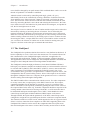


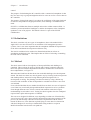
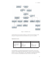

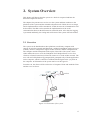
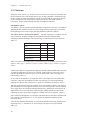
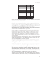
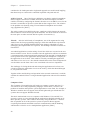

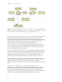

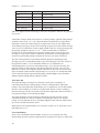
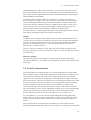
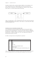

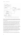
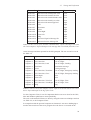


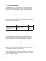
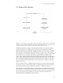
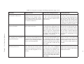

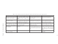


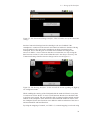
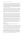
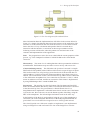
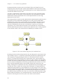
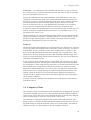
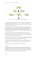

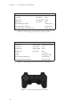
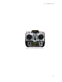
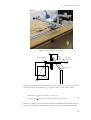

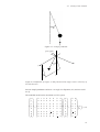

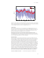

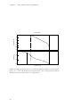
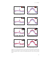
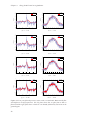

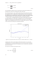
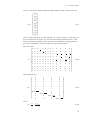


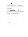
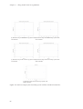

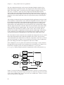


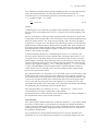
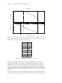

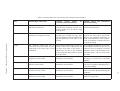
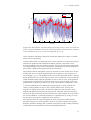

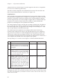


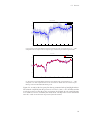


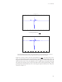
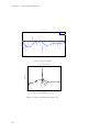


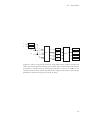

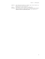
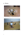

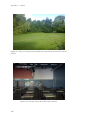
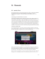
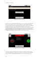


![PDF [1] - Dep SAE Soudage, Automatismes et Electronique location](http://vs1.manualzilla.com/store/data/005888267_1-8c649f384f0a877ffbc023ff9f75566c-150x150.png)