1
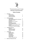
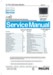
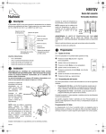
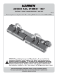
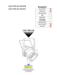
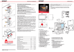
TerrAdaptor™
TerrAdaptor
Winch Brackets
The TerrAdaptor Standard and Capstan Winch Brackets are lightweight and
compact brackets designed specifically for use with the TerrAdaptor tripod
system. There are three options to choose from: the Standard Winch Bracket,
Capstan Winch Bracket and the Capstan Winch Bracket Assembly (includes the
Harken 40.2 ST two speed winch).
Standard Winch Bracket (P/N 230550)
The Standard Winch Bracket is designed primarily for mounting crank operated winches used in the
work and rescue markets. The standard winch bracket was designed specifically with the bolt pattern
predrilled and ready to assemble the DBI/SALA9000004 mounting bracket and the Tractel Winch
T2S5OG directly onto the bracket. Follow the winch manufacturer recommendations for proper
mounting of the winch to the bracket using the supplied hex bolts and lockwashers (4 each are
supplied). The bolts should be torque to 20 lb/ft (DO NOT OVER TIGHTEN).
Other winch models can be mounted to the standard bracket. The dimensions of the bracket are 3½”
x 9” x ½” thick and is made from aluminum plate. The top plate will need to be drilled and tapped with
additional holes to meet the specific bolt pattern of your winch. See the winch manufacturer
recommendations for proper mounting and do not exceed manufacturers rating.
The bracket is designed to be used with winches utilizing rope, wire rope or cable. If wire rope or
cable is selected, be sure to use the TerrAdaptor Steel Sheave Assembly (P/N 230360) rather than
the Standard TerrAdaptor Sheave Assembly (P/N 230350) as your re-direct accessory.
Capstan Winch Bracket (P/N 230551)
The Capstan Winch Bracket is designed specifically for mounting a Harken 40 ST or 40.2 ST capstan
winch. The top plate is predrilled and ready for assembly. Follow the Harken recommendations for
proper mounting of the winch to the bracket using the supplied stainless cap screws, washers and
hex nuts (5 each). The screws should be torque to 6 or 7 lb/ft (DO NOT OVER TIGHTEN).
The TerrAdaptor Capstan Winch Bracket employs a lightweight stainless loop that guides the rope
into the capstan at the correct angle for maximum grip of the
rope. The guide loop can also mind prussics which can
simplify progress capture rigging.
TerrAdaptor Users Manual Supplement – Winch Brackets
Attaching The Winch Bracket to the TerrAdaptor System
The bracket is normally located on the rear leg of a tripod, but it can be located on any leg provided
the rope or cable is safely routed. It can be attached anywhere along the smaller diameter Perf Tube.
It can also be attached at the junction between the Perf Tube and larger Mid Tube by lining up the
relief in the sideplates of the bracket at the junction of the two tubes as shown in the picture below.
Once positioned, insert the three long quick release pins (with rings) so that the ball detent is fully
exposed on the opposite side as shown in the picture below.
Attached at Junction
Ball should be visible
The bracket also has high strength auxiliary attach points (see Table 2-1) at each end for rigging
belays, progress capture, tie down, and other rigging needs.
Capstan Winch Bracket Assembly
The Capstan Winch Bracket Assembly comes fully assembled with the Harken 40.2 ST two speed
winch, including the Harken 10 inch lock-in aluminum speed grip handle. Simply attach the
assembly to the TerrAdaptor leg with the long quick release pins as described above. For more
information on the Harken winch go to www.harken.com.
Rigging the Capstan Winch
The rope is routed from the load, through the redirect accessory (pulley, sheave assembly or other
gear) located at the tripod head, through the guide loop on the winch bracket and then onto the
winch. Specifically, begin at the bottom of the capstan, wrap the rope clockwise around the capstan
several times (number of wraps varies with rope diameter) without overlapping until the rope has
reached the top of the drum. Finish by putting the tail of the rope over the chrome stripper arm and
then between the upper and lower spring loaded jaws of the self tailing mechanism. Install handle.
(Please see the Harken User Manual for further information on proper use of the winch).
Raise loads by turning the handle in the direction that provides the best
mechanical advantage for your situation. Depending on the weight of the
load and the speed needed to raise the load, it may be more efficient to
place one foot near the base of the tripod leg or lash the leg to the surface
for greater stability. Note that the winch can be rigged for progress capture
by attaching prussic or other progress capture devices to the rigging points
on the winch bracket.
TerrAdaptor Users Manual Supplement – Winch Brackets
Lower loads by using the capstan as a belay drum to provide friction. While retaining a firm grasp on
the rope tail and supplying tension on the capstan, unwind the rope from between the upper and
lower spring loaded jaws and then from the stripper arm. While remaining in control of the rope tail,
slowly decrease tension and allow the rope to slip on the capstan to lower the load at the desired
speed. Capstan winches must be tailed either manually or by means of the self tailing mechanism.
To return to a raise, again wrap the tail of rope over chrome stripper arm and then between the upper
and lower spring loaded jaws and turn with the handle.
The TerrAdaptor system employing a capstan style winch is used for raising and lowering typical
rescue loads of 300 to 600 pounds using ropes common to rope rescue. Capstan winches are not
designed to catch a falling load nor does it employ any type of braking mechanism. If fall protection
or a belay line is required then it should be rigged independently.
Also see www.harken.com for more information and recommendations for proper winch mounting and
use. Do not exceed winch manufacturers rating.
Best Practice:
Cable winches should be mounted on the inside of the tripod so the cable does not drag on the leg
tubes. Capstan winches are easier to operate when they are mounted on the outside of the leg.
When possible, secure feet directly to anchors to create a more rigid setup.
Care & Maintenance:
Check all components for bending and warping which could indicate overloading.
Auxiliary attach points can be both tied into and clipped into. As a result, pay careful attention to
sharp edges or burrs that may have developed. Lightly file or sand off burrs before use.
Warnings:
•
•
•
•
Carabiners clipped into auxiliary attach points should be positioned to avoid cross or side loading
Do not use the normal leg coupling pins to attach the winch bracket as they are too short and
could result in the winch bracket detaching from the leg and resulting in injury or death
See winch manufacturers recommendations for proper winch mounting and do not exceed
manufacturers rating when operating winches
Failure to maintain control of the rope tail on Capstan winches could result in injury or death due
to falls
TerrAdaptor Users Manual Supplement – Winch Brackets
Table 2-1 - Strengths of auxiliary attachment points
Auxiliary Attach Point
Lash Ring – Single Hole
Lash Ring – Opposing Holes
Talon Foot
Rocker Foot
Articulating Foot Adaptor
Quick Lash – Straight Pull
Quick Lash – Pulled to Side
Winch Brackets
Head Auxiliary Attachment Points
Breaking Strength
4,500 lbf. (20kN)
5,600 lbf. (25kN)
6,744 lbf. (30kN)
6,744 lbf. (30kN)
6,744 lbf. (30kN)
6,744 lbf. (30kN)
3,372 lbf. (15kN)
6,744 lbf. (30kN))
8,000 lbf. (36kN)
Manufactured By:
SMC – Seattle Manufacturing Corporation
6930 Salashan Parkway
Ferndale, WA 98248
USA
Phone: 360.366.5534
Fax: 360.366.5723
www.smcgear.net
www.TerrAdaptor.com
Distributed By:
Skedco, Inc
10505 SW Manhasset Drive
Tualatin, OR 97062
USA
Phone: 503.691.7909
Fax: 503.691.7973
www.Skedco.com
TerrAdaptor Users Manual Supplement – Winch Brackets
Pigeon Mountain Industries
4466 N US Hwy 27
LaFayette, GA 30728
USA
Phone: 706.764.1437
Fax: 706.764.1531
www.PMIRope.com
Installation and Maintenance Manual
MRW-01
Radial Winch 40.2 ST
Index
Introduction
3
Technical characteristics
Weight
Maximum working load
3
3
3
Outline
3
Installation
Procedure 1
Procedure 2
Installation procedure
Positioning the self-tailing arm
4
5
6
8
9
Maintenance
Washing
Maintenance table
Disassembly procedure
Exploded view with maintenance products
Assembly
9
9
9
9
13
14
®
Harken limited worldwide warranty
15
Ordering spare parts
15
Exploded view
16
Parts list
Radial Winch 40.2 STA
Radial Winch 40.2 STC
18
18
19
Radial Winch 40.2 ST
2
Installation and Maintenance Manual
Introduction - Technical characteristics - Outline
Introduction
This manual gives technical information on winch installation and maintenance, including
disassembling and reassembling.
This information is DESTINED EXCLUSIVELY for specialised personnel or expert users.
Installation, disassembling and reassembling of the winch by personnel who are not experts may
cause serious
damage to users and those in the vicinity of the winch.
®
for defective installation or reassembly of its winches.
Harken accepts no responsibility
®
In case of doubt the Harken Tech Service is at your disposal at [email protected]
This Manual is available only in English. If you do not fully understand the English language, do
not carry out the operations described in this Manual.
Technical characteristics
Power ratio
Gear ratio
1st speed
13,50 : 1
2,13 : 1
2nd speed
39,90 : 1
6,28 : 1
The theoretical power ratio does not take friction into account.
Weights
Weight (Kg)
ST A version
ST C version
3,8
5,4
Versions:
A = drum in anodised aluminium
C = drum in chromed bronze
Maximum working load
WARNING!
The maximum working load (MWL) for the 40.2 ST Radial Winch is 850Kg (1874 lb)
Subjecting the winch to loads above the maximum working load can cause the winch to fail or
pull off the deck suddenly and unexpectedly during high loads causing severe injury or death.
81 mm
Line entry height
Ø 80 mm
175 mm
Outline
Ø157 mm
Radial Winch 40.2 ST
3
Installation and Maintenance Manual
Installation
Installation
The winch must be installed on a flat area of the deck, reinforced if necessary to bear a load equal
to at least twice the maximum working load of the winch.
It is the installer's responsibility to carry out all structural tests needed to ensure that the deck can
bear the load.
®
Harken does not supply the screws needed to install the winch since these may vary depending
on the deck on which it is to be installed.
It is the installer's responsibility to choose the correct screws taking account of the loads they will
have to bear.
®
Harken assumes no responsibility for incorrect installation of its winches or for an incorrect choice
of mounting screws.
DANGER!
Incorrect installation of the winch may cause severe injury or
death. Consult the yard that built the boat in the case of doubt
over the correct positioning of the winch.
WARNING!
Failure to use the correct number and type of mounting fasteners
or failure to ensure the correct deck strength can result in the
winch pulling off the deck suddenly and unexpectedly during
high loads causing severe injury or death.
WARNING!
Verify the entry angle of the sheet. This must be 8° with tolerance
of ±2°, to avoid sheet overrides and damaging the winch or
making the winch inoperable leading to loss of control of the
boat which can lead to severe injury or death.
8°
drive gear
WARNING!
Mount the winch on the deck so that the drive gear is positioned
where the sheet enters the winch drum.
Incorrect position of drive gear can weaken winch leading to failure
which can cause an accident leading to severe injury or death.
NOTICE
You can find the icon
position.
SHEET
on the skirt to identify the drive gear
Once you have chosen the correct mounting position for the winch on the deck proceed with
installation.
Radial Winch 40.2 ST
4
Installation and Maintenance Manual
The winch can be installed following one of the two procedures below (Procedure1 or Procedure 2):
Procedure 1
To install the winch you must remove the drum and use Socket Head (SH) bolts.
Tools needed
One medium flat-bladed screwdriver
To identify the various parts, refer to the exploded view at the end of this Manual.
Torque to apply when assembling
1. Unscrew the central screw ( 2Nm/18 in-lb)
2. Slide off the hub n°28 and the cover n°29
3. Unscrew the three screws n°27
( 4Nm/35 in-lb)
4. Remove the self-tailing arm n°26 by
rotating and lifting it.
Radial Winch 40.2 ST
5
Installation and Maintenance Manual
5. Lift off the drum n°22
Install the winch on the deck in the position you have chosen, keeping in mind the limits described
on page 4 and using socket head (SH) bolts.
(See paragraph on installation)
Procedure 2
To install, you must remove the winch skirt and use hexagonal headed bolts.
Tools needed
One medium flat-bladed screwdriver
To identify the various parts, refer to the exploded view at the end of this Manual.
1. Remove the skirt n°2 with the help of
the screwdriver placed as shown by
the symbol
Radial Winch 40.2 ST
2. Take off the base n°2
6
Installation and Maintenance Manual
3. Position the 5 M6 hexagonal headed
bolts in their holes
a
a
4. Reposition the skirt n°2 in its housing
5. Press down the skirt to position it correctly
NOTICE
Make sure the skirt is correctly clipped on to the base of the winch.
Install the winch on the deck in the position you have chosen, keeping in mind the limits described
on page 4 and using hexagonal headed bolts.
(See paragraph on installation)
Radial Winch 40.2 ST
7
Installation and Maintenance Manual
Installation procedure
Carry out Procedure 1 or Procedure 2, then install the winch on the deck in the chosen position.
A. Position the base of the winch on the deck and mark the position of the holes or use the drilling
cut-out template at the point where you have decided to place the winch.
Below is a reduced scale diagram.
®
The drilling cut out template is available on the Harken website, www.harken.com
B. Remove the winch and drill the five 6.2 mm diameter holes.
C. Bolt the base of the winch to the deck using five M6 Socket Head (SH) bolts for Procedure 1 or five
®
hexagonal headed M6 bolts for Procedure 2 (neither is supplied by Harken ), correctly chosen for
the thickness and type of the boat deck. Consult the yard that built the boat in case of doubt.
WARNING!
To install the winch on the deck, use only bolts in A4 stainless steel (DIN 267 part11).
Bolts made of other materials may not have sufficient strength or may corrode which can
result in winch pulling off deck suddenly and unexpectedly during high loads causing
severe injury or death.
NOTICE
To mount winches on the deck, do not use countersunk bolts.
D. Fill the mounting holes with a suitable marine sealant.
E. Remove the excess adhesive/sealant from the holes and base drainage channels
Radial Winch 40.2 ST
8
Installation and Maintenance Manual
Maintenance
F. Reassemble the winch following the steps in Procedure 1 or Procedure 2 in the reverse
order, and apply the products indicated in the section on maintenance.
NOTICE
Before closing the winch, make sure the holes and drainage channels in the base of the winch
are not obstructed.
Positioning the self-tailing arm
Position the self-tailing arm so that the line leaving the winch is led into the cockpit.
Maintenance
Washing
Winches must be washed frequently with fresh water, and in any case after each use.
Do not allow teak cleaning products or other cleaners containing caustic solutions to come into
contact with winches and especially anodised, chrome plated or plastic parts.
Do not use solvents, polishes or abrasive pastes on the logos or stickers on the winches.
Make sure that the holes and drainage channels in the base of the winch are not obstructed so that
water does not collect.
Maintenance table
Winches must be visually inspected at the beginning and end of every season of sailing or racing.
In addition they must be completely overhauled, cleaned and lubricated at least every 12 months.
After an inspection, replace worn or damaged components. Do not replace or modify any part of the
winch with a part that is not original.
WARNING!
Periodic maintenance must be carried out regularly. Lack of adequate maintenance
shortens the life of the winch, can cause serious injury and also invalidate the winch
warranty. Installation and maintenance of winches must be carried out exclusively by
specialized personnel.
®
In the case of doubt contact Harken Tech Service at [email protected]
Disassembly procedure
Tools needed
One medium flat-bladed screwdriver
A number five hex key
Rags
To identify the various parts refer to the exploded view at the end of this Manual.
Radial Winch 40.2 ST
9
Installation and Maintenance Manual
Torque to be applied in assembly phase
Carry out Procedure 1 as shown in the paragraph on winch installation and then do the following:
6. Completely unscrew the three screws n° 27
7. Remove the self-tailing arm support n°21
8. Slide out the central shaft n°19
9. Unscrew the 6 hex screws n°16
( 8Nm/71 in-lb)
10. Remove the drum support n°15
Important: washer n°12 may remain
inside the drum support!
11. Remove the washer n°12
Radial Winch 40.2 ST
10
Installation and Maintenance Manual
12. Remove the gear n°7 and remove the
pawls n°5. To facilitate the operation press
the spring against the pawl with a blade.
13. Slide off gear n°3
14. Slide off gear n°14
15. Slide off gear n°10
16. Remove the pawls n°5. To facilitate the
operation press the spring against the
pawl with a blade.
17. Remove washer n°9
Radial Winch 40.2 ST
11
Installation and Maintenance Manual
If it is necessary to replace any jaws of the winch, proceed as follows:
II. Remove the jaws n°24
I. Unscrew the 4 screws n°25
( 4Nm/35 in-lb)
Once the winch is completely disassembled, clean the parts: use a basin of diesel oil to soak
metal components and rinse plastic parts in fresh water. Once you have done this, dry the parts
with cloths that do not leave residue.
Inspect gears, bearings, pins and pawls for any signs of wear or corrosion.
Carefully check the teeth of gears and ring gears to make sure there are no traces of wear.
Check the roller bearings and check there are no breaks in the bearing cages.
Replace worn or damaged components.
Carry out maintenance on components using the products listed below.
For more information on which products to use where, refer to the exploded diagram below.
Use a brush to lightly lubricate all gears, gear pins, teeth and all moving parts with grease.
Lightly lubricate the pawls and springs with oil. Do not use grease on the pawls!
Radial Winch 40.2 ST
12
Installation and Maintenance Manual
Exploded view with maintenance products
G
1
G
A Anti-seize
G Harken® Grease
O Harken® Pawl Oil
A
A
A
G
G
G
G
2
G
O
O
G
G
G
G
A
1Apply
2Apply
Radial Winch 40.2 ST
13
Harken grease on assy socket screw
Harken grease on drum gear
®
®
Installation and Maintenance Manual
Assembly
Make sure that the holes and drainage channels in the base of the winch are not obstructed
Assemble the winch in the reverse order of the sequence in the section on disassembly.
To tighten bolts, use the torque indicated in the disassembly procedure.
When positioning the stripper arm,
align the peeler with it.
OIL
If the jaws have been disassembled,
insert peeler between the two jaws,
taking care that the letters TOP on the
peeler are facing upwards.
To assemble the pawls:
correctly position the spring in its housing as
shown at left. Hold the spring closed and slide
the pawl into its housing. Once in position,
check that the pawls can be easily opened and
closed with a finger.
®
In case of doubt concerning the assembly procedure contact Harken Tech Service: [email protected]
Radial Winch 40.2 ST
14
Installation and Maintenance Manual
Harken® limited worldwide warranty - Ordering spare parts
Harken® limited worldwide warranty
®
®
Refer to the Harken Limited Worldwide Warranty in the Harken Catalogue and on the website
www.harken.com
Ordering spare parts
®
Spare parts can be requested from Harken as
®
described in the Harken Limited Worldwide
Warranty, indicating the part number in the
Parts List and including the serial number of
the winch for which the parts are required.
W XXXXX
XXXXXXXXX
The serial number of the winch is printed on
a plate on the drum support of the winch.
Manufacturer
Harken® Italy S.p.A.
Tech Service
Email: [email protected]
Via Marco Biagi, 14
22070 Limido Comasco (CO) Italy
Tel: (+39) 031.3523511
Fax: (+39) 031.3520031
Email: [email protected]
Web: www.harken.com
Customer Service
Tel: (+39) 031.3523511
Email: [email protected]
Headquarters
Harken®, Inc.
Tech Service
Email: [email protected]
1251 East Wisconsin Avenue
Pewaukee, Wisconsin 53072-3755 USA
Tel: (262) 691.3320
Fax: (262) 691.3008
Email: [email protected]
Web: www.harken.com
Radial Winch 40.2 ST
Customer Service
Tel: (262) 691-3320
Email: [email protected]
15
Installation and Maintenance Manual
Exploded view 1/2
28
29
27
26
22
21
23
25
18
24
17
15
20
16
Radial Winch 40.2 ST
16
Installation and Maintenance Manual
Exploded view 2/2
19
8
12
11
6
7
5
13
5
10
6
14
9
4
3
1
2
Radial Winch 40.2 ST
17
Installation and Maintenance Manual
Parts list
Radial Winch 40.2 STA
A= drum in anodised aluminium
Pos.
1
Q.ty
1
2
3
4
5
6
7
8
9
10
11
12
13
14
15
16
17
18
19
20
21
22
23
24
1
1
1
4
4
1
1
1
1
1
1
1
1
1
6
1
2
1
1
1
1
1
1
Code
A94141300
A94141400
S 41302 00 04
S 41303 00 04
S 00008 00 03
S 00038 00 01
S 41283 00 41
S 41300 00 04
S279090002
S 41297 00 04
S 41285 00 41
S 41312 00 02
S 41307 00 04
A94130500
A94141500
M0635103
S 41315 00 82
A74136000
A94139000
S418760063
S4129400A0
S 41417 00 53
S281680097
A94131800
Description
Winch 40 Base Assy
Winch Serial Number Sticker
Assembly - Skirt Winch 40**
Gear Z12
Pawls Carrier Ø8xN2*
Pawl Ø8*
Pawl Spring dia 8*
Gear Z23
Pin
Washer 36x9,5x1*
Gear Z20
Pinion Z13
Washer Ø22.5xØ45x1*
Pin
Assy - Gear Z20
Assy - Housing Winch 40
Socket head screw M6x16 UNI 5931*
Washer Ø62xØ80x1.5*
Bearing Ø56xØ68x24*
Assy - Central Shaft W36/40
Winch Serial Number Sticker
Stripper arm support
Drum A W40
Red line
Assy - Winch 40 Jaws
Lower Jaw W35/40
Upper Jaw w35/40
Peeler W20-40
Spring
25
26
27
28
4
1
3
1
M0601803
S 41420 00 19
M6007103
A94136400
Screw UNI EN ISO 1207:1996 - M6x35 - A4*
Stripper Arm W35/40
Screw M6x50 UNI6107*
Assy - Socket W20-80
Screw M8x20 UNI 6109*
Washer Ø7.7xØ25x5.8*
Socket Handle W20/80
29
1
S 41419 00 A5
Cover 2 speed W40
*Service kit available; see winch kit section on the website www.harken.com
**Winch product sticker
Radial Winch 40.2 ST
18
Installation and Maintenance Manual
Parts list
Radial Winch 40.2 STC
C=drum in chromed bronze
Pos.
1
Q.ty
1
2
3
4
5
6
7
8
9
10
11
12
13
14
15
16
17
18
19
20
21
22
23
24
1
1
1
4
4
1
1
1
1
1
1
1
1
1
6
1
2
1
1
1
1
1
1
Code
A94141300
Description
Winch 40 Base Assy
A94141400
S 41302 00 04
S 41303 00 04
S 00008 00 03
S 00038 00 01
S 41283 00 41
S 41300 00 04
S279090002
S 41297 00 04
S 41285 00 41
S 41312 00 02
S 41307 00 04
A94130500
A94141500
M0635103
S 41315 00 82
A74136000
A94139000
S418760063
S4129400A0
S 414180043
S281680097
A94131800
Assembly - Skirt Winch 40**
Gear Z12
Pawls Carrier Ø8xN2
Pawl Ø8*
Pawl Spring dia 8*
Gear Z23
Pin
Washer 36x9,5x1*
Gear Z20
Pinion Z13
Washer Ø22.5xØ45x1*
Pin
Assy - Gear Z20
Assy - Housing Winch 40
Socket head screw M6x16 UNI 5931*
Washer Ø62xØ80x1.5*
Bearing Ø56xØ68x24*
Assy - Central Shaft W36/40
Winch Serial Number Sticker
Stripper arm support
Drum C W40
Red line
Assy - Winch 40 Jaws
Winch Serial Number Sticker
Lower Jaw W35/40
Upper Jaw w35/40
Peeler W20-40
Spring
25
26
27
28
4
1
3
1
M0601803
S 41420 00 19
M6007103
A94136400
Screw UNI EN ISO 1207:1996 - M6x35 - A4*
Stripper Arm W35/40
Screw M6x50 UNI6107*
Assy - Socket W20-80
Screw M8x20 UNI 6109*
Washer Ø7.7xØ25x5.8*
Socket Handle W20/80
29
1
S 41419 00 A5
Cover 2 speed W40
*Service kit available; see winch kit section on the website www.harken.com
**Winch product sticker
Radial Winch 40.2 ST
19
Installation and Maintenance Manual