1
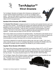
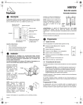
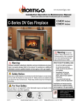
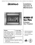
ECONO-PLUS 36DV-TV
INSTALLING AND OPERATING
YOUR ECONO-PLUS 36DV
GAS-BURNING FIREPLACE
Please leave this manual with the owner
CHECK LOCAL CODES PRIOR TO INSTALLATION
FOR YOUR SAFETY
IF YOU SMELL GAS:
FOR YOUR SAFETY:
1. OPEN WINDOWS.
2. DON'T TOUCH ELECTRICAL SWITCHES
3. EXTINGUISH ANY OPEN FLAME.
4. IMMEDIATELY CALL YOUR GAS SUPPLIER.
DO NOT STORE OR USE ANY FLAMMABLE
VAPOURS OR LIQUIDS NEAR THIS OR ANY
OTHER GAS-BURNING APPLIANCE.
READ INSTRUCTIONS CAREFULLY BEFORE INSTALLING
MODEL
ECONO-PLUS 36DV-TV
CANADIAN HEATING PRODUCTS INC.
13120 - 76th Avenue, Surrey, B.C. Canada; Phone: (604) 597-3115 Fax: (604) 597-3096
09/96
Page 1 of 14
E36DV-TV
INTRODUCTION
INSTALLING THE FIREPLACE
The Econo Plus 36DV-TV is rated at 16,000 BTUs. (4.16 Kilowatts)
for Natural & Propane gas.
The Econo Plus warranty will be voided by, and Econo Plus
disclaims any responsibility for, the following actions:
- Modification of the fireplace and/or components including
Direct-Vent assembly or glass doors.
- Use of any component part not manufactured or approved by
Econo Plus in combination with a Econo Plus fireplace system.
- Installation other than as instructed in this manual.
Consult your local Gas Inspection Branch about the particular
requirements concerning installation of factory-built gas fireplaces.
Installation & repairs should be done by a qualified contractor,
and installation must conform with the current CAN/CGA
B-149.1 and .2 Gas Installation Code and local
regulations.
The Econo Plus 36DV-TV clearances to combustible materials are
0" back, 1" sides, 0" floor and 4" top. The Econo Plus 36DV-TV
must not be installed any closer than 8 inches to any unprotected
combustible wall perpendicular to the fireplace opening.
For protection against freezing temperatures, it is recommended
that outer walls of the chase be insulated with a vapour barrier. This
will reduce the possibility of a cold-air convection current on the
fireplace.
The framing dimensions are shown below:
12
39
19
CAUTIONS
16 1/4
10 1/4
* Due to its high operating temperatures, the appliance should be
located out of traffic & away from furniture and draperies.
37 1/2
* Children and adults should be alerted to the hazards of the high
surface temperature, which could cause burns or clothing ignition.
55
12
* Young children should be carefully supervised when they are in
the same room as the appliance.
Opening for termination.
42" min. from floor to
center of the opening.
12
* Clothing or other flammable materials should not be placed on
or near the appliance.
SELECTING YOUR FIREPLACE LOCATION
The fireplace may be installed in any location that is free of air
condition ducts, electrical wiring and plumbing. Safety, as well as
efficiency of operation, must be considered when selecting the
fireplace location. Try to select a location that does not interfere
with room traffic, has adequate ventilation, and offers an accessible
pathway for Direct Vent & Combustion Air Kit installation.
The fireplace dimensions are shown below:
NOTE: SEE FIGURE 2 FOR FRAMING DIMENSIONS
37 1/2
FIGURE 2. FRAMING DIMENSIONS
INSTALLING THE GAS LINE
19
16 1/4
10 1/4
37 1/2
33
39 1/2
FIGURE 1. FIREPLACE DIMENSIONS
09/96
36
17
The gas line must be installed before finishing the Econo Plus
36DV-TV Fireplace. Natural Gas requires an inlet pressure of
7" W.C. & a manifold pressure of 3.5" W.C. Propane Gas
requires an inlet pressure of 11" W.C. & a manifold pressure of
10.5" W.C. It is also required that provisions be made for a
1/8" N.P.T. plugged tapping and be accessable for test gauge
connection immediately upstream of the gas supply controls to
the appliance. The fireplace gas connection and the main
operating gas valve is located behind the removable brass trim
at the bottom of the unit and need only be attached to the gas
line with an approved fitting, as required by the CAN/CGA
B-149.1 and .2 Gas Installation Code.
CAUTION
*After gas line is connected, it is a Can/CGA B149.1 & .2 code requirement
(Section 8.25.3 (e)) that "each appliance connection, valve, valve train, shall
be checked while under normal operating pressure with either a liquid solution,
or leak detection device, to locate any source of leak." Tighten any areas where
bubbling appears or leak is detected until bubbling stops completely or leak
is no longer detected. Do NOT use a flame of any kind to test for leaks.
Page 2 of 14
E36DV-TV
DIRECT VENT TERMINATION LOCATION
This section is used to determine where your direct
vent termination will be located.
VENT TERMINATIONS SHALL NOT BE RECESSED IN
WALLS OR SIDING.
INSTALLATION OF DIRECT VENT
A complete Econo Plus 36DV-TV vent system may comprise of
six individual components: (see figure 5. page 4)
A - Termination
B - Stucco Kits
CAUTION
C - Solid section & elbow
1). Extremely important: In heavy snow areas take extra
care to prevent against blocking vent termination with
snow removal equipment.
2). Flue gases exiting vent terminals are very hot and must
not be restricted to assure fireplace combustion is not
affected.
3). Do not place, build any obstruction, plant any bushes
or for any reason attempt to conceal the vent
termination. To do so will affect the operation of
the fireplace and may be hazardous.
4). National Standards require that vent terminations be
protected with an additional screen on patio's, decks and
any areas accessible to public. For maximum safety we
recommend all terminals below 7' from grade level be
installed with a certified Econo Plus protective screen. (MTKG)
FOR DETAILED SKETCH OF ALLOWED
TERMINATION LOCATIONS SEE APPENDIX A
FOR VINYL SIDING APPLICATIONS ALL MTK
TERMINATIONS MUST BE INSTALLED WITH A
HEAT SHIELD (MTKG) TO PROTECT THE SIDING
FROM ANY HEAT DAMAGE. MTKO TERMINATIONS
DO NOT REQUIRE A HEAT SHIELD.
D - Flex sections
E - Solid sections
F - 90 degree elbow
MTK-5 (5" length)
MTK-9 (9" length)
MSR (stucco frame)
MOSR (stucco can)
MIHR-6 (6 ft. length)
MIHR-10 (10 ft. length)
MFL-1 (1' 6" section)
MFL-2 (2' 6" section)
MFL-3 (3' 6" section)
MFL-4 (4' 6" section)
MEXT-1 (1' 6" section)
MEXT-2 (2' 6" section)
MEXT-3 (3' 6" section)
MEXT-4 (4' 6" section)
MEL90 (90 deg. elbow)
Example: For our shortest venting configuration use components A, B, and F. (see Figure 5).
Example: A 10' section and elbow (MIHR-10) used in
conjunction with 3 ft. flex section (MFL-3) will, when extended
in a five foot chase, allow for a maximum horizontal run of
twelve and one-half feet from the centre of the fireplace to
outside wall and a minimum of 7'6" when retracted in opposite
direction (see Figure 6 and 7).
"D" flex sections and "E" solid sections may be used in
conjunction with one another to obtain different possible
horizontal length installations. NOTE: Flex section must not
exceed maximum horizontal length of 3 feet. (see Figure 7.1)
CAUTIONS AND REQUIREMENTS
IMPORTANT:
When using MTK or MTKO with
MOSR: Framed opening must be 12"
X 12"
using MTK or MTKO:
* When
Framed opening must be 11" X 11"
FIGURE 4.
*12
*12
VENT TERMINATION FRAMING.
Note: DO NOT STRETCH flexible connector to gain
extra length. These connectors are Flexible only to
allow for directional changes, which must not exceed 90
degrees.
A minimum height of 43" to centre of horizontal flue is
required.
All vent pipes must maintain a minimum of 1"
clearance to combustible materials.
Note: It is imperative for satisfactory operation of the
Econo Plus 36DV-TV fireplace that no venting component be modified in any way. All components have been
manufactured to eliminate the need for modification
when properly selected and installed.
MTK-5 or MTK-9
09/96
MTKO-5 or MTKO-9
Page 3 of 14
E36DV-TV
C
A
A
7 1/2 ft. from
center of fireplace
10 ft. from center of elbow
Solid section includes
90 degree elbow
D
Stucco Can
Vent Termination
B
E
3 ft. flex
section
4"
B
F
10"
43"
Hearth
FIGURE 7. RETRACTED 10' SECTION
FIGURE 5.
TYPICAL INSTALLATIONS.
3, or 4 ft. flex section
turned 90 degrees.
Stucco Can
Vent Termination
3 ft. Max
HORIZONTAL VENTING
All vent pipes must maintain a minimum of 1" clearance to
combustible materials.
**NOTE:
All dimension lengths for vertical or horizontal
runs are measured from center of the 7" elbow.
A Horizontal length (see venting graph)
B Vertical length (see venting graph)
10 Ft Section
MIHR-10
Center of 7" elbow
to outside wall
6 Ft Section
MIHR-6
12 1/2 Ft.
07 1/2 Ft.
Maximum extended length
Maximum retracted length
8 1/2 Ft.
3 1/2 Ft.
FIGURE 7.1 HORIZONTAL FLEX
INSTALLATION
12 1/2 ft. from center of fireplace
A
10 ft. from center of elbow
Solid section includes
90 degree elbow
Stucco Can
Vent Termination
10' Max
3 ft. flex section
B
Header
Wall Thickness
(4" - 12")
Hearth
FIGURE 6. EXTENDED 10' SECTION
09/96
FIGURE 8.TYPICAL VENT TERMINATIONS
AND FIREPLACE LOCATIONS
Page 4 of 14
E36DV-TV
INSTALLATION OF VERTICAL DIRECT VENT
A complete Econo Plus 36DV-TV vertical vent installation may
comprise of the following components:
A - Termination
B - Flex sections
C - Solid sections
D - Support Ring & Plate
E - 7" Firestop
F - Roof Flashing
Storm collar
Roof flashing
2 Feet
MVTK-1
MFL-1 (1' 6" section)
MFL-2 (2' 6" section)
MFL-3 (3' 6" section)
MFL-4 (4' 6" section)
MEXT-1 (1' section)
MEXT-2 (2' section)
MEXT-3 (3' section)
MEXT-4 (4' section)
MEXT-6 (6' Section)
MSPXT-7 (7" Support
Plate & Ring)
FS-7 (7" Firestop)
MRF-16 (1/12 to 6/12 pitch)
MRF-12 (6/12 to 12/12 pitch)
VERTICAL DIRECT VENT TERMINALS
Support ring
Support plate
Firestop
Minimum 1"
clearance to all
combustibles
materials
FIGURE 9A.
Shall not be installed;
- Less than two feet above the highest point where vent
passes through the roof.
2 Feet
- Less than six feet from a mechanical air inlet.
- Less than three feet from a parapet wall.
Support straps
Support ring
Offsets;
- A maximum of two offsets with 90 degree bends may
be made and shall not exceed total length of 25% of
the vertical vent height, when measured center to
center of piping.
EXAMPLE:
(see figure 2)
Typical vent installaion
20' vertical vent
2 - 2' offsets required
25% of 20' = 4' max. offset allowed
this venting system complies to
instruction requirements.
- Maximum vent height is 28 feet above fireplace.
20 Feet
Firestop
Minimum 1"
clearance to all
combustibles
materials
Support ring
Support plate
Firestop
2'
- Minimum clearances 1" from vent to all combustible
materials must be maintained.
FIGURE 9B.
09/96
Page 5 of 14
E36DV-TV
VENTING GRAPH
Venting graph is used for top vent direct vent model only.
How to use the venting graph:
1 Determine the height for the centre of the 7" vent
elbow and mark a horizontal line until it intersects
with the slanted graph line.
2. From the point of this intersection draw a vertical line
to the bottom line of the graph.
INSTALLING THE REMOTE SWITCH
The Econo Plus 36DV-TV is equipped with a remote-operated
valve, located behind the removable brass grille, to the right of the
gas control valve (refer to figure 14.) The valve is pre-wired and
completely self contained to generate its own power DO NOT
connect any external power to it. Note: The switch location must
not exceed 30' from fireplace.
3. Select the indicated dimension and position the
fireplace in accordance with the same.
Example A:
If the vertical dimension from the floor of the fireplace
is 42" the horizontal run to the wall flange of the vent
termination must not exceed 24".
Example B:
If the vertical dimension from the floor of the fireplace
is 60" the horizontal run to the wall flange of the vent
termination must not exceed 64".
Example C:
If the vertical dimension from the floor of the fireplace
is 72" the horizontal run to the wall flange of the vent
termination must not exceed 120". (Maximum
allowable horizontal length).
C
B
Vertical
A
Horizontal
VENTING GRAPH
GENERAL VENT/PIPE INFORMATION
1.) All joints must be secured with the minimum of two screws
per joint.
2.) Horizontal runs must be supported by a minimum of two
supports per horizontal run. A minimum of one screw on
each side of support is also required.
3.) Both ends of the vertical sections are slip sections and are
made to slide over fireplace outlets and horizontal section
inlets.
09/96
Page 6 of 14
E36DV-TV
FIREPLACE MANTEL AND FACING
Combustible mantels and mouldings may be safely
installed over the top and on the front of the fireplace
provided that they do not project beyond shaded area
shown in figure 10A. Side wall clearances are 0". Combustible surrounds may be installed with 0" clearance to
the side of the fireplace as shown in figure 10B.
FIREPLACE FACING
When selecting the finish material for your fireplace, it is
important to remember the following: BRASS TRIMS
MUST NOT BE OBSTRUCTED IN ANY WAY - to do
so restricts the air supply for the control compartments
and heat exchanger it also prevents access for servicing
controls.
The face of the fireplace may be painted to match the room
decor, provided you use a heat-resistant paint. Decorative
facing must not extend past the fireplace opening at all,
because it will interfere with the access to retainers for
removal of glass panel and combustion door.
MANTELS & SURROUNDS
NOTE: National Canadian Gas Association mantel test
requirements are for fire hazard prevention to combustible materials.
New technology, to meet consumer and government
demands for the wise use of energy, has prompted us to
manufacture many models of fireplaces which are hot,
fuel and energy efficient.
Please be aware; temperatures over the mantel will rise
above normal room temperature and walls above
fireplace may be hot to touch.
We recommend careful consideration be given to the
effects of elavated mantel temperatures which may be
in excess of product design, for example: candles,
plastic or pictures. This can cause melting, deformation,
discoloration or premature failure of T.V. and radio
components.
Painting: Special care is recommended by the Master
Painters and Decorators Association, when painting the
fireplace surrounds, to select and apply a quality Alkyd
sealer prior to the applying of latex paints. This is to
prevent leaching of water from evaporation and causing
a brownish staining effect to paint over coats.
FIGURE 10B. COMBUSTIBLE SURROUNDS
FIGURE 10A. COMBUSTIBLE MANTLES & FACINGS
09/96
Page 7 of 14
E36DV-TV
INSTALLING LOG SET
REMOVAL OF OUTER DOOR
Easily removed for cleaning and servicing. Although this pane is
made of a very tough tempered glass, always handle it carefully and
place in a safe location where it will not be broken or damaged.
To remove the outer glass panel lift upwards and outwards. This will
release the panel from the mounting pins. See Figure 11.
The EC-Plus 36DV-TV is supplied with four(4) very attractive
cultured oak logs. To install simply place log "A's" rectangular
shaped extension into the log mounting slot located on rear wall
of the burner assembly. Place log "B" onto front log slots.
Place log "C" and log "D" onto pins on the burner bar as shown
below.
D
C
A
B
Lift panel upwards
and outwards until
panel releases from
mounting pins.
FIGURE 11.
OUTER GLASS DOOR
Wire to
wall switch
REMOVAL OF INNER DOOR
To remove inner glass door, outer glass door must first be removed.
Next turn the safety door locks outwards as illustrated in Figure 12.
Note: When turning and unlocking the safety door locks a small
additional pressure is required to start the unlocking procedure.
This is because a latch pin of the safety door lock is seated into a latch
plate notch (see Figure 13). This ensures the safety door lock is in
its correct position, maintaining the door seal is under constant
spring pressure.
IMPORTANT: For your safety when replacing inner door to its original position always assure the
safety door latch pin is correctly positioned with the
notch in the latch plate. (see Figure 13).
Turn
Turn
Control Valve
LIGHTING PILOT AND MAIN BURNER
To light pilot it is necessary that you remove outer and inner glass
door (refer to sections on glass door removal). The gas control valve
is located behind the brass trim in the centre of the fireplace (see
Figure 14 below). Before lighting the pilot, make sure that the gas
line is connected and the gas shut-off valve is turned to the ON
position. To light the pilot we recommend the use of a long match
or removal of log“D”:
a) Partially depress and turn dial on gas control valve to “OFF”
position and wait 5 minutes.
b) Turn dial to pilot position, depress dial and light pilot burner,
hold for1 minute, then release. If pilot does not remain
ignited, repeat, allowing a longer time to elapse before
releasing dial.
c) Re-install inner and outer glass door.
NOTE: For your protection and safety, main gas burner can not
be activated until inner glass door has been re-installed to activate
a safety cut off switch.
d) To light the main burner, turn dial to “ON”, then turn on
remote switch.
e) Turn off flame with remote switch. For complete shut down,
slightly depress gas control valve dial and turn to “OFF”
position.
FIGURE 12.
INNER GLASS DOOR
Knotch
Door
FIGURE 13.
09/96
FOR ALTERNATE
GAS VALVE SEE
FIGURE 16 ON THE
NEXT PAGE.
SAFETY LOCK
FIGURE 14. ROBERT SHAW GAS CONTROL VALVE
Page 8 of 14
E36DV-TV
TROUBLESHOOTING
PILOT BURNER ADJUSTMENT
1. Remove Pilot Adjustment Cap. (see figure 14 or 16)
2. Adjust pilot screw to provide properly sized flame. See Figure
15 or for properly sized flame.
3. Replace pilot adjustment cap.
4. Leak test with a soap solution after installing or servicing with
main burner on. Coat pipe and tubing joints, gasket etc. with
soap solution. Bubbles indicate leaks. Tighten any areas where
the bubbles appear until the bubbling stops completely.
3/8 to 1/2 Inch
Power Generator
Pilot
Burner
The following is a troubleshooting chart of possible problems:
PROBLEM
CORRECTIVE ACTION
Noisy Pilot Flame
Remove pilot adjuster cap, located
next to gas shut off valve. Flame is
decreased by turning adjustment
screw clockwise.
Pilot won’t ignite
Disconnect remote wires and try to
light pilot. If pilot now works,
remote connections are faulty.
Check wiring diagram figure 14.
Main burner will
not light
1. Check wiring (see figure 14.)
2. Check wall switch for proper
connection.
3. Check door safety switch located
center of bottom door rail
4. Burner ignites, adjust activating
pin bottom center of inner glass door.
5. Burner does not ignite, check
electrical contacts of the door safety
switch.
FIGURE 15. PILOT BURNER ADJUSTMENT
MAINTENANCE
The appliance should be inspected before use and at least annually
by a professional service person. More frequent cleaning may be
required due to excessive lint from carpeting, bedding material,
etc. It is imperative that burner control compartments, burners and
circulating air passageways of the appliance be kept clean. For
your convenience a 1/8" pressure tap is supplied on the gas valve
for a test gauge connection. See Figure 14. For Natural gas the gas
line requires an inlet pressure of 7" W.C. and a manifold pressure
of 3.5" W.C. For Propane gas the gas line requires an inlet pressure
of 11" W.C. and a manifold pressure of 10.5" W.C. Always keep the
fireplace area clear and free of combustible materials, as well as
gasoline and other flammable vapours and liquids.
If your Econo Plus 36DV-TV still does not operate correctly,
consult your dealer or the manufacturer.
All service and repairs should be performed by a qualified
agency.
All spare parts, optional fans (see optional fan instruction guide),
and optional trim finishes are available from Canadian Heating
Products Inc. or your local dealer.
CLEANING
When fireplace is first activated some smoking and visible film on
the glass may occur, this is a normal condition of heat burning of
protective coatings on new metal.
- Products of combustion do deposit a visable film on the glass
which must be cleaned periodically. Film can easily be
removed by removing inner and outer doors, handling
carefully, and cleaning with normal liquid household products.
The Econo Plus 36DV-TV has a ten-year limited warranty
on the firebox, a five-year warranty on the main burner, pilot
burner, and cultured oak logs; and a one-year warranty on
the gas control valve and glass doors.
WARNING: Do not attempt to clean glass when hot.
Do not clean glass with abrasive materials as any glass
etching may cause premature glass failure.
- Silicone seals on inner door during initial firing will "off gas",
leaving a visual deposit of a white substance on combustion
chamber walls. This can easily be removed using normal
household products.
- Use a vacuum cleaner or whisk broom to keep the control
compartment, burner, and firebox free from dust and lint.
- Logs may be cleaned periodically with soap and water to
remove soot.
CAUTIONS
* Fireplace gas control must be in the “OFF” position and
pilot and main burners extinguished when cleaning
appliance with a vacuum.
* Doors and logs can get very hot, handle only when logs are
cool.
09/96
Pilot Adj. Cap
FIGURE 16. WHITE ROGERS GAS CONTROL VALVE
Page 9 of 14
E36DV-TV
ECONO-PLUS 36DV-TV
GAS FIREPLACE WARRANTY
THE WARRANTY
The Companies warrants the Montigo Gas Appliance to be free from defects in materials and workmanship at the time of manufacture. On the
Montigo, there is a ten-year warranty on the firebox and its components, a five-year warranty on the main burner, pilot burner and a oneyear
warranty on the gas control valve and glass doors.
REMEDY AND EXCLUSIONS
The coverage of this Warranty is limited to all components of the Gas Appliance manufactured by The Companies.
This Warranty only covers Montigo Gas Appliances installed in the United States or Canada.
If the components of the Gas Appliance covered by this Warranty are found to be defective within the time frame stated (see The Companies
right of
investigation outlined below). The Companies will, at its option, replace or repair defective components of the Gas Appliance
manufactured by The Companies at no charge, and will also pay for reasonable labour costs incurred in replacing or repairing components. If
repair or replacement is not
commercially practical, The Companies will, at its option, refund the purchase price of the Montigo Gas
Appliance.
This Warranty covers only parts and labour as provided above. In no case shall The Companies be responsible for materials, components,
or construction which are not manufactured or supplied by The Companies, or for the labour necessary to install, repair or remove such
materials,
components or construction. All replacement or repair components will be shipped F.O.B. the nearest The Companies
factory.
QUALIFICATIONS TO THE WARRANTY
The Gas Appliance Warranty outlined above is further subject to the following qualifications:
(1) The Gas Appliance must be installed in accordance with The Companies installation instructions and local building codes. The Warranty
on this Montigo Gas Appliance covers only the component parts manufactured by The Companies. The use of components manufactured by
others with this Montigo Gas Appliance could create serious safety hazards, may result in the denial of certification by recognized national
safety
agencies, and could be in violation of local building codes. This warranty does not cover any damages occurring from the use of
any components
not manufactured or supplied by The Companies
(2)The Montigo Gas Appliance must be subjected to normal use. The Gas Appliances are designed to burn gas only.
Burning conventional fireplace fuels such as wood, coal or any other solid fuel will cause damage to the Gas Appliance, will produce
excessive temperatures and will result in a fire hazard.
LIMITATIONS ON LIABILITY
It is expressly agreed and understood that The Companies sole obligation, and purchaser's exclusive remedy under this
Warranty, under any other warranty, expressed or implied, or in contract, tort or otherwise, shall be limited to replacement,
repair, or
refund, as specified above.
In no event shall The Companies be responsible for any incidental or consequential damages caused by defects in its prod ucts,
whether such
damage occurs or is discovered before or after replacement or repair, and whether or not such damage is
caused by The Companies negligence.
Some states do not allow the exclusion or limitation of incidental or consequential damages, so the above limitation or exclusion may not apply
to you. The duration of any
implied warranty with respect to this Montigo Gas Appliance is limited to the duration of the foregoing
warranty. Some states do not allow limitation on how long an implied warranty lasts, so the above may not apply to you.
INVESTIGATION OF CLAIMS AGAINST WARRANTY
The Companies reserves the right to investigate any and all claims against this Warranty and to decide upon method of settlement.
THE COMPANIES ARE NOT RESPONSIBLE FOR WORK DONE WITHOUT WRITTEN CONSENT
The Companies shall in no event be responsible for any warranty work done without first obtaining The Companies written consent.
DEALERS HAVE NO AUTHORITY TO ALTER THIS WARRANTY
The Companies employees and dealers have no authority to make any warranties nor to authorize any remedies in addition to or
inconsistent with those stated above.
HOW TO REGISTER A CLAIM AGAINST WARRANTY
In order for any claim under this Warranty to be valid, The Companies must be notified of the claimed defect in writing or by telephone, as
soon as reasonably possible after the defect is discovered. Claims against this Warranty in writing should include the date of installation, and a
descrip
tion of the defect.
OTHER RIGHTS
This Warranty gives you specific legal rights, and you may also have other rights which vary from state to state.
NOTE: The Companies as stated above refer to - Canadian Heating Products Inc. and/or Montigo Del Ray Corp.
Canadian Heating Products Inc. and/or Montigo DelRay Corp. reserves the right to make changes at any time, without notice, in
design,
materials, specifications, prices and also to discontinue colors, styles and products.
MONTIGO DEL RAY CORP.
6925 Salashan Parkway, Ferndale, WA 98248
Tel: (206) 366-3507 Fax: (206) 366-1054
09/96
CANADIAN HEATING PRODUCTS INC.
13120 76th Avenue, Surrey, B.C. Canada V3W 2V6
Telephone
(604) 597-3115
Fax
(604) 597-3096
Page 10 of 14
E36DV-TV