1
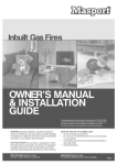
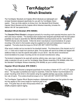
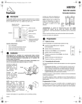
INSTALLATION, OPERATION AND MAINTENANCE MANUAL
MODEL 36DRG
PLEASE READ THIS MANUAL CAREFULLY BEFORE INSTALLING AND OPERATING THE FIREPLACE
THE DELRAY MODEL 36 DRG INSERT IS C.G.A. APPROVED FOR NATURAL GAS AND PROPANE
ALWAYS RETAIN THE MANUAL WITH THE UNIT IN THE EVENT OF A CHANGE OF OWNERSHIP
APPROVED AS A GRAVITY VENTED ROOM HEATER
FOR YOUR SAFETY:
IF YOU SMELL GAS:
1.)
2.)
3.)
4.)
OPEN WINDOWS
DO NOT TOUCH ELECTRICAL SWITCHES
EXTINGUISH ANY OPEN FLAME
IMMEDIATELY CALL YOUR GAS SUPPLIER
DO NOT STORE OR USE ANY
FLAMMABLE VAPOURS OR LIQUIDS
NEAR THIS OR ANY OTHER GASBURNING APPLIANCE.
FOR INSTALLATION IN ACCORDANCE WITH CANADIAN REQUIREMENTS
CERTIFIED TO STANDARD: CAN/CGA 2.22 - M86 VENTED DECORATIVE APPLIANCE
CAN/CGA 2.17 - M91 HIGH ALTITUDE
CAN/CGA 2.1 - M86 ROOM HEATER
CANADIAN HEATING PRODUCTS INC
13120 - 76TH AVENUE, SURREY B.C. V3W 2V6
PHONE (604) 597-3115
FAX: (604) 597-3096
09/96
Page 1 of 11
36DRG
GENERAL INSTRUCTIONS
NOTE: All gas inspection authorities in Canada require that the installation and maintenance of heaters and
accessories shall be accomplished by qualified gas fitters in accordance with the CAN/CGA B149.1 and 2
installation codes and other applicable code requirements specified by the authorities having jurisdiction.
The qualified installer shall instruct the user in the safe and correct operation of this appliance and before leaving the installation, the installer shall ensure that the appliance is in safe working order. Do not remove this
booklet from installation site.
Installation must conform with local codes or, in the absence of local codes, with the current CAN1 -B149
Installation code.
A FAINT ODOUR AND SLIGHT SMOKING WILL LIKELY BE NOTICED WHEN THE FIREPLACE IS
FIRST USED. OPEN A WINDOW UNTIL THE SMOKING STOPS.
The fireplace is not intended to be used as a substitute for a furnace to heat an entire home.
Use for supplemental heating only.
The DelRay Gasfire 36DRG is rated at 28,000 BTUH for Natural Gas and 27,000 BTUH for Propane.
1./ COMBUSTION AIR
A.) In open rooms of normal construction (without
storm windows or tightly fitting doors) sufficient
combustion air can usually be supplied by infiltra
tion. Ensure that the installation location is
adequately ventilated and that the air flow supply
is not subject to obstructions.
B.) Ensure that clearance is maintained around air
opening into combustion chamber.
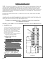
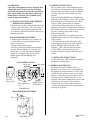
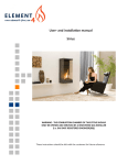
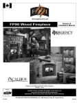
2./ APPLIANCE LOCATION AND
CLEARANCES
10"
8"
A.) Due to high temperatures, the appliance should be
located out of traffic areas and away from furni
ture and draperies ensuring a minimum clearance
of 900 mm (36 inches)
B.) Children and adults should be alerted to the
hazards of high surface temperature and should
stay away to avoid burns or clothing ignition.
C.) Young children should be carefully supervised.
when they are in the same room as the fireplace.
D.) Clothing or other flammable material should NOT
be placed on or near the fireplace.
E.) Minimum side clearances to combustibles:
Side Facing: 1"Perpendicular Wall: 3"
Top Facing: 8" Mantle: 18 1/2" {based
(See Drawing #1)
on 10" shelf depth}
F.) The appliance must be installed in a vented solid
fuel fireplace with a working flue and constructed of a
noncombustible material. (Not for use with air tight
units).
09/96
2 1/2"
8"
Damper
plate
locked in
"Open"
position
26 3/8"
DRAWING #1
Page 2 of 11
36DRG
3./ NATURAL GAS AND PROPANE PIPING
A.) All gas piping shall be in accordance with the
current CAN/CGA B149.1 and .2 installation
codes and installed by a qualified professional
gas fitter technician.
Inlet pressure N/G 7.0 W.C.
Minimum natural gas inlet pressure 5.0" W.C.
Manifold pressure 3.5" W.C.
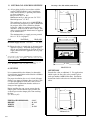
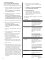
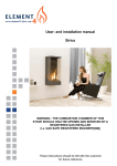
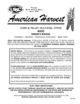
Drawings - #2a, #2b and #2c (with add on)
8"
26 3/8"
21 1/4"
This appliance has been set for 28,000 BTUH at
Sea level rating for natural gas and 27,000 BTUH
for propane and is CGA certified for altitudes
between 0 - 2000 feet without an orifice change
and 2000 - 4500 feet with an orifice change. The
orifice required for high altitude must be supplied
by the manufacturer.
24"
13 5/8"
16 1/8"
DRAWING #2a
The minimum inlet gas supply pressure permissi
ble is 11" W.C. for propane.
28"
17 1/4"
GAS
NATURAL
PROPANE
Manifold Pressure
3.5" W.C.
10.5" W.C.
Minimum Supply Pressure 5.0" W.C.
11" W.C.
B.) Ensure that the gas supply pipe is adequate for the
appliance capacity. A 1/8 inch plugged tapping
must be provided immediately upstream of the gas
supply connection to the appliance for test gauge
connection.
26 3/8"
After gas line is connected, it is a CAN/CGA B149 code Requirement
(Section 8.25.3(e)) that: “each appliance Connection, valve, valve train,
shall be checked while under normal pressure with either a liquid solution
or leak detection device, to locate any source of leak.” Tighten any areas
where bubbling appears or leak is detected until Bubbling stops completely. DO NOT use a flame of any kind to test for leaks.
38 3/16"
DRAWING #2b
4./ VENTING
OFFSET BOX
It is recommended that the chimney be thoroughly
cleaned before installation and checked for soundness
and general condition.
For proper installation, the use of a 4 inch (100 mm)
diameter gas approved chimney liner is needed. This
is to provide appropriate draft and avoid excessive
corrosion In the combustion chamber and heat exchanger of the appliance.
Extends flue collar an additional 3". For applications
which require the flue collar to be extended, please
order part number 36DRG Offset Box. Installation
instructions for this offset box are included with the
offset.
OFFSET BOX
Before installing the vent system, ensure that the
damper plate is locked into the open position and
secured to prevent the damper plate from crushing
the liner.
(See Drawing #1)
11"
26 3/8"
FIREPLACE DIMENSIONS:
HEIGHT:
WIDTH:
DEPTH:
○
○
○
○
○
○
○
○
○
○
○
○
○
○
○
○
○
○
○
○
○
○
○
○
○
○
○
○
○
○
○
○
○
○
○
○
○
○
○
○
○
○
○
○
○
○
21 1/4"
2 3/4"
21 1/4"
28"
13 5/8"
13 5/8"
16 1/8"
DRAWING #2c
09/96
Page 3 of 11
36DRG
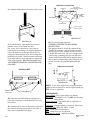
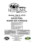
5./ INSERT INSTALLATION
This appliance is to be installed in a masonary or slid
fuel fireplace only. (Not for use with air tight units.)
*Ensure that the plastic protective coating on the
all brass pieces is removed before lighting the
fireplace. Failure to do so will result in permanent
damage to the brass.
Outer
Shell
The brass louvres can be easily removed from the
outer box of the fireplace. We recommend that
they are removed to prevent any damage. The
louvres are held on with spring loaded pins.
1.) Remove the 2 glass panels from the unit to access
the heat exchanger {see section on glass panel removal}.
2.) Detach burner tray by removing the two screws
located on either side of the tray. Pull tray slightly
towards the front of the unit and carefully pull
Burner out.
3.) Unscrew rheostat box and remove
4.) Detach decorative hood by removing the screws
located on each side.
5.) Remove the two screws at the top {left and right
side} of the heat exchanger. Pull heat exchanger,
including refractory, from the outer shell.
6.) Place the outer shell only into the masonary
fireplace. (See Drawing #3a)
Decorative Hood
View of Heat
Exchanger
removed from
outer shell
Heat
Exchanger
DRAWING #3b
7.) To connect the flexible gas liner, detach the
drafthood. Drop the flex liner down in to the
fireplace shell. Secure the flex liner to the flue
collar with a minimum of 2 sheet metal screws.
Flex Liner
Remove to pull out heat exchanger.
DRAWING #3a
Flue Collar
DRAWING #4
09/96
Page 4 of 11
36DRG
RHEOSTAT CONNECTION
(FAN SWITCH)
AUTOMATIC HEAT CONTROL
(100 F)
2 AMP FUSE
8.) Push the drafthood back in to place and re-secure.
BK
BK
BK
VARIABLE
SPEED
CONTROL
WH
STRAIN RELIEF
BK
G
JUNCTION BOX
QUICK CONNECT
PLUG TO MOTOR
BLOWER
BLOWER
MOTOR
DRAWING #5
9.) Level the unit by adjusting the two hex head
machine screws located inside the shell.
For easiest access, adjust these screws prior to
replacing the heat exchanger. If further adjustments
need to be made to level the unit after the heat exchanger has been replaced, locate the levelling bolts
behind the gas control. The Piezo ignitor and mounting bracket will have to be removed to reach the bolt
on the right hand side. BE SURE TO MAKE ALL
ADJUSTMENTS PRIOR TO CONNECTING THE
GAS LINE.
DRAWING #7
12.) Test fan for proper operation.
WARNING: ELECTRICAL GROUNDING
INSTRUCTION:
The appliance must be electrically connected and
grounded in accordance with local codes or, in the
absence of local codes, with the current CSA C22.1
Canadian Electrical Code. The fan is equipped with
a three prong (grounding) plug for your protection
against shock hazard and should be plugged directly
into a properly grounded three prong receptacle. Do
not cut or remove the grounding prong from this
plug.
SCHEMATIC DIAGRAM
FAN BRACKET
G
H
N
FAN SWITCH
FUSE
MOTOR
DRAWING #8
Remove to
access fan
NOTE: If any of the original wire as supplied with the
appliance must be replaced, it must be replaced with type
SEW wire or its equivalent.
Levelling Bolts
10.) Once the outer shell and heat exchanger have
been secured together, re-install the burner tray and
rheostat box.
11.) Connect the fan wires to the rheostat and extend
the electrical cord along the hearth to wall outlet or
direct wire to grounded 120V supply.
09/96
COMPONENTS:
Blower/Motor: Fasco; dual squirrel case blowers
Fan Switch: T-O-D 60T12; 115 V; 60HZ; 100 F setting;
enclosed disk
Wiring (Internal): Type TEW 105C or equivalent; 18
AWG
Connectors: Suitable solderless connectors, CSA Listed
Appliance Cord: Wire Fab; SPT-2; 3 Cond
Plug: 18 Ga (CSA), moulded plug
Fuse: 2 Amp; buss type or equivalent
Pilot Burner & Ignitor: Robertshaw 5SHL2
Page 5 of 11
36DRG
13.) a) Operating the fan:
The fan speed can be controlled by turning the
variable speed control clockwise to slow the fan
down and counterclockwise to speed it up.
There is a built-in automatic heat control that will
Activate when the fireplace has reached (100 F)
temperature. The fan will not operate when the
fireplace is cold.
b)Removing fan assembly for servicing:
Remove the (3) screws located on each side wing
of the fan bracket. Remove the (3) screws
located on the base of the bracket. Back out
the (2) levelling bolts also located on the box.
Remove. (See Drawing #6)
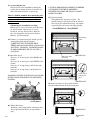
CAUTION: IMPROPER PLACEMENT OF EMBERS
COULD RESULT IN THE FLAME BEING
DIVERTED TOWARDS THE GLASS CAUSING
MARKS TO FORM
17.) Glass Placement:
This appliance has two pieces of glass. The
smaller sized glass will be placed on the unit first.
Place top of glass behind metal strip. Set bottom
of glass in place and secure with clips provided.
GLASS REMOVAL / PLACEMENT
Inside Piece
Only
14.) Connect gas to burner using the flexible gas line
extension provided with the fireplace.
CAREFULLY TEST TO ENSURE THAT
THERE ARE NO LEAKS USING A SOAP SUDS
SOLUTION. UNDER NO CONDITION SHALL
FLAME OR FIRE BE USED TO LOCATE A
GAS LEAK.
15.) Install the log set:
Place log “A” on the log rest at the REAR of the
firebox.
Place log “B” on the log rest at the FRONT of the
firebox.
Place log “C” on top of logs A & B on the right
hand side.
Place log “D” on top of logs A & B on the left
hand side.
WARNING: FAILURE TO INSTALL LOGS AS PER
INSTRUCTIONS WILL RESULT IN EXCESSIVE
SOOTING.
D
C
A
Slide glass under
metal strip
DRAWING #9a
Secure clips to
hold glass in
place
DRAWING #9b
Mount the front piece of glass on the brackets
Provided underneath the decorative hood piece.
B
Glowing Embers
16.) Ember Placement:
Distribute evenly alongside the front burner only.
Do not pile material directly on top of burner
ports.
09/96
DRAWING #9c
Page 6 of 11
36DRG
6./ OPERATION
"For safety, this appliance has been equipped with
a high limit switch. In the event of over heating,
this switch will automatically turn the unit down to
pilot. Upon cooling, the main burner will re-light.
If this switch is activated, call a qualified service
person to inspect the fireplace."
A./ TESTING, ADJUSTING AND CHECKING
BURNER AND CONTROLS
Light burner by carefully following instructions for
starting given in this manual. Test and adjust all
controls under actual operating conditions and
in accordance with local installation codes for gas
bBurning appliances.
B./ PILOT BURNER ADJUSTMENT
1./ Remove pilot adjustment cap {see figure 10}
2./ Adjust pilot key to provide properly sized
flame {see figure 11}
3./ Replace pilot adjustment cap
4./ Leak test with soap solution after installing or
servicing with main burner on. Coat pipe and
tubing joints etc. with soap solution. Bubbles
indicate leaks. Tighten any areas where the
bubbles appear until the bubbling stops
completely.
GAS CONTROL VALVE
Power Pile
High Limit
1/8 N.P.T.
Pressure Tap
Pilot Adjustment
Cap
On/Off Switch
on Backplate
DRAWING #10
C./ LIGHTING INSTRUCTIONS
The gas control valve is located behind the brass
trim at the base of the fireplace. Before lighting
the pilot, make sure that the gas line is connected
and the gas shut-off valve is turned to the ON
position.
a.)Be sure that the ON/OFF switch located on the
right side of the backplate is in the “OFF” position
b.) Partially depress and turn dial on gas control
Valve to “OFF” position and wait 5 minutes
c.) Turn dial to pilot position, depress dial and
light pilot using red Piezo ignitor button. Hold dial
for 1 minute, then release. If pilot does not remain
lit, repeat, allowing a longer time to lapse
before releasing dial.
d.) Once the pilot has been established, turn the
ON/OFF switch on the side of the backplate to the
"ON" position.
e.) To light the main burner, turn dial to “ON”
f.) Main burner function may now be controlled
with the ON/OFF switch on the side of the
backplate. “OFF” turns the unit back to pilot.
g.) The “HI/LO” dial located on the valve
manually controls the height of the flame on the
burner.
D./ SHUT DOWN INSTRUCTIONS:
a.) Turn knob to the “OFF” position to extinguish
main burner and pilot flame
7./ GENERAL MAINTENANCE
Installation and repairs should be done by a
qualified service person. It is recommended that
the appliance be inspected before use and at least
annually by a professional service person. More
frequent cleaning may be required due to excessive
lint from carpeting, bedding material etc. It is
imperative that control compartments, burners and
circulating air passageways of the fireplace
be kept clean. Any safety guards removed for
servicing this appliance must be replaced prior to
operating the appliance.
PILOT BURNER ADJUSTMENT
3/8" to 1/2"
09/96
DRAWING #11
Page 7 of 11
36DRG
CLEANING PROCEDURE
{GLASS AND BURNER COMPARTMENT}
Periodic cleaning of the glass will be necessary.
Frequency of cleaning will depend on fireplace usage.
a.) Turn the control knob to the “OFF” position. This
will extinguish the flame and allow the unit to
cool.
DO NOT ATTEMPT TO CLEAN THE FIREPLACE WHEN IT IS HOT!
b.) Carefully remove glass pieces. Use caution as
glass edges may be sharp
NOTE: IN CASE OF BROKEN GLASS, REPLACEMENT GLASS MUST BE SUPPLIED BY
CANADIAN HEATING PRODUCTS INC. OR
THE DEALER/DISTRIBUTOR IN YOUR AREA.
i.) Keep appliance area clear of combustible
materials, gasoline and other flammable vapours
and liquids.
j.) WARNING: DO NOT BURN RUBBISH OF
ANY KIND IN THIS APPLIANCE.
8./ TROUBLE SHOOTING
If the fireplace fails to light or appears to be
operating abnormally, do not tamper with it.
Contact a licensed service person, the dealer or
distributor in your area.
To identify the problem with appliance, you can check
the following:
PROBLEM
CORRECTIVE ACTION
Noisy pilot flame
Remove pilot adjuster cap
located next to the gas shut off
valve. Flame is decreased by
turning adjustment screw
clockwise.
Pilot won't ignite
Make sure that the wire at the
back of the Piezo ignitor button
is properly attached. Push the
igniter button several times,
holding in gas control valve
knob.
c.) Be sure to use a non-abrasive cleaner on the glass.
d.) Remove the logs and vacuum thoroughly in and
around burner compartment.
NOTE: WHEN CLEANING BURNERS,
ALWAYS ENSURE THE GAS HAS BEEN
SHUT OFF
e.) Logs may be cleaned periodically with soap and
water
f.) Prior to replacing the logs, relight the pilot and
start the main burner.
1.) Check to see that all burner ports are burning
2.) Check to see that the pilot flame is large
enough to engulf the thermopile
3.) Check to see that the main burner ignites
instantaneously on all ports when the valve
has been turned on
4.) When these checks have been completed, shut
down the burner and pilot and reinstall the logs
If pilot still will not ignite,
remove glass panel and the logs
and try lighting pilot with a
match. If pilot now lights then
the piezo igniter is faulty.
Main burner will
not light
Make sure burner switch is on
(ON/OFF switch on side of
backplate).
g.) Replace the glass
h.) Check periodically that the vent system is unrestricted and a proper draft is present when the unit
is in operation. All vented appliances require a
source of fresh air in order to vent properly.
Recent trends in home improvement and new
tighter construction techniques have contributed to
problems with chimney venting properly. If you
suspect your fireplace is not venting properly, do
not operate the appliance. Seek advice from a
qualified professional to determine the cause of
the problem and find a solution before restarting
the appliance.
09/96
Make sure valve control knob is
in the "ON" position.
Check for loose wire connection
at the gas valve. NOTE: this is
a sensitive millivolt circuit and
the pilot or burner will go out if
terminals are loose or acciden
tally grounded.
Flame Cycles
High limit switch is activating.
Vent Blocked: Clear flue
passage
Severe Downdraft
Check combustion air supply
source of energy causing a
negative condition within the
home.
Page 8 of 11
36DRG
FOR YOUR SAFETY: IF YOU SMELL GAS, OPEN WINDOWS - DON'T TOUCH ELECTRICAL
SWITCHES, EXTINGUISH ANY OPEN FLAME - IMMEDIATELY CALL YOUR GAS SUPPLIER.
NOTE: THIS GUIDE IS MERELY A MEANS OF IDENTIFYING THE PROBLEM AND ITS PROBABLE
CAUSE. REPAIRS SHOULD BE DONE BY A QUALIFIED SERVICE PERSON.
ALL PARTS ARE AVAILABLE FROM CANADIAN HEATING PRODUCTS INC. OR YOUR LOCAL
DEALER/DISTRIBUTOR.
09/96
Page 9 of 11
36DRG
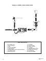
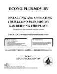
DELRAY GASFIRE 36 DRG SPARE PARTS
11.
10.
9.
16. Pilot Burner Assembly
11.
8.
12.
6.
7.
5.
1.
2.
14.
4.
2.
3.
13.
15.
PARTS DESCRIPTION
1.
2.
3.
4.
5.
6.
7.
8.
09/96
Gas Control Valve
48FF-6 Connector
Union
90 degree Steet Elbow
Compression Nut
1621410 3500125C CH-1 Compression Spring
3/4" ID Flat Washer
Silicon Sponge Seal
9.
10.
11.
12.
13.
14.
15.
16.
3/8" Nipple
G09 Brass Orifice
Primary Air Mixer
3/8" Nipple
CHP-005 Bulk Head Union
Flexible Metal Connector
81-4N Pilot Nut
Robertshaw 5SHL2
Page 10 of 11
36DRG
DELRAY GASFIRE 36DRG
GAS FIREPLACE WARRANTY
THE WARRANTY
The Companies warrants the Montigo Gas Appliance to be free from defects in materials and workmanship at the time of manufacture. On the
Montigo, there is a ten-year warranty on the firebox and its components, a five-year warranty on the main burner, pilot burner and a one-year
warranty on the gas control valve and glass doors.
REMEDY AND EXCLUSIONS
The coverage of this Warranty is limited to all components of the Gas Appliance manufactured by The Companies.
This Warranty only covers Montigo Gas Appliances installed in the United States or Canada.
If the components of the Gas Appliance covered by this Warranty are found to be defective within the time frame stated (see The Companies right of
investigation outlined below). The Companies will, at its option, replace or repair defective components of the Gas Appliance manufactured by The
Companies at no charge, and will also pay for reasonable labour costs incurred in replacing or repairing components. If repair or replacement is not
commercially practical, The Companies will, at its option, refund the purchase price of the Montigo Gas Appliance.
This Warranty covers only parts and labour as provided above. In no case shall The Companies be responsible for materials, components,
or construction which are not manufactured or supplied by The Companies, or for the labour necessary to install, repair or remove such materials,
components or construction. All replacement or repair components will be shipped F.O.B. the nearest The Companies factory.
QUALIFICATIONS TO THE WARRANTY
The Gas Appliance Warranty outlined above is further subject to the following qualifications:
(1) The Gas Appliance must be installed in accordance with The Companies installation instructions and local building codes. The Warranty
on this Montigo Gas Appliance covers only the component parts manufactured by The Companies. The use of components manufactured by
others with this Montigo Gas Appliance could create serious safety hazards, may result in the denial of certification by recognized national
safety agencies, and could be in violation of local building codes. This warranty does not cover any damages occurring from the use of any components
not manufactured or supplied by The Companies
(2)The Montigo Gas Appliance must be subjected to normal use. The Gas Appliances are designed to burn gas only.
Burning conventional fireplace fuels such as wood, coal or any other solid fuel will cause damage to the Gas Appliance, will produce
excessive temperatures and will result in a fire hazard.
LIMITATIONS ON LIABILITY
It is expressly agreed and understood that The Companies sole obligation, and purchaser's exclusive remedy under this
Warranty, under any other warranty, expressed or implied, or in contract, tort or otherwise, shall be limited to replacement, repair, or
refund, as specified above.
In no event shall The Companies be responsible for any incidental or consequential damages caused by defects in its prod ucts, whether such
damage occurs or is discovered before or after replacement or repair, and whether or not such damage is caused by The Companies negligence.
Some states do not allow the exclusion or limitation of incidental or consequential damages, so the above limitation or exclusion may not apply
to you. The duration of any implied warranty with respect to this Montigo Wall Furnace is limited to the duration of the foregoing
warranty. Some states do not allow limitation on how long an implied warranty lasts, so the above may not apply to you.
INVESTIGATION OF CLAIMS AGAINST WARRANTY
The Companies reserves the right to investigate any and all claims against this Warranty and to decide upon method of settlement.
THE COMPANIES ARE NOT RESPONSIBLE FOR WORK DONE WITHOUT WRITTEN CONSENT
The Companies shall in no event be responsible for any warranty work done without first obtaining The Companies written consent.
DEALERS HAVE NO AUTHORITY TO ALTER THIS WARRANTY
The Companies employees and dealers have no authority to make any warranties nor to authorize any remedies in addition to or
inconsistent with those stated above.
HOW TO REGISTER A CLAIM AGAINST WARRANTY
In order for any claim under this Warranty to be valid, The Companies must be notified of the claimed defect in writing or by telephone, as
soon as reasonably possible after the defect is discovered. Claims against this Warranty in writing should include the date of installation, and a descrip
tion of the defect.
OTHER RIGHTS
This Warranty gives you specific legal rights, and you may also have other rights which vary from state to state.
NOTE: The Companies as stated above refer to - Canadian Heating Products Inc. and/or Montigo Del Ray Corp.
Canadian Heating Products Inc. and/or Montigo DelRay Corp. reserves the right to make changes at any time, without notice, in design,
materials, specifications, prices and also to discontinue colors, styles and products.
MONTIGO DEL RAY CORP.
6925 Salashan Parkway, Ferndale, WA 98248
Tel: (206) 366-3507 Fax: (206) 366-1054
09/96
CANADIAN HEATING PRODUCTS INC.
13120 76th Avenue, Surrey, B.C. Canada V3W 2V6
Telephone
(604) 597-3115
Fax
(604) 597-3096
Page 11 of 11
36DRG