1
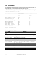
4.15 System Alarms
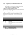
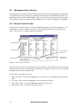
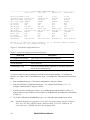
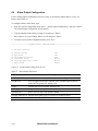
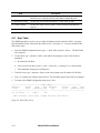
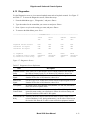
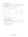
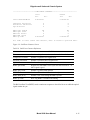
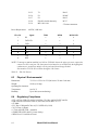
The System Alarms screen reports alarms and faults on the local 2340 and the remote 2340. See
Figure 20 and Table 19. To view current alarm status, follow these steps:
1. From the Main Menu, type 5, Alarms, and press <Enter>. The System Alarms report appears.
2. To return to the Main Menu, press <Esc>.
------------------------------SYSTEM ALARMS-------------------------------
Modem Redundancy Status
Configuration Errors
Fiber Loss of Signal
Electrical Loss of Signal
SQL Rx
Chassis Management
Alarm Relay Inputs
Power Supply Primary
Power Supply Secondary
Fan
Power-On Self Test
Local
Remote
N/A
No
No
No
OK
N/A
N/A
OK
N/A
N/A
OK
N/A
No
No
No
OK
N/A
N/A
OK
N/A
N/A
OK
Figure 20. System Alarms Screen
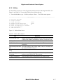
Table 19. System Alarms Definitions
Item
Definition
Modem Redundancy
Status
Reports if redundancy is Active, Inactive, or turned off (N/A)
Configuration Errors
Check that the local and remote modems have compatible set ups,
including software version
Fiber Loss of Signal
Checks if optical loss of signal errors
Electrical Loss of Signal When LOS detection is On, checks if electrical loss of signal occurs
SQL Rx
Checks if squelch occurs
Chassis Management
Reports OK if 2340 is in UCS 1000 with DMM or N/A if 2340 is in
1040, 1050, or UCS 1001
Alarm Relay Inputs
Reports Loss if CLS occurs or OK if signal is good; UCS 1001, only
Power Supply Primary
Reports function of main power supply
Power Supply Secondary Reports function of second power supply
Fan
Reports fan failure
Power-On Self Test
Reports OK or faulty hardware or software
4-16
Model 2340 User Manual