1
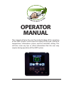
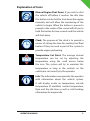
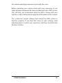
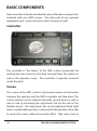
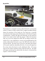
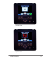
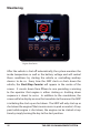
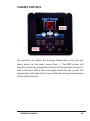
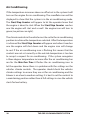
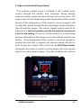
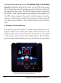
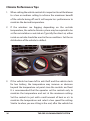
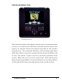
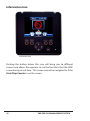
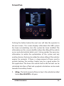
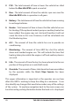
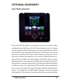
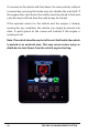
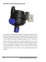
OPERATOR
MANUAL
This manual will give the user the understanding of the operation
of the GRIP System. It will cover the setting of the time, control of
temperature, information system, and the anti-theft setting. This
will also cover any tips or other information that the user may
require during operation of the GRIP System.
The following information is subject to change without notice and
there may be slight differences in how the system functions on
different types of vehicles. To access the latest version of this manual
please refer to the website or contact info located on the back cover
of this manual.
The QR code located on the front cover can be used to access the
Operator video to provide the basic knowledge for operating a
vehicle that is equipped with the grip system. The quick start guide
at the front of this manual will also provide the basic knowledge
required. However it is recommended for the operator to read the
complete Operators manual to fully understand its functions.
02-13
THE GRIP IDLE MANAGEMENT SYSTEM
Table of Contents
Quick Start Guide
Introduction ..................................................................... 1
Description of Icons ................................................... 2-5
Sequence of Operation ......................................... 6-10
Information .............................................................. 11-14
Grip System Settings ............................................ 15-18
Operators Manual
Introduction .................................................................. 19
Basic Components ...................................................... 21
Initial Start and Stop.................................................... 25
Monitoring ..................................................................... 27
Climate Control ............................................................ 28
Air Conditioning .......................................................... 29
Heating ........................................................................... 31
Climate Performance Tips ........................................ 35
Low Battery .................................................................... 37
Programming the Clock ............................................ 41
Engine Stop Button .................................................... 43
Hood Open Icon .......................................................... 44
Communications Icon ............................................... 46
Information Button ..................................................... 47
Optional Equipment
Anti Theft ........................................................................ 52
Solenoid .......................................................................... 54
Coolant Pump ............................................................... 55
Auxiliary Heater ........................................................... 56
Engine Preheating ....................................................... 57
Heater Remote Start ................................................... 61
Audible Alarm ............................................................... 62
Current Sensor .............................................................. 63
Servicing the Vehicle ............................................... 65
Frequently Asked Questions................................ 67
Basic Troubleshooting ............................................ 70
OPERATOR MANUAL
QUICK START
The GRIP Idle management system is designed to control the
vehicle engine to reduce idling yet maintain a comfortable work
environment for the operator. It is designed to maintain electrical
power required for computers, lighting and other systems added to
the vehicle. It acts as a link between the equipment and the vehicle
and provides necessary information for the operator. The system
simply controls the vehicle ignition the same way the operator
would. It cycles the key in the run, start and accessory positions
as required. The GRIP idle management system has many different
functions and can control auxiliary equipment if they are added as
an option.
The following Operator Handbook outlines the different functions
and communications that you may see on your vehicle during the
operation. The GRIP system only operates when the vehicle is in
Park or Neutral. The following procedures will outline what you can
expect to see when the vehicle is in park and the engine is at idle.
The icons shown on the screen are identified in the following pages
for your reference throughout this manual.
1
THE GRIP IDLE MANAGEMENT SYSTEM
Explanation of Icons
Manual Engine Shut Down: If you wish to shut
the vehicle off before it reaches the idle time
this button can be held to shut down the engine
manually and will allow the monitoring of the
vehicle to begin. When the button is pressed a
prompt in the center of the screen will tell you to
hold the button for two seconds and the vehicle
will shut down.
Clock: The purpose of the clock is to provide a
means of setting the time for auxiliary fuel fired
heaters if they are used as part of the system to
provide engine preheating.
Temperature Set Point: The average desired
temperature can be set by adjusting the
temperature using the scroll arrows below
the icon. The system will try to maintain this
temperature as long as the controls on the
vehicle are set correctly by the operator.
Info: The information area provides the operator
with information about the vehicle system.
It will display inside air temperature, outside
temperature (if available) coolant temperature,
Rpm and the idle time as well as vital tracking
information for engine idle.
OPERATOR MANUAL
2
Anti-Theft: This is an optional feature that allows
the operator to press this button and remove the
keys and the engine will continue to run. Once
the engine has reached the max idle time the
engine will shut down and enter the monitoring
phase. This will allow the operator to leave
the vehicle unattended and secure it with the
vehicle security system. If someone tries to steal
the vehicle, it will shut down.
Engine Running Status: This icon is displayed
any time that the vehicle engine is running
while in Park or Neutral to allow the operator to
quickly glance at the screen to see the status of
the engine. If the engine is running there is no
delay in putting the vehicle in drive.
Engine Off Status: This icon will be displayed
any time the vehicle is in Park or Neutral and
the engine is off. This will allow the operator to
quickly glance at the screen and realize that he
must turn the key forward to the start position to
start the engine before putting into drive.
Start/Stop Counter: The counter is displayed
when the vehicle engine is being shut down or
started so the operator is aware of the vehicle
engine condition. When the idle time reaches 15
seconds before shut down the counter comes
on to count down from 15 to 1 and then the
engine stops or starts. An audible alarm option is
available to coincide with the counter. The alarm
has different tones for starting and stopping.
3
THE GRIP IDLE MANAGEMENT SYSTEM
Low Battery Start: The red battery icon will be
displayed whenever the battery condition has
reached the settings for low battery. At this time
the counter will be displayed to tell the operator
that the engine is starting for low battery.
Low Battery Run: This icon is displayed to
show the operator that the reason the engine
is running is to charge the batteries. The engine
will run for a period of time determined in the
system settings.
Air Conditioning: This icon will be displayed
if the vehicle is starting or is running for air
conditioning. The settings of the vehicle must
be set to A/C by the operator for the cab to
cool. If the vehicle settings are incorrectly set to
heat and the temperature actually climbs in the
cab, the air conditioning icon will flash and the
engine will shut down. Set the controls to A/C
and the system will reset after the vehicle has
been started manually.
Heating: When the vehicle requires heat the
icon will come on when it is starting the vehicle
as well as while the engine is running. If the
system has a coolant pump option installed the
icon will remain on when the vehicle shuts off
and the pump continues to function. The vehicle
will restart when the coolant temperature drops
to 45oC. If an auxiliary fuel fired heater option is
used, the heater simply replaces the engine to
provide heat. The pump will continue to operate
OPERATOR MANUAL
4
as usual and if the coolant temperature drops to
60oC the heater will start up to produce heat.
Loss of Communication (WARNING): This icon
will be displayed in the center of the screen if the
system has lost communication with the vehicle.
A service representative should be contacted
immediately. It is not recommended for the
vehicle to be driven until this has been resolved.
Hood Open (WARNING): This icon will be
displayed any time the hood is open and the
keys are in the ignition, or the vehicle is in anti
theft mode. The hood pin is installed to ensure
that the vehicle does not start automatically for
technicians. The technicians should be sure that
the icon is on if they are leaving the keys in the
ignition while servicing to ensure their safety.
The engine may be started or stopped by the
key as usual but it will not start or shut down
automatically. A service representative should be
contacted immediately. It is not recommended
for the vehicle to be driven until this has been
resolved.
5
THE GRIP IDLE MANAGEMENT SYSTEM
SEQUENCE OF OPERATION
Engine Shut Down
Figure 1: The Main Screen will show
that the engine is running and will
display the day and time, engine
status icon, manual engine shut
down icon, clock icon, temperature
set point, info and anti theft icon(if
option is selected).
Figure 1
Figure 2: When the Max Idle Time
is reached the engine Start/Stop
Counter will be displayed and the
engine will shut down after the
15 second count. If the audible
alarm option is used, the alarm will
provide two quick beeps for every
second on the counter.
Figure 3 (Engine Off): When the
Max Idle Time is reached the Start/
Stop Counter will be displayed and
the engine will shut down and the
Engine Off Status will be displayed.
To restart the vehicle simply turn the
key to the start position. The system
is now in the Monitoring phase.
Figure 2
Figure 3
OPERATOR MANUAL
6
Engine Starting for A/C
Figure 4: If air conditioning is
required, the A/C icon will be
displayed and the Start/Stop
Counter will begin counting down
to one before engine start. If the
audible alarm option is installed a
single beep for every second on the
counter will be heard. The controls
for the climate of the vehicle must
be in the air conditioning position
for this function to work.
Figure 4
Figure 5: Once the engine has
started, the Engine Running Status
icon will be displayed and the Air
Conditioning icon will remain on.
Figure 6 (Engine Off): When the
set point temperature is reached
the Start/Stop Counter will be
displayed and the engine will shut
down. The Engine Off Status Icon
will be displayed. The system goes
back into the Monitoring phase.
Figure 5
Figure 6
7
THE GRIP IDLE MANAGEMENT SYSTEM
Heating
Figure 7: If heat is required the Start/
Stop Counter will begin counting to
one to tell the operator the engine
is going to start. If the audible alarm
option is installed a single beep for
every second on the counter will be
heard. The controls for the climate of
the vehicle must be in the heating
position for this function to work.
Figure 7
Figure 8: Once the engine has
started, the Engine Running Status
icon will be displayed and the
Heating icon will remain on.
Figure 9 (Engine Off): For vehicles
with the auxiliary coolant pump
option the engine will start and
bring the coolant temperature
to 75oC and the engine will shut
down and the pump will continue
to operate until the coolant reaches
45oC and it will need to restart the
engine again. For vehicles with the
auxiliary fuel fired heater option the
engine will not start at all to provide
heat. The auxiliary heater will keep
the coolant temperature above 60oC
and the coolant pump will continue
to operate pumping the hot coolant
into the cab.
OPERATOR MANUAL
Figure 8
Figure 9
8
Low Battery Starting
Figure 10: If the battery level
becomes low, the Low Battery
Start icon will be displayed and the
Start/Stop Counter will begin and
the engine will start.
Figure 11: Once the engine has
started, the Engine Running Status
icon will be displayed and the Low
Battery Run icon will be displayed.
The engine will remain running for
a predetermined time set in the
management settings of the screen.
Figure 12: Engine Off: Once the Max
Run Time is reached the system will
display the Start/Stop icon and the
engine will shut down. The system
will then go back into monitoring
mode. If the Current Sensor option
is installed and there is a load greater
than 37.5 amps at 12VDC the
engine will not shut down. Once the
load has been removed the system
will then go into the Max Run Time
again to further charge the batteries
after using them to power the loads.
A typical application for this would
be using a DC to AC inverter to
power electrical tools.
9
Figure 10
Figure 11
Figure 12
THE GRIP IDLE MANAGEMENT SYSTEM
Low Battery At Start Up: If the vehicle has been parked for over
72 hours or the vehicle battery has been depleted to less than 11.0
volts the GRIP controller will shut itself off completely. When the
operator arrives at the vehicle the keys must be turned to the run
position and allow the controller to turn back on before the vehicle
will be able to start. Once the screen is back on to the main screen
the system is ready. Do not turn the ignition to the start position
at this time or it will delay the starting of the controller and you
will have to turn the keys back to accessory and then to run. This
feature is to reduce the chance of the vehicle not starting. As long as
the battery can maintain above 8.5 volts the controller will turn on
and activate the solenoid to connect the auxiliary battery and the
vehicle will start. After this condition the clock will need to be set as
the information will be lost.
OPERATOR MANUAL
10
INFORMATION
Figure 13
Figure 13:
Battery Voltage: The system has the ability to monitor two battery
banks installed on the vehicle but both batteries are joined together
in certain conditions. When the vehicle is started and the vehicle
is running all batteries are connected together. When the engine
is shut off the batteries become separated and the vehicle battery
sustains the system until the voltage drops to a certain threshold
at which time the second battery bank is connected. Once the two
battery banks reach a new setting the vehicle will start to charge
the batteries.
Vehicle RPM: This is taken from the vehicle communication system
to determine the engine status.
11
THE GRIP IDLE MANAGEMENT SYSTEM
Coolant Temperature: Supplied by the vehicle communications
network this information is used to allow the GRIP system to control
the heating of the coolant for operator comfort.
INT: The interior temperature is provided by a sensor that has been
installed to read the temperature of the cab for controlling the cab
temperature.
EXT: The exterior temperature is received from the vehicle
communication if it is available. If the information is not available it
will have n/a as a value.
Idle Time: The idle time is a count in seconds of how much time the
vehicle has been in Park or Neutral and the engine idling.
OPERATOR MANUAL
12
Figure 14
Figure 14:
Idling: The Total amount of time in hours that the vehicle has idled
below Max Idle RPM in all gears.
P/N: The total amount of time in hours that the vehicle has idled
below the Max Idle RPM in park and neutral.
Run: Total amount of time the engine has been running above idle.
Battery: Total amount of engine hours required to charge the
batteries during monitoring.
Heater: Total time in hours the engine has run for heating. If the
vehicle is equipped with a coolant pump or auxiliary heater this will
not include the time of operation of the auxiliary devices.
A/C: Total hours that the engine has run for air conditioning.
13
THE GRIP IDLE MANAGEMENT SYSTEM
Monitor: This is the total amount of time that the engine has been
off and just waiting to provide something where as normally the
engine would be running. This will include time that auxiliary
heaters or coolant pumps are providing heat as long as the engine
is not running.
Life: The life is calculated by the time that the key is in the vehicle
ignition including anti theft to the time where the keys are out of
the vehicle.
Override: The override shows the amount of times that vehicle shut
down has been avoided by the operator pressing the accelerator
before the engine shuts down for idle.
OPERATOR MANUAL
14
GRIP SYSTEM SETTINGS
Changing the Clock
Figure 15: Press the button below
the clock icon to access the clock
area. If an auxiliary fuel fired heater
is installed and the seven day timer
option has been selected the screen
will prompt you to choose the clock
or the heater setting. If the heater
is not selected it will direct you
directly to the clock. (Figure 16)
Figure 16: The clock is required
to be set for the auxiliary fuel fired
heater option to be able to preheat
the vehicle engine. Press the SET
DAY, SET HOUR or SET MINUTE
button and the triangles above and
below will turn orange allowing
you to adjust the setting by using
the scroll button with the arrows
up and down. Once completed use
the back button to reach the main
screen.
Figure 17: The seven day timer is
set similar to the clock for setting.
Once the timer is set, you must
push the OK button to activate and
the on icon will turn green as seen
in Figure 17. The heater will run for
15
Figure 15
Figure 16
Figure 17
THE GRIP IDLE MANAGEMENT SYSTEM
a maximum of 90 minutes so the time you set in the heater timer
should be 60-90 minutes before you wish to start the vehicle. It is
better to have the heater still running when you are ready to start
the vehicle to retain as much heat as possible as opposed to the
heater being off for several minutes before starting. When you start
the vehicle and the heater is still running, the system will check the
coolant temperature of the vehicle and If the coolant temperature
has not reached 75oC the heater will continue to operate even while
the vehicle is being driven. If the key is left in the ignition, the heater
will not start by the timer. To ensure that the heater does not start in
a building the keys should be left in the ignition in the off position
and the heater will not start. (For heavy duty applications the timer
must be shut down as we can not see when the key is slid into the
ignition).
Setting the Temperature
Figure 18: To set the temperature simply use the scroll button with
arrows up and down to adjust. The high and low limits are adjusted
in the management settings upon installation.
Figure 18
OPERATOR MANUAL
16
Anti-Theft
Figure 19: The anti theft function
allows the operator to remove
the keys without shutting off the
engine. The doors can be locked
and the vehicle security system
activated to deter theft of the
vehicle. If the vehicle were accessed
and the assailant pulls the vehicle
into drive the engine will stall and
the key must be placed into the
ignition in order to de activate
the anti theft option. (note: on
heavy duty vehicles the key must
be turned to the run position to
deactivate the anti theft)
Figure 20: Press the anti theft
button to engage. It can also be
activated on traditional switchplex’s
used for vehicle lighting etc. if
equipped. The icon will turn green
when the anti theft is activated.
Figure 21: If the engine is off the
anti theft can still be activated to
keep systems monitoring while the
operator is away from the vehicle.
When the anti theft is engaged, the
key position will cycle to accessory
rather than run if no heat is required
17
Figure 19
Figure 20
Figure 21
THE GRIP IDLE MANAGEMENT SYSTEM
to conserve power. If the requirement for heat presents itself it will
automatically cycle back to run. When the ignition is switched to
accessory some functions such as windows etc will not be accessible
so it is not recommended if the operator is in the vehicle to use the
anti theft.
To disengage the anti theft slide the keys into the ignition and turn
to the run position and the anti theft is immediately turned off. If
the keys are put into the ignition but not turned to run the anti theft
will disengage in 5 seconds and the vehicle will shut off. The keys
will have to be pulled out and cycled to run and then off before the
vehicle will start. The anti theft can also be disengaged by pressing
the anti theft button on the screen. The icon will turn white to show
the operator that the anti theft is off.
OPERATOR MANUAL
18
INTRODUCTION
The GRIP Idle Management System has been installed to manage
the time that the vehicle spends operating in idle. This system not
only saves fuel, excessive wear, extends vehicle life, it is also a benefit
to the environment reducing emissions caused by unnecessary idle.
The GRIP system works in conjunction with the vehicles CAN
(Controller Area Network). It receives real time data on the vehicles
functions including engine revolutions, transmission position,
outside temperature, ignition positions and coolant temperature.
Other data required by the GRIP system is received through sensors
added when the system is installed in the vehicle. The controller
of the system then makes decisions based on the information it
receives allowing it to start and stop the engine of the vehicle as
required.
The GRIP controller will only control the vehicle engine’s ability to
start and stop when the vehicles transmission is in the park or neutral
position. The vehicle will not shut down when stopped in traffic, at
a stop sign or traffic light provided the vehicles transmission is not
put into the park or neutral position.
One of the unique features of this system is that input from the
operator is also vital to the operation of the system. The operator has
the ability to control the climate inside the vehicle to their desired
average temperature with a simple push of a button. Since the GRIP
system monitors batteries and auxiliary optional equipment as
well, it allows the operator to perform all tasks as usual. The only
difference being the vehicle will be shut down for unnecessary idle
without compromising the operators function ability, comfort or
safety. The GRIP system doesn’t just simply shut down your vehicle
when it idles; it has been designed with the user in mind keeping
19
THE GRIP IDLE MANAGEMENT SYSTEM
the vehicle operating experience practically the same.
Before operating your vehicle check with your supervisor to see
what optional equipment has been installed with your GRIP system.
This will help you understand what the GRIP is doing with your
vehicle as well as being able to apply the information in this manual.
The system has several settings that control the GRIP system to
function properly. If you feel that some of your settings need
adjusting please contact your supervisor and they can determine
the best solution.
OPERATOR MANUAL
20
BASIC COMPONENTS
Take some time to locate and identify some of the basic components
included with your GRIP system. Also take note of any optional
equipment your system may have and its location as well.
Controller
The controller is “the brains” of the GRIP system responsible for
making decisions based on the data received from the vehicle as
well as the operators input. The controller is typically mounted
under the dash.
Screen
The screen of the GRIP system is the location where all interaction
between the operator and the GRIPs controller will take place. The
screen position can be adjusted manually up and down as well as
side to side by loosening the adjustment tab on the side of the
flexible mount. The adjustment tab can be tightened hand tight
when a comfortable position is achieved for the operator to be able
to reach the screen without too much effort. Take some time to
21
THE GRIP IDLE MANAGEMENT SYSTEM
get to know what all the icons that are represented on the screen
as it will allow you to understand the GRIP systems functions and
make user adjustments more convenient. This can be found in the
quick start section. This is the component that allows the operator
to set the temperature and the clock as well as control some of the
functions that the GRIP monitors. Consequently this is also the area
the GRIP system communicates the functions it is performing as
well as showing the operator the real time functions it is monitoring
as well. The screen is only accessible when the vehicle is in park
or neutral, when you are driving down the road the screen will be
blank. This important safety feature insures it will not be a driving
distraction for the operator.
OPERATOR MANUAL
22
Hood Pin
The hood pin is a magnetic sensing safety feature for servicing the
vehicle. It needs to make contact with a magnet installed directly
above the position of the hood pin. The hood pin is typically
mounted near the hinge point of the hood or at the front of engine
compartment. A yellow led light will illuminate on the hood pin
when it has made contact with the magnet. When the hood pin
does not sense the magnet the GRIP will no longer monitor the
vehicle. This is very important as service can be performed on the
vehicle safely when the hood is up as the GRIP will not be able to
start the vehicle. The only way to start up or shut down the engine
at this point would be manually with a key. An icon will appear on
the screen when the hood is up for additional safety. All service
work on the vehicle should be done with the hood up. The GRIP
will begin monitoring the vehicle after the hood is closed and the
engine is started manually.
23
THE GRIP IDLE MANAGEMENT SYSTEM
CAN Connection
This connection is where the GRIP controller reads the vehicle
information necessary to make decisions for starting and stopping
the engine. The connection is made into the existing OBD connector
and is typically found on the driver side of the vehicle near the gas
and brake pedals.
Temperature Sensor
The temperature sensor is how the GRIP reads the interior
temperature of the vehicle cabin. It is typically mounted on the
dash of the vehicle out of the path of vents or direct sunlight to
ensure accurate readings.
Fuses
The fuses are for the GRIP controller as well as the optional
auxiliary heater are typically located near the battery in the engine
compartment or connected to the solenoid if auxiliary batteries are
being used. The GRIP uses a 10 amp mini fuse.
OPERATOR MANUAL
24
OPERATION
Initial Start and Stop
Initial Start Up Screen
When the vehicle is started, a green engine icon will appear in the
center of the screen identifying that the engine is running. When
the vehicle reaches the Max Idle RPM specified in the controller
settings and is in park or neutral, a fifteen second count down
warning called the Start/Stop Counter (see picture on right) will be
displayed and when the count reaches one the engine shuts down
and a red engine icon with a line through it will be displayed (see
picture on right). It is at this point that the GRIP system begins to
monitor the vehicles battery conditions as well as the interior
climate. The vehicles keys should be left in their current position. It
is important to note that all of the functions of the vehicle such as
windows, wipers, vehicle safety systems and other accessories will
also function while the GRIP is monitoring and the engine is off.
25
THE GRIP IDLE MANAGEMENT SYSTEM
Start/Stop Counter
Engine Shut Down
OPERATOR MANUAL
26
Monitoring
Engine Shut Down
After the vehicle is shut off automatically, the system monitors the
inside temperature as well as the battery voltage and will control
these conditions by starting the vehicle or controlling auxiliary
devices to do so. Every time the GRIP starts or shuts down the
vehicle, the Start/Stop Counter will appear in the centre of the
screen. It counts down from fifteen to one providing a warning
to the operator that engine is either starting or shutting down
sequence is about to occur. In addition to the countdown, the
screen will also display an icon that correlates to the reason the GRIP
is initiating the start up or shut down. The GRIP will only start up or
shut down the engine if the transmission is in park or neutral. At any
point while engine is shut down, the engine can be started at any
time by simply turning the key to the start position.
27
THE GRIP IDLE MANAGEMENT SYSTEM
CLIMATE CONTROL
The operator can adjust the average temperature using the up/
down arrows on the main screen (Item 1). The GRIP system will
monitor the interior temperature based on the operators request as
well as the basic offsets that are programmed into the system. The
temperature selected on the screen will be the average temperature
of the vehicle (Item 2).
OPERATOR MANUAL
28
Air Conditioning
If the temperature increases above an offset set in the system it will
turn on the engine for air conditioning. The snowflake icon will be
displayed to show that the system is in the air conditioning mode.
The Start/Stop Counter will appear to let the operator know that
the engine is about to start. When the Start/Stop Counter reaches
one the engine will start and as well the engine icon will turn to
green (see pictures on right).
The climate controls in the vehicle must be set to the air conditioning
position to achieve the temperature selected. After the temperature
is achieved the Start/Stop Counter will appear and when it reaches
one the engine will shut down and the engine icon will change
to red. If the air conditioning icon is flashing this means that the
controls are not set correctly or the outside temperature is too low
to accept a request for air conditioning. If the system recognizes
a three degree temperature increase after the air conditioning has
ran for the Max Run Time it flashes the air conditioning icon to
let the operator know there is a problem with the settings on the
vehicles climate controls. The operator should check the vehicles
climate settings to ensure they are set for air conditioning and the
blower is on a low to medium setting. It is best to set the controls to
a maintaining position rather than at full settings in case the vehicle
starts for low battery.
29
THE GRIP IDLE MANAGEMENT SYSTEM
Engine Start For Air Conditioning
Engine Running For Air Conditioning
OPERATOR MANUAL
30
Heating
There are three ways that heating is provided depending on the
installation of additional equipment.
1. Engine Only For Heating
When the cabin temperature drops past the offset, the engine will
start for heat. The vehicles climate control needs to be adjusted to a
low heat position and the fan must be turned on to a low setting.
The heat icon will appear on the screen to indicate the system has
made a request for heat. The Start/Stop Counter will appear and
when it reaches one the engine will start to produce heat and the
engine icon will turn to green. After it has ran for the Max Run Time
or temperature setting is achieved, it will display the Start/Stop
Counter, and when it reaches one the engine will shut down and
the engine icon will change to red. The heat icon will disappear from
the screen and the GRIP will now continue to monitor the vehicle.
Engine Running For Heating
31
THE GRIP IDLE MANAGEMENT SYSTEM
2. Engine and Coolant Pump Option
If an auxiliary coolant pump is installed it will circulate warm
coolant through the vehicle’s heat exchanger during heating
requests and the system will show the heat icon on the screen. The
engine may not start depending on the temperature of the coolant
because if the temperature of the coolant is warm enough it will
circulate the coolant through the heat exchanger without having to
start the vehicles engine. The vehicles climate control needs to be
adjusted to a low heat position and the fan must be turned on to
a set to a low setting. It is best to set the controls to a maintaining
position rather than at full settings in case the vehicle starts for low
battery. If the temperature of the coolant is not warm enough to
produce the heat that is required, the vehicles engine will start in
order to heat the coolant. If this is the case the Start/Stop Counter
will appear and when it reaches one the engine will start and the
engine icon will change to green. Once the conditions for heat are
Coolant Pump Providing Heat
OPERATOR MANUAL
32
satisfied or the engine has run for the Max Run Time the Start/Stop
Counter will appear and when it reaches one it will shut the engine
off and the engine icon will change to red and the heat symbol will
disappear from the screen. The GRIP will then continue monitoring
the vehicle. If the vehicle needs to be started by the operator or if
the GRIP system recognizes the need to start the engine during the
auxiliary coolant pumps operation the auxiliary coolant pump will
shut down automatically as the vehicles heating system will take
over.
3. Auxiliary Fuel Fired Heater
If an auxiliary fuel fired heater is installed it will provide the heat
required rather than starting the engine and the heat icon will
display on the screen. The countdown will not occur as the engine
is not being used to produce heat. Depending on the mounting
position of the auxiliary heater you may be able to hear the heater
Engine Started for Low Coolant Temperature
33
THE GRIP IDLE MANAGEMENT SYSTEM
when it starts. The heater sounds similar to a jet engine. When the
auxiliary heater is present and the coolant temperature is above
60oC the auxiliary heater will use the auxiliary coolant pump to
circulate the coolant through the vehicles heat exchanger to warm
the vehicle. If the auxiliary heater is heating the coolant it also uses
the auxiliary coolant pump to circulate the coolant through the
vehicles heat exchanger. The vehicles climate control needs to be
adjusted to a low heat position and the fan must be turned on to
a set to a low setting. It is best to set the controls to a maintaining
position rather than at full settings in case the vehicle starts for low
battery. Once temperature is achieved the heat icon will disappear
from the screen and the GRIP will continue monitoring the vehicle.
If the vehicle needs to be started by the operator or the GRIP at any
time during the operation of the auxiliary heater, the heater will
shut down as the vehicles heating system will then take over.
OPERATOR MANUAL
34
Climate Performance Tips
1. When setting the vehicle controls it is important to set the blower
to a low or medium setting to achieve the maximum benefit
of the vehicle being off and it will require less performance to
maintain the desired temperature.
2. If the windows are fogging depending on the outside
temperature, the vehicle climate system may be required to be
set for recirculation or outside air. Typically the driest air, either
inside or outside should be used in these conditions. Set the air
distribution of the vehicle to defrost.
3. If the vehicle has been left in anti theft and the vehicle starts
for low battery, the temperature may increase or decrease
beyond the temperature set point since the controls are fixed.
It is recommended that the operator set the controls only to
maintain the temperature and not at the maximum setting.
Set the controls to just add a small amount of heat or a/c to
maintain the temperature and select a low speed fan setting.
Similar to when you are sitting in the seat, after the vehicle has
35
THE GRIP IDLE MANAGEMENT SYSTEM
been running and the temperature has stabilized you would
turn the controls down. Use this setting in this instance.
4. If the vehicle has automatic climate control be sure that the
settings are set near the same temperature to maintain the
climate.
5. If the operator is inside the vehicle while the system is in
monitoring mode, the climate control features can easily be
adjusted to satisfy personal comfort levels such as blower
speed and air distribution.
OPERATOR MANUAL
36
Low Battery
If the battery voltage drops to an unsafe level the system will start
the vehicle to recharge the batteries using the vehicles alternator.
The low battery level is predetermined by the GRIP controller
based on the Low Battery settings. These parameters are based on
conditions that will always allow the battery to have enough power
to safely start the vehicle.
If the Low battery condition occurs while the vehicle is not used, the
controller will shut itself down if the voltage on battery 1 reaches 11
volts. This will provide enough power to connect the solenoid to link
the batteries together for starting. If this happens, when you turn
the key for the first time there will be a delay in the vehicle coming to
life. The GRIP controller must first wake up before the vehicle may be
started. Turn the key to the run position and wait for the controller
to come on. The main screen will will be displayed before the vehicle
may be started up this will take approximately 2-3 seconds. Do not
hold the key in the start position during this time. If this condition
happens frequently you may want to have your batteries checked to
ensure that they are in peak condition.
One Battery System
In a system where only one battery is present, when the battery
reaches the Low Battery 1 setting a red battery icon will appear
on the screen (see picture on right). The Start/Stop Counter will
appear and once the count reaches one the engine will start and
the vehicles charging system will begin to restore the battery to its
optimal running condition. The icon will change from red to yellow
to indicate the vehicle is running to charge the battery and the
engine icon will change to green. The engine will run for the Max
Run Time to charge the battery (see picture on right).
37
THE GRIP IDLE MANAGEMENT SYSTEM
Low Battery 1
Battery Charging
OPERATOR MANUAL
38
After the Max Run Time has elapsed the Start/Stop Counter will
appear, when it reaches one the vehicle will shut down and the
battery icon will disappear. The engine icon will change to red
and the GRIP will continue monitoring. Limiting use of auxiliary
equipment and unnecessary vehicle systems will extend the
duration of time between vehicle start up for low battery conditions.
Auxiliary Battery System
Engine Starting for Low Battery
In a system where the auxiliary battery is installed the electrical
accessories will primarily run off the primary vehicle battery initially.
When the primary battery reaches the point of low battery threshold
the GRIP controller will send a signal to the Separating Solenoid
connecting the auxiliary battery to the primary battery. There will
be no icon present telling the operator this has happened as it is
simply automatic. The operator may hear a “click” noise depending
39
THE GRIP IDLE MANAGEMENT SYSTEM
on the installation of the solenoid on the vehicle. This feature will
further extend the amount of time between having to start up the
engine for low battery conditions. This will utilize both the vehicle
and the auxiliary battery to its fullest capacity. When the linked
batteries reach the Low Battery 2 setting, the vehicle will then
display the red battery icon and the Start/Stop Counter will then
appear on the screen warning the operator that the vehicle is going
to start. When the count reaches one the vehicle will start and the
vehicles charging system will begin to restore the batteries. The low
battery icon will change from red to yellow to indicate the vehicle
is running to charge the batteries and the engine icon will turn
green (see picture below. The vehicle will run for the Max Run Time.
After the Max Run Time has elapsed the Start/Stop Counter will
appear and when it reaches one the vehicle will shut down and the
engine icon will turn red. The GRIP system will continue monitoring.
Limiting the use of auxiliary equipment will extend the duration of
time between having the vehicle start up for low battery conditions.
Battery Charging
OPERATOR MANUAL
40
Clock Programming
Clock Programming with Auxiliary Heater
From the main screen press the clock button. This will divert the
screen to the clock set screen. If your system has an Auxiliary Heater
and the Seven Day Scheduler, the screen will divert to a navigation
screen to access the Clock Set or the Seven Day Scheduler. Simply
push the button below clock to navigate to the clock set screen. To
ensure accuracy for vehicles that are equipped with the auxiliary
heater option with the seven day scheduler the clock must be set
correctly.
41
THE GRIP IDLE MANAGEMENT SYSTEM
To Set the Clock
Setting the Clock
Press the set button that corresponds with the section of the clock
you wish to change. To adjust the date, push the button below set
day on the screen. The icon will turn orange when it is able to be set.
Press and hold the up or down arrows to adjust to the appropriate
day of the week. To adjust the time, push the button below the set
hour icon and the icon will turn orange when it can be set. Press and
hold the up or down arrows to adjust the hour. To adjust the minutes
push the button below the set minute icon and the icon will turn
orange when it can be set. Press and hold the up or down arrows to
adjust the minutes. Note that the clock feature is in the twenty four
hour format to eliminate errors in setting the time of day. The time
is automatically set when you return to the main screen by pressing
the button below the back icon. Once you are back to the main
screen verify the date and time has been set correctly.
OPERATOR MANUAL
42
Engine Stop
This feature allows the engine to be shut off and returned to the
monitoring mode without waiting for the Max Idle Time to be
reached. The engine can be shut down by pushing and holding
the engine stop button for 3 seconds below the engine stop icon. A
prompt on the screen saying “hold” will be displayed as the button
is pushed. The Start/Stop Counter will then appear on the screen
and once the count reaches one the engine will shut down and
the engine icon will change to red. The GRIP system will continue
to monitor. If you have pressed this button inadvertently, when the
Start/Stop Counter is on the screen, you can override the engine
shut down sequence by pressing the accelerator, raising the rpm
over the Max Idle RPM. If the button is pushed by accident simply
let go while the hold icon is displayed and the engine will continue
to run. The engine stop feature will only work when the vehicle is in
park or neutral.
43
THE GRIP IDLE MANAGEMENT SYSTEM
Hood Open Icon
The Hood Open icon will appear on the screen indicating that
the engine compartment hood is open or the controller has lost
communication with the sensor. This is a safety feature to prevent
the engine from being started by the GRIP when service is being
performed. It is important for anyone performing service on
the vehicle to open the hood to prevent the GRIP system from
unintentionally starting the vehicle while service is being
performed. This is not only important for work being performed
on the engine but any work being performed on the vehicle. The
GRIP controller will receive a signal that the hood pin located in the
engine compartment is not in contact with the magnet located
above it and the screen will display the hood open icon. The GRIP
will not start the vehicle for any of the functions that it normally
monitors such as low battery or climate. Once the hood is returned
to its closed position the hood open icon will disappear. Once this
OPERATOR MANUAL
44
condition occurs, the GRIP will only begin monitoring after the
engine has been started and it has shut down for idle. If the hood
open icon is present the engine can only be started and stopped
manually by the operator using the key. If this condition occurs as
the vehicle is not being serviced and the hood is physically closed,
the vehicle will return to normal operation. The automatic functions
will no longer take place while the vehicle is in park or neutral and
the vehicle will still be safe to drive. The vehicle requires service to
check the operation of the system.
45
THE GRIP IDLE MANAGEMENT SYSTEM
Communications Icon
Communications Icon
If the communications icon appears on the screen, a communications
error has occurred between the GRIP controller and the vehicle. The
engine can only be started and stopped manually by the operator
using the key. The automatic functions will no longer take place
while the vehicle is in park or neutral and the vehicle will still be safe
to drive. The vehicle requires service to check the operation of the
system. When this icon is present contact your fleet maintenance
department immediately to ensure that there are no other defects
on the vehicle that may cause the vehicle to be unsafe to drive.
OPERATOR MANUAL
46
Information Icon
Information Icon
Pushing the button below this icon will bring you to different
screens and allows the operator to see the functions that the GRIP
is monitoring in real time. This screen cannot be navigated to if the
Start/Stop Counter is on the screen.
47
THE GRIP IDLE MANAGEMENT SYSTEM
Screen One
Pushing the button one time will give the operator access to a screen
that will show the voltage of the battery and if equipped it will also
show the voltage of the auxiliary battery. This screen also displays
the engine revolutions or rpm, the coolant temperature, the interior
temperature, the exterior temperature (if available on the vehicle
CAN) and the idle time in seconds. At any time navigation back to
the main page can be achieved by pressing the button below the
back icon.
1. Battery 1 - This indicates the voltage on battery one.
2. Battery 2 - This indicates the voltage on battery two if vehicle
is equipped.
3. Vehicle RPM - This indicates the vehicles revolutions taken
from the CAN of the vehicle when the engine is running and
will be blank when the vehicle is shut down.
OPERATOR MANUAL
48
4. Coolant Temperature - This indicates the actual temperature
of the engines coolant taken from the CAN of the vehicle.
5. Interior Temperature - This indicates the actual interior
temperature.
6. Exterior Temperature - This indicates the actual exterior
temperature taken from the CAN of the vehicle. On some
vehicles this is not available and will display n/a.
7. Idle Time - This indicates the actual idle time in seconds that
the vehicle is at idle and in park or neutral consecutively.
This information is important as it can help the operator understand
what functions are working and why. For example, seeing the coolant
temperature may give the operator an understanding as to why the
engine is not starting for a heat request. Given that if the coolant
temperature reading is above sixty degrees the auxiliary heater will
not start. Only the auxiliary coolant pump will circulate the warm
coolant through the heat exchanger. Another example is that if the
outside temperature is below ten degrees Celsius the vehicle will
not start for air conditioning even if the inside temperature is higher
than the set point on the screen.
49
THE GRIP IDLE MANAGEMENT SYSTEM
Screen Two
Pushing the button below the next icon will take the operator to
the next screen. This screen displays information the GRIP system
has been accumulating since the system has been installed. The
information on this screen identifies where the idling of the vehicle
occurs and what vehicle habits exist. It also provides the necessary
information to realize the optimization of the system and any
auxiliary devices that may be added to reduce idling of the vehicles
engine. For example, if there is a large amount of hours used to
provide heating, the auxiliary heater may be a good option for
this application. The hours the vehicle had to idle for heat can be
calculated into liters of fuel and a payback calculation can be made
towards the auxiliary heater.
1. Idling - The total amount of time in hour’s the vehicle has idled
below Max Idle RPM in all gears.
OPERATOR MANUAL
50
2. P/N - The total amount of time in hours the vehicle has idled
below the Max Idle RPM in park or neutral.
3. Run - The total amount of time the vehicles rpm was over the
Max Idle RPM while in operation in all gears.
4. Battery - The total amount of time the vehicle has been running
to recharge batteries.
5. Heater - Total amount of time in hours that the vehicle has run
for Heating. If the optional coolant pump or auxiliary heater has
been added, the engine may not start and therefore it will not
count the time in this case. However, it will be calculated into
the Monitoring time.
6. A/C - The amount of time the vehicle has run to provide air
conditioning.
7. Monitoring - The amount of time GRIP has shut the vehicle
down and avoided engine use. This will include the time that
heating takes place while the engine is off and auxiliary devices
are used.
8. Life - The amount of time the key has been placed into the run
position of the ignition or in anti-theft mode.
9. Override - The amount of times shut down has been overridden
by the operator while the Start /Stop Counter has been
displayed.
This pages information is important as the operator can see how
often the GRIP is working to keep the idling to a minimum. It can
also identify any changes that need to be made in any of the settings
of the system. At anytime navigation back to the main screen can
be achieved by pushing the button below the back as it is displayed.
51
THE GRIP IDLE MANAGEMENT SYSTEM
OPTIONAL EQUIPMENT
Anti-Theft (optional)
The anti theft will allow the operator to leave the vehicle safely
unattended and still have all of the functionality such as climate
control and low battery monitoring. By pressing the button below
the anti-theft icon and removing the keys, the operator can secure
the vehicle and the GRIP system will continue to monitor all of its
functions without the operator in the vehicle. When the button is
pressed the anti-theft icon will change colour from white to green
identifying that it has entered anti theft mode. During the time that
the operator is away the vehicle may start and shut down for battery
conditions, heat or air conditioning. If the vehicle is placed into drive
or reverse in the anti theft mode, the engine will automatically shut
down. To disable the anti-theft option the keys must be returned
to the ignition. The key must be advanced to the run position within
OPERATOR MANUAL
52
10 seconds or the vehicle will shut down. On some vehicles without
a normal key, pressing the brake may also disable the anti theft. If
the engine does shut down, the vehicle must be placed in Park and
cycle the key to off and then the vehicle may be started.
If the operator returns to the vehicle and the engine is already
running for any condition, the vehicle can simply be placed into
drive. A quick glance at the screen will indicate if the engine is
running or not.
Note: The vehicle should never be left in anti theft while the vehicle
is parked in an enclosed area. This may cause serious injury or
death due to toxic fumes from the vehicle engine starting.
53
THE GRIP IDLE MANAGEMENT SYSTEM
Solenoid (optional)
The solenoid is added to the system when the auxiliary battery is
present. The purpose of the solenoid is to separate and/or latch the
two batteries together to extend the time that the engine may be
off. Upon start up the solenoid receives a signal from the GRIP to
latch or join the two batteries together to ensure starting voltage is
available. While the vehicle engine is running the batteries remain
latched together so both sets of batteries are being charged by the
alternator of the vehicle. During periods of shut down the vehicle
continues to operate under the power of the primary battery. When
that battery reaches the Low Battery 1 threshold the GRIP sends a
signal to the solenoid to latch or attach the auxiliary battery to the
primary extending the period of shut down. An audible click may
be heard when this takes place. When both batteries reach the Low
Battery 2 threshold the GRIP will start the engine to charge both of
the batteries. The two batteries will remain latched or joined by the
solenoid until the Max Run Time is achieved. At this time the Start/
Stop Counter will be displayed and when the count reaches one the
engine will shut down. The engine icon will change to red. Once the
engine shuts down the solenoid will then receive a signal from the
GRIP controller to separate the batteries once again and the cycle
will begin again.
OPERATOR MANUAL
54
Auxiliary Coolant Pump (optional)
An auxiliary coolant pump is added to the vehicle coolant system
to keep already warmed coolant flowing through the vehicles heat
exchanger allowing the engine to shut down for longer periods
of time. When the coolant temperature drops to 40°C (104°F) the
engine will start and bring the coolant temperature up to 75°C
(167 °F). The engine will then shut down and the coolant pump will
turn on to circulate the coolant. At -5°C (23 °F) the engine will run
approximately thirteen to fifteen minutes in three hours to maintain
coolant temperature. This option is not recommended for diesel
vehicles.
55
THE GRIP IDLE MANAGEMENT SYSTEM
Auxiliary Heater (optional)
The auxiliary heater can be installed to allow the interior of the
vehicle to be heated without the engine running. It is a fuel fired
heater with its fuel supply coming from the vehicles fuel tank. This
option will further reduce the amount of time the engine will run.
The GRIP system will control the heater to start for engine preheating
by use of the seven day scheduler, fleet scheduler or by the optional
remote. If the engine is started and the coolant temperature is low
the heater will start to further heat the engine even while driving to
help the engine reach operating temperature as quickly as possible.
Once the engine temperature has reached 75oC the heater will shut
down. If the vehicle is shut down and the request for heat occurs
the heater may run when the coolant temperature drops to 60oC.
When this option is installed an auxiliary coolant pump is installed
as well as part of the system. The 20 amp fuse for the auxiliary heater
is located at the main battery in a one battery configuration or at
the solenoid in an auxiliary battery configuration. This has been
described in the heating section of your operator’s manual.
You can visit www.espar.com for more information.
OPERATOR MANUAL
56
Engine Preheating
Seven Day Scheduler (optional)
Seven Day Scheduler
The seven day scheduler option is available when the auxiliary
heater option has been selected and installed. This option can be
used to pre heat the engine. It is important that the day and time on
your clock settings are correct for this option to work properly. Refer
to setting your clock if the day and time are not correct. If the keys
are left in the ignition of the vehicle in the off position the heater will
not start by the scheduler. This option should never be used if the
vehicle is stored indoors as the heater will produce emissions. If the
keys are left in the ignition of the vehicle, this function will not be
activated. The heater will operate for a maximum of ninety minutes
and you should take this into consideration when you set the time
for the heater to start. Set the heater to start ninety minutes before
57
THE GRIP IDLE MANAGEMENT SYSTEM
you want to operate the vehicle. Should you need to operate the
vehicle before the ninety minutes has elapsed, you can simply start
the vehicle and the heater will continue to run until the coolant
temperature has reached 75oC. During the ninety minutes of
operation, the heater may start and stop on its own depending on
the temperature of the engines coolant. The heater itself contains a
computer that controls functions and speeds automatically.
OPERATOR MANUAL
58
Once the scheduler has been set, and the heater has started, the
timer will automatically skip to the next day but keep the time
the same. On a daily basis the operator will be required to go to
the seven day scheduler screen and press the ok button to have it
start at the same time the following day. If the time requirement
has changed, then it must be set before the ok button is pressed.
If at any point while the heater is running for the seven day timer
the GRIP senses the battery is at 11.0 volts the heater will be shut
down in order to maintain the vehicles ability to start. Since we are
not in a monitoring stage, the engine will not start up to charge the
batteries.
In order to navigate to the screen to set up your seven day scheduler
you will need to:
1. Press the button below the clock icon. You will be directed to a
screen entitled Navigate To.
2. Press the button below the icon titled Heat. This will direct you
to the seven day scheduler screen.
3. Press the button below the day icon and the icon will turn
orange. Using the up or down arrows change to the desired
day.
4. Press the button below the hour icon and the icon will turn
orange. Set the hour you wish to have the heater to come on
using the up or down arrows. Keep in mind that the heater will
run for 90 minutes when selecting the time.
5. Press the button below the minute icon and the icon will turn
orange. Select the minute using the up or down arrows.
6. When you are finished press the ok button and this will set the
59
THE GRIP IDLE MANAGEMENT SYSTEM
heater to operate on the date and time specified. Be sure that
the clock on the main screen is set correctly.
OPERATOR MANUAL
60
Heater Remote Start (optional)
When the heater remote feature is installed, the auxiliary heater can
be started with the push of a button from outside the vehicle. Simply
push the button on the key fob provided. The auxiliary heater will
start and run for a maximum of ninety minutes. This function could
be used as a method of pre heating the engine. The heater may start
and stop on its own as the coolant reaches optimal temperature. If
at any point while the heater is running in remote start mode the
GRIP senses that the batteries are at the low voltage threshold the
heater will be shut down in order to maintain the vehicles ability to
start. A vehicle stored indoors should never have the remote heater
used as the heater produces emissions that may be harmful.
61
THE GRIP IDLE MANAGEMENT SYSTEM
Audible Alarm (optional)
The audible alarm is a function that will warn the operator that the
system is going to start or shut down. When it is installed the alarm
will automatically sound when the Start/Stop Counter is on the
screen. The audible alarm for starting is different than the alarm
for shutting down. The alarm for the vehicle shutting down is a two
beep per second rate and the starting alarm is a single beep per
second. When installed this is an automatic function performed by
the GRIP system and requires no input from the operator.
OPERATOR MANUAL
62
Current Sensor (optional)
The current sensor is a function that is installed for applications where
a vehicle is performing a function that requires a higher current load
for an extended period of time. When installed the current sensor
will recognize the high current situation and automatically start the
engine of the vehicle to support the batteries ability to sustain the
higher current demands. The GRIP controller will recognize the high
current demand through the current sensor installed. The battery
icon will turn red on the screen and the Start/Stop Counter will
appear on the screen. When the count reaches one the engine will
start and the engine icon will turn green to indicate the engine is
running. The battery icon will change from red to yellow indicating
the vehicle is running for a low battery condition. As long as the
high current of more than 37.5 amps is recognized, the engine will
continue to run. When the GRIP controller recognizes the higher
demand for current is met it will continue to run the engine for the
63
THE GRIP IDLE MANAGEMENT SYSTEM
Max Run Time to re charge the batteries for the additional time. The
Start/Stop Counter will appear on the screen and when the count
reaches one the vehicle will shut down and the engine icon will turn
red. The GRIP system continues to monitor. This feature requires no
input from the operator and is completely automatic.
OPERATOR MANUAL
64
SERVICING THE VEHICLE
This part of the operator’s manual is dedicated to service technicians
that are unfamiliar with the system to ensure that they are safe and
that the technical information is available.
To Safely Service the Vehicle
When the vehicle is being serviced it is recommended to follow
these safety guidelines. To ensure that the vehicle will not start
automatically, follow one of these instructions to stop the system
from starting and stopping automatically.
1. Remove the keys completely from the ignition of the vehicle. Be
sure that the vehicle has not been left in anti theft. This should
be able to be identified if the keys are removed and the screen
goes off immediately.
2. If the keys are required for troubleshooting or starting and
stopping the vehicle is required, open the hood of the vehicle
and the Hood Open Icon should come up on the screen. This
will tell the GRIP controller that it is not safe to start or stop the
vehicle automatically. The vehicle will start and stop manually
with the key but eliminates all automatic features.
3. To disable the vehicle completely the GRIP fuse may be removed.
The fuse is located at the separator solenoid in a plastic sealed
enclosure. The vehicle will not be able to be started manually in
this situation.
4. Disconnect the batteries negative terminal. If additional
batteries are added the grounds for them must be disconnected
as well.
65
THE GRIP IDLE MANAGEMENT SYSTEM
OBD2 / J1939 Service Port Connection
The GRIP idle management system connects to the vehicle
CAN by the service connection. The “Tee” is installed as a pass
through connection and will not affect the reading of the vehicle
communication. To connect a diagnostic device to the vehicle
it is recommended to do one of two things to ensure that the
communication will function correctly.
1. If the hood is open and the vehicle is in Park, the GRIP system
will temporarily stop reading the CAN of the vehicle eliminating
any communication at all. As soon as the vehicle is placed out
of park or the hood is closed the communication will resume.
2. If the system is to be eliminated in a troubleshooting process
then there are two connections that can be removed to test
the vehicle systems on their own. The CAN connection and
the ignition connections can be removed in the steering
column. This will allow for testing of the vehicle safely but the
connections must be made before the vehicle should be driven.
OPERATOR MANUAL
66
FREQUENTLY ASKED QUESTIONS
Q. When the system shuts the vehicle off and I want to start the vehicle
again what do I do?
A. The vehicle ignition remains in the “run” position when the engine
shuts down. You simply need to cycle the key to the “start`` position.
You do not need to turn the key off and back on.
Q. Is there an override for the system?
A. There is not really an override to keep the system off. However,
the system only shuts the vehicle engine down if it is in Park/Neutral
and is idling. If the system tries to shut the vehicle down and you do
not wish to have the engine shut down you can press the accelerator
to temporarily delay the shut down process.
Q. If the GRIP starts my vehicle and I need to drive it can I just put the
vehicle in drive or do I need to restart it myself?
A. Any time the vehicle is running simply put the vehicle in drive it
does not need to be restarted.
Q. If the vehicle engine is off do the air bags still work?
A. Yes they do. The airbags on the vehicles are on any time that
the vehicle computers are live. The GRIP idle management system
always keeps the vehicle computers live while it is in operation.
Q. Will the GRIP systems affect the vehicles warranty?
A. No. The GRIP system only reads information from the vehicle
computer and uses the key as an input and makes the decision of
key position the same way that the operator does. In a sense it is
replacing the operator when the vehicle is in Park and idling.
67
THE GRIP IDLE MANAGEMENT SYSTEM
Q. Won’t the vehicle go through starters quickly having to start and
stop more often?
A. No. The main reason a starter fails is due to low voltage causing
high current to cross over the connections in the starter solenoid.
Proper maintenance of batteries, cables and connections will ensure
that the life of the starter will not be affected.
Q. Why not just use the key to shut off the vehicle instead of using the
engine shut down button?
A. Using the engine shutdown will allow the GRIP to keep monitoring
the vehicle. Shutting the vehicle down by turning the key will stop
the GRIP from monitoring losing its ability to maintain temperature
and battery voltage.
Q: Will my vehicle shut down for idle while I am stopped in traffic, traffic
light or stop sign?
A: The only time the GRIP system will shut the vehicle down for idle
is if the transmission is in park or neutral.
Q: If I forget to lock my vehicle when I have set it to anti-theft mode,
can anyone get in it and drive away if the GRIP has the vehicle running?
A: No. The keys need to be returned to the ignition to deactivate
the anti-theft feature. If there are no keys present and an attempt
is made to take the vehicle out of park or neutral the vehicle will be
shut down and will not start again until the keys are present.
Q: The screen has the heat icon present but why did the vehicle not
start?
A: If your vehicle has the auxiliary coolant pump or auxiliary heater
the vehicle may not need to start every time to produce heat. The
GRIP may be controlling these options to produce the heat required.
OPERATOR MANUAL
68
Q: Will the vehicle start for low battery when in anti-theft mode?
A: Yes the vehicle will start in anti-theft mode for low battery; it will
also start for temperature as well.
Q: Is there a time limit that my vehicle can be in anti-theft mode?
A: No. The only way to take the vehicle out of anti-theft mode is to
press the button below the anti-theft icon or put the keys into the
ignition.
Q: Is it possible for my vehicle to shut down while driving because the
communication icon came on the screen.
A: If the communication icon appears on your screen while you are
driving the vehicle will not shut down. You will be able to drive
the vehicle as normal. You should contact your fleet supervisor
immediately to fix this problem as the GRIP system is no longer
monitoring correctly.
Q: What happens if the GRIP tries to start my vehicle and it will not start?
A: The GRIP will try to start the vehicle five times for ten seconds. If
the vehicle does not start within the five tries the vehicle should be
taken for service.
Q: Will my computer, lights, and other devices that I normally use with
the vehicle running still operate when the GRIP shuts down my vehicle?
A: Yes the GRIP allows all of your equipment to be run with the
vehicle shut down in monitoring mode. It monitors the batteries to
ensure they are at a level strong enough to run all electronics and
start the vehicle when it is needed.
69
THE GRIP IDLE MANAGEMENT SYSTEM
BASIC TROUBLESHOOTING
1. Symptom: Vehicle cabin is not getting warm when vehicle is shut
down for idle.
Solution: Verify your heat settings by using the screen arrow buttons.
Make sure that vehicles climate control is set to the heat setting and
the fan is on.
2. Symptom: Vehicles cabin is not getting air conditioning during shut
down for idle.
Solution: Verify your climate settings by using the screen arrow
buttons. Make sure that vehicles climate control is set to air
conditioning and the fan is on.
3. Symptom: Snowflake is flashing.
Solution: Ensure the correct temperature settings on the screen
using the up or down scroll buttons. The vehicles air conditioning
settings are incorrect. Ensure the vehicles climate control has been
set to air conditioning. The outside temperature is below 10oC and
the system will not allow vehicle to start for air conditioning below
this temperature.
4. Symptom: Hood Pin Icon is on screen
Solution: Make sure hood is closed and latched. Once this is verified
the icon will not be present on the screen. If the icon is still present
the vehicle can be started and run as normal however the GRIP
system will not be monitoring. Contact fleet supervisor.
5. Symptom: The clock is not showing the proper time or date.
Solution: Refer to the manual in order to reset clock.
OPERATOR MANUAL
70
6.Symptom: Anti-theft feature will not work.
Solution: Verify that the key icon located above the anti-theft button
has been pressed and is green.
7.Symptom: Seven day timer did not start heater at proper time.
Solution: Verify your clock settings are correct. If settings are not
correct please refer to user manual section to set clock. Once
settings are verified correct navigate to seven day timer screen and
verify the time and day the heater will come on. Make sure you
have pressed ok. This function needs to be set every day it does not
automatically reset itself. If the clock settings are not accurate a low
voltage condition may have occurred.
8. Symptom: The communications icon appears on screen
Solution: Contact your fleet supervisor. The vehicle can be started
and run as normal. The GRIP will not be monitoring your vehicle in
this condition.
9. Symptom: When I get to the vehicle the battery seems to be dead and
nothing happens when I try to start.
Solution: The GRIP controller will shut off power to itself after 72
hours or if the voltage on battery 1 reaches 11.0 volts to preserve
enough energy to start the vehicle. To activate the controller, turn
the key to run and wait for the controller to come on. Once the
screen has come on to the main page the key may be turned to the
start position. If this happens on a daily interval contact your service
to have the batteries checked.
10. Symptom: Red LED light is illuminated on the bottom right portion
of screen.
Solution: Cycle key, if the light remains on the controller may need
71
THE GRIP IDLE MANAGEMENT SYSTEM
to be reset. This can be done by pulling the out and reinserting
the 10 amp mini fuse located on the main power harness. This
will either be situated at the main vehicle battery in a one battery
system or at the solenoid in a two battery system. If this problem
persists, service will need to be scheduled.
11. Symptom: Red LED light flashing on bottom right portion of screen
Solution: If the red light is flashing it is indicating a low voltage
condition. Check condition of batteries and charge if necessary.
For all other troubleshooting please contact your supervisor.
OPERATOR MANUAL
72