1
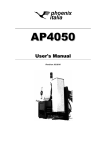
Burglar Alarm System
B2
1 2 3 4 5 6 7 8 9 10
12:30
Fri 03rd March
Partial
Armed
Disarmed
User’s manual
10_08 - 24848401
1
B2UC0002_Ute 24848401 10_08_GB.i1 1
7-10-2008 10:57:54
2
B2UC0002_Ute 24848401 10_08_GB.i2 2
7-10-2008 10:57:55
CONTENTS
Areas, Sceneries and Priority Levels
Page 4
Arming, Disarming and Partial Arming Page 6
Full Arming .................................................................................... 7
Device Test ................................................................................. 29
Input Test ...................................................................................... 29
Siren Test ....................................................................................... 29
Battery Test .................................................................................. 30
Partial Arming with the
“Arming through Sceneries” option active............. 8
Event Log .................................................................................... 31
Partial Arming with the
“Arming through Areas” option active ...................... 9
Forced Arming ........................................................................... 10
Control Panel Version ......................................................... 33
Disarming .................................................................................... 11
Areas and Users ......................................................................... 12
Alarm and Fault Management
Page 13
Alarm and Fault Signalling ................................................. 14
Alarm Display ............................................................................. 14
Siren off ......................................................................................... 15
Reset ................................................................................................ 16
Screen dimensions calibration .................................... 33
Choose Language ................................................................. 34
Auxiliary Keypad Functions
Page 35
Arming/Disarming ................................................................. 36
Partial Arming ............................................................................ 36
Resets Alarm Memory .......................................................... 37
Alarms Off .................................................................................... 37
Acoustic signals of the keypads .................................... 37
IR Receive and Key
Page 38
Arming/Disarming ................................................................. 39
“User Menu” Functions
Page 17
Partial Arming ............................................................................ 39
View Inputs State .................................................................. 18
Setting Menu ............................................................................ 19
Date and Time ........................................................................... 19
Users Management ............................................................... 20
General parameters ............................................................... 22
GSM Communicator Menu ............................................... 24
GSM Message Setting ........................................................... 24
Phone Book Setting ............................................................... 25
Extension Request .................................................................. 26
Automatic Program Disabling ........................................ 27
Change Keypad Code ........................................................ 28
Change IR Key Code ............................................................ 28
3
B2UC0002_Ute 24848401 10_08_GB.i3 3
7-10-2008 10:57:55
Areas, Sceneries and Priority Levels
AREAS
It is possible to divide the space to be protected into areas.
An Area of the system is nothing more than a logical grouping of sensors (the perimeter sensors of a building,
for example).
The subdivision of a system into areas is achieved simply by assigning one of the ten possible areas to each
input.
Subdividing the system into areas is essential if you plan to:
• Arm the system in partial mode as well
• Differentiate the access to particular environments according to the priority level assigned to the user (see
relevant section)
• Have differentiated signals for alarms coming from different zones.
To meet these needs, the system can be subdivided into a maximum of 10 areas.
SCENERIES
The term scenery is intended as a combination of areas that are activated according to set procedures.
During setting, the installer will create the sceneries containing groupings of areas which, upon activation, will
be placed in a state established by the installer himself.
A name can be assigned to the scenery which is suggestive of the functions associated with it (“Fence Sensors”,
for example).
A maximum of 10 sceneries can be set.
– For any changes regarding the assigning of the areas, sceneries or priority levels for the various
Users, contact your Installer.
– The Installer (in agreement with the User) must decide the partial activation mode of the system:
. Through free selection by the User of the areas to be activated
. Through activation of sceneries predefined by the Installer during setting.
4
B2UC0002_Ute 24848401 10_08_GB.i4 4
7-10-2008 10:57:55
PRIORITY LEVELS
In order to be able to carry out a particular operation, the user must always enter his “User Code” which, during
the setting procedures, has been assigned a priority level ranging from 1 to 4 and a variable number of the 10
available areas which he is permitted to manage. Each user can also be assigned a variable number of the 10
available sceneries which he is permitted to manage.
The priority level assigned to the “User Code” determines whether or not the user is permitted to perform certain
operations only on his assigned areas. Consult the tables below to learn what can and cannot be done with the
priority level assigned by the installer.
Action
Full or partial Arming/Disarming
of the sceneries or associated areas
Alarms Off (1)
Forced Arming (2)
Reset Alarm Memory
Access to the User Menu
Level 4
YES
Level 3
YES
Level 2
Arming only
YES
YES
YES
YES
YES
YES
YES
YES
NO
NO
NO
NO
A code set with priority level 1 does not cause any action, but only the valid typed data is memorized.
(1) The alarms are silenced by any operation (turning on or off, turning on partially, etc.) validly carried out by a User with Priority
Level 2, 3, 4, or through the appropriate control located on the main window in the presence of one or more alarms.
(2) The forced arming can be done with a code having Priority Level 3 or 4 using the dedicated command in the window that
displays the inputs already in alarm before the arming; the forced arming of one or more areas or the entire system entails
the temporary exclusion of the inputs already in a state of alarm before the arming.
Functions executable inside the User Menu and
accessible only to Users with Priority Level 3 and 4.
Action
Viewing the State and Temporary Exclusion of Inputs
Viewing the Event Log
Setting of date and time
Changing User Codes of others / Registering Keys of others
Changing own User Code / Registering own Key
Deletion of User Codes
Input Test
Siren Test
Battery Test
Level 4
YES
YES
YES
YES
Level 3
YES
YES
NO
NO
YES
YES
YES
YES
YES
YES
NO
YES
YES
YES
5
B2UC0002_Ute 24848401 10_08_GB.i5 5
7-10-2008 10:57:55
Arming, Disarming and Partial Arming
1 2 3 4 5 6 7 8 9 10
Pen for touchscreen
12:30
Fri 03rd March
Partial
Backlighting Button
With LED always lit.
Armed
Disarmed
Installer Menu Access
State of Areas Display
1 2 3 4 5 6 7 8 9 10
System Disarmed
1 2 3 4 5 6 7 8 9 10
System Completely Armed
1 2 3 4 5 6 7 8 9 10
System Partially Armed
1 2 3 4 5 6 7 8 9 10
Areas not ready (with System Disarmed)
Areas in alarm (with System Armed)
1 2 3 4 5 6 7 8 9 10
12:30
User Menu Access
Date and Time Display
Fri 03rd March
System Disarmed Indicator/Button
Partial
Armed
Disarmed
Not Ready
Indicator/Button for
System not ready for arming
System Armed Indicator/Button
System Partially Armed Indicator/Button
6
B2UC0002_Ute 24848401 10_08_GB.i6 6
7-10-2008 10:57:56
1 2 3 4 5 6 7 8 9 10
Armed
12:30
“Full” Arming
To arm the system, press the appropriate icon (fig.
1).
Fri 03rd March
Armed
Partial
Disarmed
Fig.1
Enter your User Code and press OK (fig. 2).
Enter Code
1
2
3
4
5
6
7
8
Esc 9
0
OK
At this point, the main window of the Control Panel
will display the active areas in the top part of the
screen and the state of the system in the bottom,
which will pass from Disarmed to Armed (fig. 3).
Fig.2
1 2 3 4 5 6 7 8 9 10
12:30
Fri 03rd March
Partial
Armed
- The areas will all be armed if the User that entered
the code has been granted permission, during the
setting procedures, to manage all the Areas.
Disarmed
Fig.3
7
B2UC0002_Ute 24848401 10_08_GB.i7 7
7-10-2008 10:57:56
1 2 3 4 5 6 7 8 9 10
Partial
12:30
With the “Arming through Sceneries” option active
Fri 03rd March
Armed
Partial
Partial Arming
In the event it is necessary to activate a predefined
combination of areas of the burglar alarm system,
press the indicated icon (fig. 4).
Disarmed
Fig.4
Select Scenery
Ext. protection
1
2
3
X
X
6
7
8
9
OK
10
ESC
Fig. 5
1 2 3 4 5 6 7 8 9 10
After having entered the User Code, the window
shown in figure 5 will appear in which, by pressing
on the arrows
, it is possible to select one of
the set sceneries.
The boxes underneath graphically represent the
state in which the areas will be set upon activation
of the scenery.
1
The area is armed.
2
The area is disarmed.
X
The area remains in its current state.
The main window (fig. 6) shows the arming state of
the areas and the partial arming icon is activated.
12:30
Fri 03rd March
Partial
Armed
Disarmed
Fig.6
8
B2UC0002_Ute 24848401 10_08_GB.i8 8
7-10-2008 10:57:56
1 2 3 4 5 6 7 8 9 10
Partial
12:30
Fri 03rd March
Armed
Partial
Partial Arming
With the “Arming through Areas” option active
In the event it is necessary to activate only some
areas of the burglar alarm system, press the indicated icon (fig. 7).
Disarmed
Fig. 7
Select Areas
1
2
3
4
5
6
7
8
Esc 9
0
OK
After having entered the User Code, another window will appear similar to that for entering the code
which, unlike the first, allows the user to select the
areas to be activated (fig. 8).
Once the areas have been selected, press OK.
Fig.8
1 2 3 4 5 6 7 8 9 10
12:30
Fri 03rd March
Partial
Armed
Disarmed
The main window (fig. 9) shows the arming state of
the areas and the partial arming icon is activated.
The partial activation of the system (for example)
may be useful in the case in which you would like
to move freely within the house by keeping all the
perimeter sensors active and excluding only the
volumetric sensors.
Fig.9
9
B2UC0002_Ute 24848401 10_08_GB.i9 9
7-10-2008 10:57:57
FORCED ARMING
1 2 3 4 5 6 7 8 9 10
12:30
Fri 03rd March
Partial
Armed
If, in the main window, one or more areas are flashing and the icon in the lower right corner changes
its state from “Disarmed” to “Not Ready”, this means
that one or more devices in the flashing areas are in
a state of alarm, and thus the system is not ready to
be armed (fig. 10).
If the arming button is pressed when the system is
“Not Ready”, a list will appear of the devices that are
in a state of alarm.
Disarmed
Fig.10
It is now possible to eliminate the causes that have
generated the alarm (by closing an open window,
for example) and proceed with the activation.
Not Ready Zones
In
Window kitchen
IR
SENS. kitchen
ESC
Alternatively, you can choose to arm the system
anyway, excluding one or more devices (open
windows or doors, for example). Pressing the button
(fig. 11) will force the arming of the system.
This operation will be displayed with the simultaneous lighting of the two icons representing full and
partial arming of the system (fig. 12).
The simultaneous lighting of the two icons can also
be caused by the temporary exclusion of inputs
by the User or their permanent exclusion by the
Installer.
Fig.11
1 2 3 4 5 6 7 8 9 10
12:30
Fri 03rd March
Partial
Armed
Disarmed
- The procedure described in this section is valid in
the case in which the “Automatic Arming” function
is not active. If, on the other hand, the “Automatic
Arming” function is active, the entire procedure
would be automated as described on page 23.
- Warning: the User who has been assigned the priority level 2 can only arm the system or the areas
assigned to him.
- Even though allowed by the control panel, it is
best not to use the forced arming in order to avoid
lowering the level of security guaranteed by the
system.
Fig.12
10
B2UC0002_Ute 24848401 10_08_GB.i10 10
7-10-2008 10:57:57
1 2 3 4 5 6 7 8 9 10
Disarming
12:30
Fri 03rd March
Armed
Partial
To disarm the fully or partially armed system, press
on the button “Disarmed” (fig. 13), enter your “User
Code” and press OK (fig. 14).
Disarmed
Fig.13
Enter Code
1
2
3
4
5
6
7
8
Esc 9
0
OK
Fig.14
1 2 3 4 5 6 7 8 9 10
12:30
Fri 03rd March
Partial
Armed
Disarmed
The system can be disarmed only by Users with
priority level 3 or 4; Users with priority level 2 can
only arm the system.
The priority level 2 can be assigned, for example, to
Users who must perform maintenance operations
or cleaning inside the building, so that once they
have completed their work they can only arm the
system.
Fig. 15
11
B2UC0002_Ute 24848401 10_08_GB.i11 11
7-10-2008 10:57:58
AREAS AND USERS
1 2 3 4 5 6 7 8 9 10
12:30
In addition to the system access privileges, during
setting, the installer can set some users so that they
can only arm and disarm certain areas.
Fri 03rd March
Armed
Partial
Disarmed
Fig. 16
If the User Code entered is only allowed access to
the areas from 6 to 10, then the arming of the system will be partial (fig. 17).
1 2 3 4 5 6 7 8 9 10
12:30
Fri 03rd March
Armed
Partial
Disarmed
Fig. 17
If the same user would like to partially arm the
system, however, he would not have access to all
the areas but would partially arm only the areas
assigned to him (fig. 18).
Select Areas
6
7
8
Esc 9
0
OK
Only the installer can change the access privileges
of the users and the areas assigned to them.
Fig. 18
12
B2UC0002_Ute 24848401 10_08_GB.i12 12
7-10-2008 10:57:58
Alarm and Fault Management
1 2 3 4 5 6 7 8 9 10
Burglar
Tamper
Alarm
PW Fault
Battery
Fault
Event Display
(by way of example, all the event icons are
displayed)
ELENCO
ALLARMI
Siren Off
Partial
Armed
Disarmed
Reset
Reset
Siren Off
The events described below are detected by the Control Panel regardless of the its state, with the exception of the “Burglar Alarm” which is detected only when the system/area is armed.
Burglar
Burglar Alarm
This event is triggered by the activation of the intrusion detectors (motion sensors, vibration
sensors, magnetic contacts, etc.).
Tamper
Tamper Alarm
This event is triggered by the activation of the anti-tampering devices present on modules,
sensors, containers, etc.
Alarm
Generic Alarm
This event is triggered by the activation of devices other than the intrusion detectors, such as
gas detectors, smoke detectors, emergency buttons, etc.
PW Fault
This event is triggered by the lack of mains power supply to the system.
PW Fault
Battery Fault
This event is triggered by the lack of power supply from the auxiliary batteries of the system.
Battery
Generic Fault
This event is triggered by faults on the devices in the system.
Fault
13
B2UC0002_Ute 24848401 10_08_GB.i13 13
7-10-2008 10:57:58
ALARM AND FAULT SIGNALLING
In case of an alarm or fault in progress, the main
window will change its usual appearance and,
in place of the date and time, a flashing icon will
appear which identifies the active event type; if
applicable, the area to which the device in alarm
has been associated will also be flashing (fig. 19).
1 2 3 4 5 6 7 8 9 10
Burglar
ELENCO
ALLARMI
Siren Off
Partial
Armed
Disarmed
Reset
Fig. 19
1 2 3 4 5 6 7 8 9 10
Burglar
Sabotaggio
Allarme
Guasto Rete Batteria
Guasto
ELENCO
ALLARMI
Siren Off
Partial
Armed
Disarmed
Reset
An alarm can also be “active” for an extremely short
time, (passing in front of an IR sensor, a window
being opened and then closed again, glass being
broken) after which the event is no longer “In
progress” but can be considered as “Occurred”. In
this case the icon representing the event is fixed
and the area concerned by the alarm will stop flashing (fig. 20).
The fact that the alarm has “Occurred” does not
exclude the possibility that the intrusion or tampering is still in progress, thus it is recommended that
utmost care be taken.
Fig. 20
Registered Events
Intrusione
Del
Sens. kitchen
01/ 03/ 2006
001
16:04
Del
ALARM DISPLAY
Pressing on the icon representing the event,
(whether in progress or occurred), you will access
the “Registered Events” window in which you can
view the events since the last activation.
No code must be entered in order to view this event
log. The event log allows you to verify the origin of
the alarm and the time at which it occurred without
necessarily changing the state of the system.
ESC
Fig. 21
14
B2UC0002_Ute 24848401 10_08_GB.i14 14
7-10-2008 10:57:59
SIREN OFF
Once the origin of the alarm has been checked and
it has been ascertained that there is no danger, the
sirens can be turned off by pressing the appropriate
button (fig. 22).
1 2 3 4 5 6 7 8 9 10
Burglar
Sabotaggio
Allarme
Guasto Rete Batteria
Guasto
ELENCO
ALLARMI
Siren Off
Armed
Partial
Disarmed
Reset
Fig. 22
Enter Code
1
2
3
4
5
6
7
8
Esc 9
0
OK
Similar to any other operation that changes the state
of the system, it will be necessary to enter the “User
Code” and press OK in order to immediately turn off
the sirens (fig. 23).
Fig. 23
15
B2UC0002_Ute 24848401 10_08_GB.i15 15
7-10-2008 10:57:59
RESET
The display, even after the sirens have been turned
off, will continue to show the icon of the activating
event until the temporary memory of the events is
reset (fig. 24).
1 2 3 4 5 6 7 8 9 10
Burglar
Sabotaggio
Allarme
Guasto Rete Batteria
Guasto
ELENCO
ALLARMI
Armed
Partial
Disarmed
Reset
Fig. 24
Enter Code
1
2
3
4
5
6
7
8
Esc 9
0
OK
By pressing the button “Reset” (fig. 24), entering
the “User Code” and pressing the button OK, the
temporary event log will be reset and the display
will return to the state it was in before the event
occurred (fig. 26).
Fig. 25
1 2 3 4 5 6 7 8 9 10
12:30
Fri 03rd March
Partial
Armed
Disarmed
Fig. 26
16
B2UC0002_Ute 24848401 10_08_GB.i16 16
7-10-2008 10:57:59
“User Menu” Functions
Press the button “User” (fig. 27), enter the “User
Code” and press OK (fig. 28).
1 2 3 4 5 6 7 8 9 10
The “User Menu” (fig. 29) contains a series of icons
which, when pressed, allow access to the User
functions, which are:
12:30
Fri 03rd March
View Inputs State
Armed
Partial
Access to the setting functions*
Disarmed
1 2 3
4 5 6
7 8 9
0
Fig. 27
Change Keypad Code
Change IR Key Code
Enter Code
1
2
3
4
5
6
7
8
Esc 9
0
OK
TEST
Device Test
Event Log
Screen dimensions calibration
Display of the Firmware ID and version of
the Control Panel
Fig. 28
Choose Language
Buzzer off
User Menu
P P P
S S S
S
P
S S S
Visualizza
P P P
Setting
1 2 3
4 5 6
7 8 9
0
Buzzer on
MEM ORY
TEST
ESC
- Access to the “User Menu” is reserved for Users
with Priority Level 3 or 4.
* Access to the “Setting” section of the “User Menu”
is reserved for Users with Priority Level 4.
Fig. 29
17
B2UC0002_Ute 24848401 10_08_GB.i17 17
7-10-2008 10:58:00
S S S
S
View Inputs State
In
In
In
In
IR
IR
S S S
View
Window bath
Win. bedroom1
Win. bedroom2
Door kitchen
Sen. draw.-room
Sen. kitchen
OK
ESC
View Inputs State
From this window it is possible to check the current
state of all the system inputs (fig. 30).
This function is very useful in the event the main
window of the system is in the “Not Ready” state
(fig. 10), in order to view the effective state of the
inputs before proceeding with the full or partial
arming of the system.
Fig. 30
The icons in the first column next to the device
name (fig. 31) indicate whether or not the device is
included.
The user can exclude a device by pressing on the
icon, but the change is valid only for one activation cycle of the system (Temporary Exclusion). The
permanent exclusion of a device can only be set by
an installer.
View Inputs State
In
In
In
In
IR
IR
Window bath
Win. bedroom1
Win. bedroom2
Door kitchen
Sen. draw.-room
Sen. kitchen
OK
Device Excluded
ESC
Device Included
Fig. 31
The next column (fig. 32) graphically displays the
current state of the devices.
View Inputs State
In
In
In
In
IR
IR
Window bath
Win. bedroom1
Win. bedroom2
Door kitchen
Sen. draw.-room
Sen. kitchen
OK
Device Fault
Tamper in progress
Device in alarm
ESC
Press OK to confirm the selections made before
exiting from the screen with ESC and returning to
the “User Menu”.
Fig. 32
18
B2UC0002_Ute 24848401 10_08_GB.i18 18
7-10-2008 10:58:00
Setting Menu
Setting Menu
0 123456789
0 123456789
0 123456789
0 123456789
1 2
From the “User Menu” (fig. 29), pressing the “Setting”
icon accesses the “Setting Menu” in which it is possible to set a series of functions described below.
Gen. Param.
ESC
- Access to the “Setting Menu” is reserved for
Users with Priority Level 4.
Fig. 33
Date & Time Setting
Hours
18
1 2
55
From the “Setting Menu” (fig. 33), pressing the
appropriate icon will access the window for setting
the Date and Time.
Set the correct time by selecting the area to be
modified (fig. 34) and using the arrows on the side.
ESC
OK
Fig. 34
Gio
17
Month-Year Gen
08
OK
Press OK to confirm the selections made, and then
press on the arrow at the bottom of the window to
access the next screen.
Set the correct day, month and year by selecting
the area to be modified (fig. 35) and using the
arrows on the side.
Date & Time Setting
Date
DATE AND TIME
Press OK to confirm the selections made before
exiting from the screen with ESC.
ESC
Fig. 35
19
B2UC0002_Ute 24848401 10_08_GB.i19 19
7-10-2008 10:58:01
Users Management
USERS MANAGEMENT
Users 01
4
2
3
1
1
2
3
4
5
6
7
8
9
10
1
2
3
4
5
6
7
8
9
10
1
2
3
4
Keypad Code
IR Key Code
OK
ESC
DEL
From the “Setting Menu” (fig. 33), pressing the
appropriate icon will access the window “Users
Management”. Access to this section is reserved
for Users who, during the setting phase, have been
assigned the Priority Level 4. They can manage all
the Users, assign each User a name and associate
to this name a key and a code to enter on the
keypads.
Fig. 36
Pressing the icons
on the first line (fig. 36) will
scroll through the list of users available. Pressing on
the User selected, it is possible to assign the User a
name using the alphanumeric keypad (fig. 37).
Press OK to confirm the selections made before
exiting from the window with ESC.
Enter User Name
Marco
A
B
C
D
E
F
G
H
I
J
K
L
M
N
O
P
Q
R
S
T
U
V W X
Y
Z
'
.
-
0
1
4
5
6
7
8
2
CAP
3
DEL BkSp
OK
9
ESC
Fig. 37
Users Management
Marco
1
3
4
2
3
1
1
2
3
4
5
6
7
8
9
10
1
2
3
4
5
6
7
8
9
10
1
2
3
4
2
Keypad Code
IR Key Code
OK
DEL
ESC
The line of the display indicated by number 1 (fig.
38) represents the areas of the system that the user
can manage.
The line of the display indicated by number 2
represents the possible sceneries (if set) that the
user can activate.
The line of the display indicated by number 3 indicates the priority level assigned to the User.
This data cannot be changed by the User since it
was established during the setting phase by the
Installer, the only holder of the “Installer Code”
which is required in order to change these settings.
Fig. 38
20
B2UC0002_Ute 24848401 10_08_GB.i20 20
7-10-2008 10:58:01
Now, pressing with the pen provided near the line
indicated by number 4 “Keypad Code” (fig. 39) will
access the window “Keypad Code Registration”
(fig. 40).
Users Management
Marco
4
2
3
1
1
2
3
4
5
6
7
8
9
10
1
2
3
4
5
6
7
8
9
10
1
2
3
4
Keypad Code
4
IR Key Code
OK
5
DEL
ESC
Fig. 39
Keypad Code Registration
Marco
Enter User Code
0 1 2 3 4
5 6 7 8 9
012345
Valid Code
OK
By entering a code with 4 to 6 digits, this code will
be associated with the User indicated on the first
line of the display (fig. 40).
More than a million combinations are available.
Press OK to confirm before returning to the previous window with ESC.
ESC
Fig. 40
IR Key Code Registration
Marco
Press IR Key Button
near
a IR Key Receiver
Now, pressing with the pen provided near the line
indicated by number 5 “Key Code” (fig. 39) and following the instructions on the display, it is possible
to associate a key code with the User (fig. 41).
Press OK to confirm before returning to the previous window with ESC.
IR Key Registered
OK
ESC
Fig. 41
21
B2UC0002_Ute 24848401 10_08_GB.i21 21
7-10-2008 10:58:02
The Users who, during the setting phase, have been
assigned the Priority Level 4 can also remove a User
and the associated codes from the list using the key
DEL (fig. 42).
Users Management
Marco
4
2
3
1
1
2
3
4
1
2
3
4
5
6
7
8
9
10
Keypad Code
IR Key Code
OK
DEL
ESC
Fig. 42
Users Management
Start
devices codes?
OK
ESC
Press OK (fig. 43) to confirm the selections made
before exiting from the screen with ESC.
Fig. 43
General Parameters
GENERAL PARAMETERS
PW restore State
Previous
From the “Setting Menu” (fig. 33), pressing the
appropriate icon will access the window for viewing the general parameters set by the Installer and
setting some general parameters that can be set
by the User.
Supervision
YES
GSM Control
NO
Arming through Sceneries
Aut. Arming
YES
OK
ESC
Fig. 44
22
B2UC0002_Ute 24848401 10_08_GB.i22 22
7-10-2008 10:58:02
PW restore State (cannot be changed by the User)
On
In the event both the battery and mains power supply fails for the control panel, the control panel will be
automatically set in the armed state when the power supply voltage is restored.
Off
In the event both the battery and mains power supply fails for the control panel, the control panel will be
automatically set in the disarmed state when the power supply voltage is restored.
Previous
In the event both the battery and mains power supply fails for the control panel, the control panel will be
automatically set in the previous state when the power supply voltage is restored.
Supervision (cannot be changed by the User)
This parameter allows to select whether or not the system can be managed by external supervision systems.
GSM Control (can be changed by the User)
This parameter allows to select whether or not the system can be remotely managed by means of a GSM
dialler (BXGM0001).
Arming through Areas / Arming through Sceneries (cannot be changed by the User)
This parameter allows to select if the partial activation of the system can occur through the activation of
areas chosen one at a time by the User (Arming through Areas) or through the activation of predefined
sceneries containing activation commands for groups of areas (Arming through Sceneries).
Automatic Arming (can be changed by the User)
When the function is active, if one or more inputs are in alarm during the arming of the system, these
will be temporarily excluded automatically and will return to being included only after the subsequent
disarming of the system.
When the function is not active, if there are any inputs in a state of alarm, the control panel will interrupt
the arming of the system and wait for the causes of the alarm to be eliminated (closing an open window,
for example). In any case, a User with priority level 3 or 4 can “force” the arming following the procedures
described in the section “Forced Arming” of the B2UC0002 User Manual.
Press OK to confirm the selections made before exiting from the screen with ESC and returning to the “Setting
Menu”.
23
B2UC0002_Ute 24848401 10_08_GB.i23 23
7-10-2008 10:58:02
GSM Communicator Menu
a
e
b
f
g
h
c
d
GSM COMMUNICATOR MENU
From the “Setting Menu” (fig. 33), pressing on the
appropriate icon accesses the “GSM Communicator
Menu” (fig. 45) in which it is possible to set some
parameters regarding the message sending procedures and create a phone book.
Phone Book
Messages
ESC
Fig. 45
GSM Message Setting
Messages
Burglar Alarm
1
2
3
4
5
6
7
8
9 10
Vocal Messages YES
SMS
No
Personal Message = –
OK
Fig. 46
These changes can only be made by Users who,
during the setting phase, have been assigned the
Priority Level 4.
ESC
GSM Message Setting
From the “GSM Communicator Menu” (fig. 45),
select the “Messages” icon to access the “GSM Message Setting” window (fig. 46).
Pressing the icons
next to the first item in the
window (fig. 46), it is possible to scroll through the list
of events that generate a signal.
For each event you can select which numbers, from
the 10 possible numbers in the phone book, should
receive the warning message when the selected
event occurs.
Using the icons
located on the next two
lines, you can select the format in which the messages should be sent.
Press OK to confirm the selections made before
returning to the previous window with ESC.
The “Personal Message” function is not active.
24
B2UC0002_Ute 24848401 10_08_GB.i24 24
7-10-2008 10:58:03
Phone Book Setting
Tel. Number =
Phone Book Setting
01
From the “GSM Communicator Menu” (fig. 45),
select the “Phone Book” icon to access the “Phone
Book Setting” window (fig. 47).
Massimiliano
+3904225858585
032
SMS di conferma
No
ESC
OK
The second line allows you to select which User and
relative phone number is to be associated with the
selected position.
At this point, press on the first icon
to call up
the keypad with which to enter the phone number
(fig. 48).
If the phone number has more than 14 digits, you
will have to enter the extra digits after pressing on
.
the second icon
Fig. 47
Enter Phone Number
+393478
A
B
C
D
E
F
G
H
I
J
K
L
M
N
O
P
Q
R
S
T
U
V W X
Y
Z
+
.
-
0
1
4
5
6
7
8
CAP
2
OK
3
DEL BkSp
Fig. 48
On the first line, you can select the position (1
through 10) in which to store the User’s number in
the phone book.
9
ESC
The telephone commands sent to the control
panel will be carried out only if the number from
which they are sent is present in the phone book.
Furthermore, the User associated with the number
must enter his “User Code” and be assigned a
“Level of priority” that allows him to carry out the
requested action.
NOTE. For further information, see the instructions of the BXGM0001.
The last line in the “Phone Book Setting” window
(fig. 47) allows you to select if the phone book
number should receive SMS messages or not.
Press OK to confirm the selections made before
returning to the previous window with ESC.
Press ESC also on the window shown in figure 45 in
order to return to the “Setting Menu”.
The numbers MUST be preceded by the proper
international prefix (+39 for Italy).
25
B2UC0002_Ute 24848401 10_08_GB.i25 25
7-10-2008 10:58:03
Extension Request
Extension
EXTENSION REQUEST
15
From the “Setting Menu” (fig. 33), pressing the
appropriate icon will access the window “Extension
Request” (fig. 49).
OK
Fig. 49
ESC
The extension request can be used when there is
a need to suspend execution of all the automatic
actions controlled by the timer.
Pressing the icons
, the extension time can
be changed from 15 to 90 minutes with “steps” of
15 minutes.
Pressing the button OK, the timer suspension will
immediately begin for the set period of time, after
which all the suspended actions will be executed.
Before the extension time has expired, another
request can be made for up to a maximum number
of 5 times.
If you ask for another extension before the previous
one has finished, any remaining time will NOT be
added to the new extension period but instead
be lost. This means you will only be able to use
one entire extension period after each additional
request.
Therefore it is advisable to renew the extension
request near the end of the previous time so as to
make better use of this function.
The “Extension Request” can be performed only
by Users who, during the setting phase, have been
assigned the Priority Level 4.
26
B2UC0002_Ute 24848401 10_08_GB.i26 26
7-10-2008 10:58:03
Automatic Program Disabling
Timer
AUTOMATIC PROGRAM DISABLING
Off
From the “Setting Menu” (fig. 33), pressing the
appropriate icon will access the window “Automatic
Program Disabling” (fig. 50).
With the Timer Off (default setting), all the timer
settings are blocked.
OK
ESC
With the Timer On, the timer settings are executed.
Fig. 50
The actions which have not been executed during
the blocked period (Timer Off) will NOT be executed when the normal Timer operation is restored
(Timer On).
The “Automatic Program Disabling” can be performed only by Users who, during the setting phase,
have been assigned the Priority Level 4.
27
B2UC0002_Ute 24848401 10_08_GB.i27 27
7-10-2008 10:58:04
1 2 3
4 5 6
7 8 9
0
Change Keypad Code
Luca
Enter User Code
0 1 2 3 4
5 6 7 8 9
012345
Valid Code
OK
ESC
Fig. 51
Change Keypad Code
From the “User Menu” (fig. 29), by pressing the
appropriate button we will access the “Change
Keypad Code” window (fig. 51).
On the first line will appear the name of the User
associated with the “User Code” that we have
entered for access to the “User Menu”.
Once the new number has been entered, press OK
to confirm the selection before returning to the
previous window with ESC.
The B2 Control Panel is able to manage up to 63
Users, the “User Code” 64 is associated with a special
function that allows you to request help without
arousing the suspicion of a possible assailant. By
entering the code associated with User 64, it will
actually be possible to deactivate the control panel
and at the same time activate the “Silent Alarm” (if
set by the Installer).
Change IR Key Code
Change IR Key Code
Luca
Press IR Key Button
near
a IR Key Receiver
IR Key Registered
OK
Fig. 52
ESC
From the “User Menu” (fig. 29), by pressing the
appropriate button we will access the “Change IR
Key Code” window (fig. 52).
On the first line will appear the name of the User
associated with the “User Code” that we have
entered for access to the “User Menu”.
Following the instructions on the screen, a new key
code can be assigned to the User.
Press OK to confirm the selection before returning
to the previous window with ESC.
28
B2UC0002_Ute 24848401 10_08_GB.i28 28
7-10-2008 10:58:04
Test Menu
TEST
Device Test
In In
12V
In In
12V
From the “User Menu” (fig. 29), pressing the icon
TEST will take us to the “Test Menu” (fig. 53) that
allows us to test the correct operation of the inputs,
sirens and batteries in the system.
ESC
Fig. 53
In In
Input Test
In
4 IN MOD 01.1
In
4 IN MOD 01.2
In
4 IN MOD 01.4
WALL IR SENSOR 01
IR
IR
12V
In In
12V
INPUT TEST
Only the inputs that are in a state of alarm will
appear in this window (fig. 54).
Thus, by materially activating the inputs, we can
check their correct operation, name and location.
WALL IR SENSOR 02
ESC
Fig. 54
Siren Test
EXT. SIREN 01
EXT. SIREN 02
On
Off
SIREN TEST
The legend “ON” or “OFF” next to the name of the
device acts as a switch (fig. 55).
By simply pressing on the legend we can turn the
sirens on or off.
ESC
Fig. 55
29
B2UC0002_Ute 24848401 10_08_GB.i29 29
7-10-2008 10:58:04
Battery Test
A
BATTERY TEST
PW.
01
EXT. SIREN 02
By simply pressing on the name of the device, we
will be informed about the state of the battery
housed inside the device (figg. 56, 57).
ESC
Fig. 56
Battery Test
Battery CHARGED
ESC
Fig. 57
30
B2UC0002_Ute 24848401 10_08_GB.i30 30
7-10-2008 10:58:05
MEM ORY
Event Log
Burglar
Mod 4 IN 03.4
15/ 03/ 2006
001
11:04
EXT Siren 01
14/ 03/ 2006
Door 03
12/ 03/ 2006
002
08:09
003
06:20
Event Log
From the “User Menu” (fig. 29), by pressing the icon
we will access the “Event Log” window.
MEM ORY
Tamper
Alarm
Del
ESC
Del
The “Event Log” (fig. 58) is structured so as to provide
a precise picture of the events concerning the system, whether these are caused by burglar attempts,
tampering, alarms and faults or simply due to a User
arming or disarming the system.
Fig. 58
Pressing the icons
, we can scroll through
the events and check their progression, indicated
by the number next to the name of the device that
generated the event. At the end of the list, the scrolling will start again from the beginning.
Event Log
Fault
Fault
Del
Bus PW
15/ 03/ 2006
001
16:04
Bus PW
15/ 03/ 2006
002
11:09
Del
Fig. 59
ESC
In the case of burglar, tamper or alarm events, for
example (fig. 58), next to the icon showing the
event, we can read the name of the input that generated the event and the date and time in which it
was activated.
If the event is different from burglar, tamper or generic alarms, it will be divided into two parts (fig. 59).
The first part (with the icon in negative) reports the
date and time of the end of the event; the second
part (with the icon in positive) reports the date and
time of the start of the event.
The progressive numbering next to the name of the
device that generated the event indicates the most
recent event with the number 001.
31
B2UC0002_Ute 24848401 10_08_GB.i31 31
7-10-2008 10:58:05
Each User has his own code and an access key to
which it is possible to associate the name of the User.
Event Log
1 2 3
4 5 6
7 8 9
0
Mario
16/ 03/ 2006
001
08:04
1 2 3
4 5 6
7 8 9
0
Mario
15/ 04/ 2006
002
11:09
For this reason, in the “Event Log”, it is possible to
find indication of the arming or disarming of the
system (by keypad or key) associated with the name
of the User (fig. 60).
Adele
14/ 04/ 2006
002
10:09
In this case as well, the event will be divided into
two parts.
Del
Del
Fig. 60
ESC
The first part (with the icon in negative) reports the
date and time of the disarming of the system; the
second part (with the icon in positive) reports the
date and time of the arming of the system.
The “Event Log” can be cancelled only by an installer
with the “Installer Code”
32
B2UC0002_Ute 24848401 10_08_GB.i32 32
7-10-2008 10:58:05
User Menu
P P P
S S S
S
P
S S S
P P P
Visualizza
Setting
Screen dimensions calibration
1 2 3
4 5 6
7 8 9
0
MEM ORY
TEST
ESC
From the “User Menu” (fig. 61), by pressing the
appropriate icon and following the simple instructions (fig. 62), we can correctly calibrate the screen
dimensions.
For a correct calibration of the screen dimensions,
position the appropriate pen in the farthest point
of the corner indicated by the arrow.
Fig. 61
It is recommended that you strictly follow the
video calibration instructions in order to avoid
malfunctioning of the terminal
Touch
with the pen
the bottom right corner
of the screen
for 3 seconds minimum
Fig. 62
Control Panel Version
Control Panel Version
ID: 16777215
Ver.: 55.55
From the “User Menu” (fig. 61), pressing the button
“B2” will display the Firmware ID and version of
the control panel (fig. 63); this information may be
particularly useful in case you need to contact a
service technician.
ESC
Fig. 63
33
B2UC0002_Ute 24848401 10_08_GB.i33 33
7-10-2008 10:58:06
Choose Language
DEU
ENG
ESP
FRA
Choose Language
ITA
From the “User Menu” (fig. 61), pressing the appropriate icon allows the user to select the system
language.
POR
ESC
The “Choose Language” window will appear
automatically when the system is turned on or
turned back on after a complete power outage.
Fig. 64
34
B2UC0002_Ute 24848401 10_08_GB.i34 34
7-10-2008 10:58:06
Auxiliary Keypad BXTAIN01 Functions
Green “Mains PW On” LED
1
2
3
Green “System Armed/Disarmed” LED
4
5
6
Red “Alarm” LED
7
8
9
0
Yellow “Partial Arming” LED
LED
Colour
mains
Meaning
Icon
on
flashing
off
green
mains power supply on
battery fault
mains power
outage
on/off
green
armed
exit delay
disarmed
alarm
red
Alarm (system armed) /
Not Ready (system disarmed)
alarm memory
No alarm /
Ready
partial
yellow
System partially armed or
inputs temporarily excluded
–
–
KEYPAD STATES
1
2
3
1
2
3
4
5
6
4
5
6
7
8
9
7
8
9
0
”Soft” backlighting
Keypad in Stand-by
0
”Intense” backlighting
Keypad in use
35
B2UC0002_Ute 24848401 10_08_GB.i35 35
7-10-2008 10:58:06
1
2
3
4
5
6
7
8
9
The auxiliary keypad BXTAIN01 allows the user to
manage some basic functions of the burglar alarm
system through the key combinations illustrated in
the table below.
0
Key Combination
< User Code> +
Action
O
< User Code> +
O
< User Code> +
O
< User Code> +
O
Arming / Disarming of the control panel
Starts the Partial Arming procedure
Resets the Alarm Memory
Turns off the Alarms
+
1
Deactivates the keypad Buzzer
+
2
Deactivates the key backlighting
+
3
Deactivates the state LEDs
1
2
3
4
5
6
7
8
9
0
Zone of the keypad used for selecting the areas.
ARMING/DISARMING
To arm or disarm the system, press <User Code> +
; the LEDs of the numerical keys 1-10 display
the arming state of the areas, while the LEDs of the
other keys and the state LEDs remain in the state of
“intense” backlighting.
The areas not assigned to the User will in any case
remain off, and their state cannot be changed.
PARTIAL ARMING
If the User begins the partial arming procedure
by entering <User Code> +
, the LEDs of the
numerical keys 1-10 will display the current arming
state of the areas, while the LEDs of the other keys
will remain in the state of “intense” backlighting and
the state LEDs will flash.
36
B2UC0002_Ute 24848401 10_08_GB.i36 36
7-10-2008 10:58:07
The areas not assigned to the User will in any case
remain off, and their state cannot be changed.
If the ‘partial arming through areas’ mode has been
set, the user can only change the state of the areas
assigned to him; by selecting these areas, their state
will alternate between armed and disarmed.
N.B.: When selecting the areas, wait until the visual indication on the keypad is effective before
pressing the next key.
When finished, just press
to partially arm the
system in the selected manner. If you would like to
quit the procedure without changing the system
.
state, press the button
If no key is pressed within 15 seconds, the procedure will be quit automatically.
If instead the ‘partial arming through sceneries’
mode has been set, the user can only choose a
scenery to be activated from among those assigned
to him by the installer. The arming of the scenery is
carried out by pressing the key corresponding to
the scenery to be activated.
Provided that the number is correct and the selected scenery is correctly assigned to the User, the
procedure will terminate successfully. Otherwise,
the procedure will be quit without making any
changes to the system.
If no key is pressed within 15 seconds, the procedure will be quit automatically.
RESET ALARM MEMORY
To cancel the alarm memory regarding the single
activation cycle, enter <User Code> + .
All the alarms concerning the system, other than the
“Silent Alarm”, trigger the continuous sounding of
the keypad buzzer.
Furthermore, the keypads can be set during installation so as to emit a sound to advise the user of
the imminent activation of the alarm system; this
function is necessary in the event the keypad is positioned inside the protected area and accessing the
same keypad entails the activation of some sensor.
The time necessary to enter the protected zone and
enter the User Code on the keypad is known as the
“Entry Delay”; the passing of this time is marked
by the continuous sounding of the buzzer inside
the keypad.
The time necessary to enter the code on the keypad
and exit the protected zone is known as the “Exit
Delay”.
The passing of the “Entry Delay” and “Exit Delay”
time is marked by the continuous sounding of the
buzzer inside the keypad.
If the user tries to arm the system with devices in
alarm (red LED lit), the buzzer will sound intermittently to advise that the system cannot be armed.
The keypad buzzer will in any case be active during
the alarm time.
If you are in the “Installer Menu”, this is signalled on
the “mechanical” keypads and receivers by all four
LEDs flashing intermittently.
ALARMS OFF
To turn off the active alarm signals, enter <User
.
Code> +
ACOUSTIC SIGNALS OF THE KEYBOARDS
Any fault concerning the system triggers the intermittent sounding of the keypad buzzer.
The sounding of the buzzer, however, can be disabled with a setting option for each individual
keypad.
37
B2UC0002_Ute 24848401 10_08_GB.i37 37
7-10-2008 10:58:07
BXINIR receiver and BXKEIR01 infrared key
Green “Mains PW On” LED
Green “System Armed/Disarmed” LED
Red “Alarm” LED
Yellow “Partial Arming” LED
Meaning
LED
Colour
mains
green
on/off
green
armed
exit delay
disarmed
alarm
red
Alarm (system armed) /
Not Ready (system disarmed)
alarm memory
No alarm /
Ready
partial
yellow
System partially armed
or inputs temporarily excluded
–
–
on
flashing
off
mains power supply on
battery fault
mains power
outage
Functions control button
”Transmission in progress” LED
38
B2UC0002_Ute 24848401 10_08_GB.i38 38
7-10-2008 10:58:08
ARMING/DISARMING
To Arm or Disarm the control panel using the infrared key, just bring the key within two metres of the
receiver and press the button located on the key
itself for at least 0.5 seconds and not more than 3
seconds.
Inside the transparent shell of the infrared key
there is an LED, activated by pressing the button,
which acts as an indicator of the successful transmission; the successful reception of the signal
by the receiver is indicated by the simultaneous
lighting of all the LEDs.
PARTIAL ARMING
To start the procedure using the infrared key, just
aim it at the receiver, at a distance of at least one
metre, and press the button located on the key itself
for a maximum time of 3 seconds.
The beginning of this procedure will be signalled by
a series of simultaneous flashes, quick and dim, of
the four state LEDs. From this moment on, up until
the User exits the partial arming procedure, the fixed
and intense lighting of the LEDs represents the arming of the first four areas assigned to the User.
By pressing the button on the key to produce infrared pulses with a duration of at least 0.5 seconds but
less than 3 seconds, the 4 LEDs of the receiver will
display, in succession, the sixteen possible combinations for arming the four areas.
N.B.: Wait until the pressing of the key on the
remote control produces the lighting of the LED
before pressing the same key again.
To terminate the procedure, an infrared pulse with a
duration of more than 3 seconds must be sent.
At the end of the procedure, the meaning of the
LEDs will return to normal.
If you are in the “Installer Menu”, this is signalled on
the “mechanical” keypads and receivers by all four
LEDs flashing intermittently.
39
B2UC0002_Ute 24848401 10_08_GB.i39 39
7-10-2008 10:58:08
BRAHMS ELETTRONICA S.r.l.
Via Gran Sasso, 18
20010 Bareggio/MILANO/Italy
http: www.brahmselettronica.it
e-mail: [email protected]
40
B2UC0002_Ute 24848401 10_08_GB.i40 40
7-10-2008 10:58:08