1
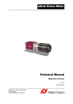
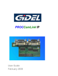
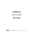
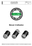
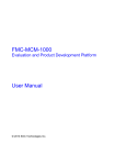
Sigmaringer Str. 121 70567 Stuttgart Tel.: +49 711 997 996 3 www.maxxvision.com User Manual USB2.0 FA Camera Series www.crevis.co.kr REVISION HISTORY Rev 0.8 Page : 2/35 User Manual USB2.0 FA Camera Series www.crevis.co.kr Rev. Model Data Description Page 0.1 ALL 2008-09-17 Established 0.2 ALL 2008-10-09 revised Table 6 added 1.4 Mechanical drawings of Overlap 8 11 function 0.3 0.4 ALL ALL 2008-10-23 2009-06-30 revised Demo Program 9 added Troubleshooting 26 added specification of color and board models 6~9 changed pictures of control panel. 17~23 added functions of board models. 22, 32 0.5 ALL 2009-07-16 Revised 22dB into 24dB. 0.6 ALL 2009-08-27 Added notices 0.7 ALL 2009-08-31 Modified specifications 0.8 ALL 2009-11-16 Added PC Spec. 20 6 6~9 Added the functions of sharpness 26 Added the function of BinningHorizontal 18 0.9 ALL 2010-02-09 Added the function of InterpolationModel 20 1.0 Color 2010-08-17 added Troubleshooting 34 1.1 Board type 2011-02-11 changed pictures of board type camera. 12 The features and specifications, and other information provided in this preliminary data sheet, are subject to change without notice. Crevis co., Ltd. Reserves the right to make design changes without prior warning. Rev 0.8 Page : 3/35 User Manual USB2.0 FA Camera Series www.crevis.co.kr Contents 1. General.....................................................................................................................................................4 1.1 Components......................................................................................................................................4 1.2 System Requirements......................................................................................................................5 1.3 Specifications...................................................................................................................................6 1.4 Dimension (mm).............................................................................................................................11 2 . Demo Program.......................................................................................................................................13 2.1 McamU Demo................................................................................................................................13 2.1.1 Start.....................................................................................................................................14 2.1.2 Demo menus........................................................................................................................15 2.1.3 Status bar.............................................................................................................................16 2.2 Control Panel.................................................................................................................................17 2.2.1 Camera Info ........................................................................................................................17 2.2.2 Image Info ...........................................................................................................................18 2.2.3 Trigger Ctrls........................................................................................................................19 2.2.4 Analog Ctrls.........................................................................................................................20 2.2.5 Strobe Ctrls.........................................................................................................................21 2.2.6 I/O Ctrls...............................................................................................................................22 2.2.7 Gamma Ctrls........................................................................................................................23 2.2.8 User Set...............................................................................................................................24 2.3 Processing......................................................................................................................................25 2.3.1 Sharpening ..........................................................................................................................25 3. Functions.................................................................................................................................................26 3.1 Normal mode .................................................................................................................................26 3.2 Trigger mode.................................................................................................................................26 3.2.1 Trigger rising edge.............................................................................................................28 3.2.2 Trigger falling edge............................................................................................................28 3.2.3 Trigger Level High..............................................................................................................29 3.2.4 Trigger Level Low..............................................................................................................29 3.2.5 Overlap mode.......................................................................................................................30 3.3 Strobe mode...................................................................................................................................31 3.3 GPIO Function................................................................................................................................33 4. Troubleshooting......................................................................................................................................34 Rev 0.8 Page : 4/35 1. General 1.1 Components Fig 2: Instruction Manual Fig 1: Install CD Fig 3: USB Cable Fig 4: DC-iris cable No. Accessory Quantity ① Instruction Manual 1EA ② Install CD 1EA ③ USB dedicated Cable 1EA Option ④ Auto DC-Iris Cable 1EA Option(Only board type) Rev 0.8 Reference Page : 5/35 1.2 System Requirements PC with at least one USB2.0-interface PC with CPU Clock Monochrome Models : at least 1.6GHz Color Models : at least 3.0GHz OS : Win2000, WinXP, Win Vista 32-Bit The USB 2.0 Port must support a 500mA. USB2.0 certified cables should be used. ☞ Notice - USB 2.0 PCMCIA Card may not work with - This camera do not support USB1.1 USB 2.0 1.3 Specifications The model name is given according to below table. Rev 0.8 Page : 6/35 1) Products specifications - Monochrome Models(Box Type) Item MV-BS20U MV-BX30U MV-BV30U / BV20U Resolutions 1280 X 1024 1024 X 768 640 X 480 Pixel size 4.65㎛ X 4.65㎛ 4.65㎛ X 4.65㎛ 7.4㎛ x7.4㎛ / 9.9㎛ x9.9㎛ Optical senor class 1/2” 1/3” 1/3” / 1/2” Pixel Clock Frame Rates 28.6363MHz 15fps 30fps Binning HRS 70fps X2 1/2, 1/4, 1/6 1/2, 1/3, 1/4 1/2, 1/3, 1/4 Exposure Trigger Random Trigger Pulse width/Fixed Shutter Trigger Level Low Level : 0 ~2V, High Level: 5 ~ 24V (Isolation Voltage 50V) Gain 0dB ~ 24dB Shutter 125us ~ 66.9ms Gamma 88.9us ~ 35.2ms 54.6us ~ 14.3ms Off(1), 0.45, 0.7, Table(Adjustable) SNR 58dB 58dB 60dB Min, Illumination 1.0lx(F1.4) 2.0lx(F1.4) 1.0lx(F1.4) Video Output Mono 8bit, 10bit Optical Axis Accuracy Pixel Center ±0.1mm Vibration(20~200Hz) Sweep interval : 300sec 10G Test Time: 10min(XYZ Dir) Power USB Bus power(DC5V) , <2.5W Dimension 29mm X 29mm X 29mm(Without mount) Operating temperature Performance Guaranteed : 0℃ ~ +40℃ (Operation Guaranteed : -5℃ ~ +45℃ ) Operating Humidity 20 ~ 80%RH Weight Approx. 44g USB Driver Win2000, WinXP, Win Vista(x86), Win 7(x86) USB Viewer/SDK Win2000, WinXP, Win Vista x86, Win 7-x86, C/C++ CE EN61326-1 Class A RoHS RoHS Compliant Rev 0.8 Page : 7/35 - Color Models(Box Type) Item MV-CS20U MV-CX30U MV-CV30U Resolutions 1280 X 1024 1024 X 768 640 X 480 Pixel size 4.65㎛ X 4.65㎛ 4.65㎛ X 4.65㎛ 7.4㎛ x7.4㎛ Optical senor class 1/2” 1/3” 1/3” Pixel Clock Frame Rates 28.6363MHz 15fps 30fps Binning HRS 70fps Not supported 1/2, 1/4, 1/6 1/2, 1/3, 1/4 1/2, 1/3, 1/4 Exposure Trigger Random Trigger Pulse width/Fixed Shutter Trigger Level Low Level : 0 ~2V, High Level: 5 ~ 24V (Isolation Voltage 50V) Gain 0dB ~ 24dB Shutter 125us ~ 66.9ms Gamma 88.9us ~ 35.2ms 54.6us ~ 14.3ms Off(1), 0.45, 0.7, Table(Adjustable) SNR 58dB 58dB 60dB Min, Illumination 2.0lx(F1.4) 3.0lx(F1.4) 2.0lx(F1.4) Video Output Mono8, BayerBG8, RGB8Packed Optical Axis Accuracy Pixel Center ±0.1mm Vibration(20~200Hz) Sweep interval : 300sec 10G Test Time: 10min(XYZ Dir) Power USB Bus power(DC5V) , <2.5W Dimension 29mm X 29mm X 29mm(Without mount) Operating temperature Performance Guaranteed : 0℃ ~ +40℃ (Operation Guaranteed : -5℃ ~ +45℃ ) Operating Humidity 20 ~ 80%RH Weight Approx. 44g USB Driver Win2000, WinXP, Win Vista(x86), Win 7(x86) USB Viewer/SDK Win2000, WinXP, Win Vista x86, Win 7-x86, C/C++ CE EN61326-1 Class A RoHS RoHS Compliant Rev 0.8 Page : 8/35 - Monochrome Models(Board Type) Item MV-BS27U MV-BX37U MV-BV37U Resolutions 1280 X 1024 1024 X 768 640 X 480 Pixel size 4.65㎛ X 4.65㎛ 4.65㎛ X 4.65㎛ 7.4㎛ x7.4㎛ Optical senor class 1/2” 1/3” 1/3” Pixel Clock Frame Rates 28.6363MHz 15fps 30fps Binning HRS 70fps X2 1/2, 1/4, 1/6 1/2, 1/3, 1/4 1/2, 1/3, 1/4 Exposure Trigger Random Trigger Pulse width/Fixed Shutter Trigger Level TTL Level Gain 0dB ~ 24dB Shutter 125us ~ 66.9ms Gamma 88.9us ~ 35.2ms 54.6us ~ 14.3ms Off(1), 0.45, 0.7, Table(Adjustable) SNR 58dB 58dB 60dB Min, Illumination 1.0lx(F1.4) 2.0lx(F1.4) 1.0lx(F1.4) Video Output Mono 8bit, 10bit DC-Iris Supported IO Functions GPIO 2 Ports(TTL level) Power USB Bus power(DC5V) , <2.5W Dimension 40mm X 40mm X 10mm(Without mount) Operating temperature Performance Guaranteed : 0℃ ~ +40℃ (Operation Guaranteed : -5℃ ~ +45℃ ) Operating Humidity 20 ~ 80%RH Weight Approx. 38g USB Driver Win2000, WinXP, Win Vista(x86), Win 7(x86) USB Viewer/SDK Win2000, WinXP, Win Vista x86, Win 7-x86, C/C++ CE EN61326-1 Class A RoHS RoHS Compliant Rev 0.8 Page : 9/35 - Color Models(Board Type) Item MV-CS27U MV-CX37U MV-CV37U Resolutions 1280 X 1024 1024 X 768 640 X 480 Pixel size 4.65㎛ X 4.65㎛ 4.65㎛ X 4.65㎛ 7.4㎛ x7.4㎛ Optical senor class 1/2” 1/3” 1/3” Pixel Clock Frame Rates 28.6363MHz 15fps 30fps Binning HRS 70fps Not supported 1/2, 1/4, 1/6 1/2, 1/3, 1/4 1/2, 1/3, 1/4 Exposure Trigger Random Trigger Pulse width/Fixed Shutter Trigger Level TTL Level Gain 0dB ~ 24dB Shutter 125us ~ 66.9ms Gamma 88.9us ~ 35.2ms 54.6us ~ 14.3ms Off(1), 0.45, 0.7, Table(Adjustable) SNR 58dB 58dB 60dB Min, Illumination 2.0lx(F1.4) 3.0lx(F1.4) 2.0lx(F1.4) Video Output Mono8, BayerBG8, RGB8Packed DC-Iris Supported IO Functions GPIO 2 Ports(TTL level) Power USB Bus power(DC5V) , <2.5W Dimension 40mm X 40mm X 10mm(Without mount) Operating temperature Performance Guaranteed : 0℃ ~ +40℃ (Operation Guaranteed : -5℃ ~ +45℃ ) Operating Humidity 20 ~ 80%RH Weight Approx. 38g USB Driver Win2000, WinXP, Win Vista(x86), Win 7(x86) USB Viewer/SDK Win2000, WinXP, Win Vista x86, Win 7-x86, C/C++ CE EN61326-1 Class A RoHS RoHS Compliant Rev 0.8 Page : 10/35 2) Pin assignment for 12pin-circular connector - Box Type 12pin-circular connector Pin Name IN/OUT 1 Strobe - GND1 2 Power IN 3 GND IN 4 NC - 5 USB D- IN/OUT 6 USB D+ IN/OUT 7 GND IN 8 Trigger + IN 9 Trigger - GND2 10 Strobe+ OUT 11 GND IN 12 GND IN Reference USB Bus +5Vdc Isolation(50V) Open Collector - Board Type Rev 0.8 Page : 11/35 1.4 Dimension (mm) - Box Type M2 x2 M2 x 4 M3 x 3 Rev 0.8 Page : 12/35 - Board Type Rev 0.8 Page : 13/35 2 . Demo Program McamU Demo is the application program provided for testing USB camera. 2.1 McamU Demo Rev 0.8 Page : 14/35 2.1.1 Start Please, Check to change RED to GREEN on rear LED when USB Camera connect with PC. Fig 5: Driver not loaded Press the button, then it's appeared as below figure about Device Select. Then, select the The Rev 0.8 , Fig 4: Driver loaded and camera ready , and press the button. button is to be activated. Page : 15/35 2.1.2 Demo menus Toolbars Menus Contents File Save Save as bitmap or JPG File. Connect Open Camera Connect to camera Close Camera Disconnect from camera Controls Grab Continuous Get and Display images continuously. Grab Multi Get and Display multiple images. Grab Single Get and Display an images SW Trigger Get images through software trigger. Automatically Trigger mode is to be ON. Stop Stop the Image grabbing Control Panel Open the control panel View Toolbar Status Bar Toolbar’s Display selection Status Bar display model name, current location, resolution, pixel format, frame count and frame rate. Processing Sharpening Open Sharpening dialog Help About SampleMfc... Rev 0.8 Demo information. Page : 16/35 2.1.3 Status bar ① ② ③ ① Model name (Serial No.) ② Current location of Point, and Value of the point. ③ Resolution (Pixel Format) Pixel Format : Mono8(8bit) , Mono10(10bit, only monochrome), BayerBG8, RGB8Packed ④ Counter : Frame Count & Lost Image Count ⑤ Frame Rates per Second Rev 0.8 ④ Page : 17/35 ⑤ 2.2 Control Panel 2.2.1 Camera Info ● User ID : 0 ~ 65535 ● Device Firmware Version : Camera firmware version ● Device ID : Model name and serial no. ● Device version : Current Library Version ● Device Vendor Name : Crevis ● Device Model Name : Camera model name ● Device Manufacturer Info : Manufacturer and its URL ● Device Scan Type : Area camera Rev 0.8 Page : 18/35 2.2.2 Image Info ● Width ● Height Mode MV-Sx Series MV-Xx Series MV-Vx Series Binning 512 384 240 Partial1 512 384 240 Partial2 256(Binning+Partial1) 256 180 Partial3 128(Binning+Partial2) 196(Binning+Partial1,2) 120(Binning+Partial1,2) ※ Partial mode do not support setting in demo program ● OffsetX, Y : Setting “start position” of image output(Device Firmware Version Ver_0.0.1.0 more) ● Binning Horizontal : By “Binning Horizontal” two pixels neighboring horizontally, the sensitivity is twice brighter than the normal mode, however the frame rate isn’t changed. ☞ notice : Color models are not supported. ● Binning Vertical : By “Binning Vertical” two pixels neighboring vertically, and frame rate and sensitivity goes up twice. ☞ notice : According to table, it is recommended to change Height size to get a normal image. ☞ notice : Color models are not supported. ● Pixel Format : Determine Data transfer bit Monochrome models : Mono 8 = 8Bit, Mono 10 = 10Bit Rev 0.8 Page : 19/35 ☞ notice : After User Set Save, and power should be rebooted. Color models : Mono8, BayerBG8, RGB8Packed 2.2.3 Trigger Ctrls ● Trigger Software : Send Software trigger command. ● Trigger Mode : Trigger mode(On), Normal mode(Off) ☞ notice : When Trigger mode is ON, it requires external trigger signal. ● Trigger Source : In Line1, output the image by external signal. In Software. Press this button. In Transfer_End, output the image by internal signal in camera. In this case, the frame rates depends on exposure time. ● Trigger Activation : determine the mode of Trigger signal. In case of LevelLow and LevelHIgh, determine the “exposure mode” in Pulse Width mode ● Rev 0.8 Trigger Delay Abs : After Delay from Trigger signal, Exposure starts. Page : 20/35 2.2.4 Analog Ctrls ● Gain : 0 ~ 100(0dB ~ 24dB) adjustable. ● Black Level : 0 ~ 255 adjustable ● Exposure Time Abs : 66.9ms(SXGA), 35.2ms(XGA), 14.3ms(VGA) . [ unit : us ] If “TriggerMode” is ON, Exposure time is possible up to 130ms. ● Balance White Auto : Off :To adjust manually white balance, select the Off mode. It is able to increase or decrease the red or blue value by the slider bar of Balance Ratio Raw until the best color is obtained. Once : The Once mode is automatically adjusted to once white balance in a specific environment, and then return the Off mode. In order to obtain the best result, select the Once menu while the camera focuses on white paper. Continuous : The Continuous mode is automatically adjusted to continuous white balance in a specific environment. ● Balance Ratio Selector : To adjust Red-gain or Blue-gain, select the Red or Blue. ● Balance Ratio Raw : Increase or decrease the red-gain or blue-gain value by the slider bar. ● Color Correction : ● Interpolation Mode : You can select one of color interpolation methods. The Interpolation mode is done Compensate the result of white balance for Spectral Sensitivity Characteristics. on the PC. If larger filter mask is selected to get a higher image quality, the computational load will be increased accordingly. Rev 0.8 Page : 21/35 2.2.5 Strobe Ctrls ● Strobe Software : In Strobe Mode, setting 'Strobe Software' and select Output as high or low. ☞ notice : As Open collector output, External signal should be carefully considered. ● Strobe Mode : Off, Timed, Exposure In case of Timed, It is synchronized with internal trigger rising. In case of Exposure, It is synchronized with internal exposure rising. ● Strobe Time Abs : Duty is set by Strobe Activation [unit: us] The width of output is adjustable up to 9.1ms. ● Rev 0.8 Strobe Delay Abs : Applied delay from the signal of Strobe Mode. (Max 9.1ms) Page : 22/35 2.2.6 I/O Ctrls ● Line Selector : Line2, Line3 ● Line Mode : Input, Output ● Line Status : Read only ● Line Status All : Read only ● Line Source : UserOutput0, UserOutput1 ● Line Source Selector : UserOutput0, UserOutput1 ● User Output Value : Boolean ‘0’ or ‘1’ ● User Output Value All : 0 ~ 2 ● Iris reference : range of 0 ~ 255. DC iris function is applied only in board type camera. Rev 0.8 Page : 23/35 2.2.7 ● Rev 0.8 Gamma Ctrls Gamma Mode : Off(1), 0.45, 0.70, Table Page : 24/35 2.2.8 User Set ● User Set selector : UserSet1 ● User Set Default Selector : UserSet1, Default ● Using ● From , it can be saved in EEPROM in the camera. , it allows to read the value of EEPROM. [Example of Setting] Pressing with “Default” in “User Set Default Selector”, Values of EEPROM in the camera are changed to Default. Pressing , values of EEPROM in the camera can be read. Pressing with “UserSet1”of “User Set Default Selector”, changed values in PC are saved to EEPROM in the camera. Rev 0.8 Page : 25/35 2.3 Processing 2.3.1 Sharpening ● Disable : Image not processed. ● Laplaciab : Image processed by Laplacian mask. ● LoG : Image processed by Laplacian of a Gaussian mask. ● Factor : Strength of sharpen. Rev 0.8 Page : 26/35 3. Functions 3.1 Normal mode In case that trigger mode is off as follows figure, the camera is to be normal mode. In Normal mode, the camera internally exposes one image after another with set “frame rate”. Exposure and readout/transfer of the image are done simultaneously. Therefore the maximum frame rates can be achieved in normal mode. The maximum exposure time depends on readout/transfer, so that it can be happened flicker. Exposure Readout Exposure Readout Exposure Readout Exposure Readout Time 3.2 Trigger mode In trigger mode, the camera is in a wait state and exposed one image immediately after the occurrence of a trigger event. As follows figure, trigger, delay, exposure and readout/transfer of the image are done successively. If another trigger is input during the process of trigger and exposure time, It is ignored. The frame rate depends on the delay time and exposure time. The frame rates of “minimum delay and exposure time” is approximate with that of normal mode. Selecting Overlap function, however, Another trigger becomes valid. Setting the period of trigger in “ReadOut”should be careful not to be overlapped. Trigger signal input Rev 0.8 Delay Exposure Readout (USB) Post processing (PC) Page : 27/35 - Trigger input hardware specifications Contents Min Max Ref Trigger Level Low 0 2 V Trigger Level High 5 24 V Trigger Level Voltage Range 0 30 V Trigger Pulse Width(edge active) 100 ∞ usec Falltime 35 V/ms Isolation Voltage 50 V Trigger - Trigger + 680 + Opto Coupler 12pin circular Jack Minicam Camera ☞ Warning “Input current”of External trigger has not to exceed “10mA”. Rev 0.8 Page : 28/35 3.2.1 Trigger rising edge Setting of camera is as follows figure. In case that Trigger Source is Line1, input external trigger signal into camera. Shown as below drawings, after delay, exposure, and readout in a rising edge of external trigger signal, image is transferred to PC. Trigger Exposure Delay Exposure Time Image out Readout 3.2.2 Trigger falling edge Setting of camera is as follows figure. Shown as below drawings, after delay, exposure, and readout in a falling edge of external trigger signal, image is transferred to PC. Trigger Delay Exposure Image out Exposure Time Readout Notice : A software of trigger source should be used between rising and falling edge of trigger activation. Rev 0.8 Page : 29/35 3.2.3 Trigger Level High Setting of camera is as follows figure. Shown as below drawings, exposure is proceeded in trigger high pulse width and then in sequence of delay, exposure,and readout image is transferred to PC Trigger Exposure Delay Exposure Image out Readout 3.2.4 Trigger Level Low Setting of camera is as follows figure. Shown as below drawings, exposure is proceeded in trigger high pulse width and then in sequence of delay, exposure,and readout image is transferred to PC. Trigger Exposure Image out Rev 0.8 Delay Exposure Readout Page : 30/35 3.2.5 Overlap mode This applies when Trigger mode is On. According to setting of Trigger delay and Exposure , falling of Frame rate is possible to be compensated. Readout, however, should be not overlapped otherwise image is broken. – Overlap OFF (Trigger falling edge) Trigger Exposure Expo sure Expo sure Image out Readout Delay + Exposure – Readout Transfer Delay + Exposure Transfer Overlap On(Trigger falling edge ) Trigger Exposure Expo sure Image out Readout Delay + Exposure Exposure Considering delay of communication, the period of trigger set. Transfer Expo sure Readout Image out Delay + Exposure Rev 0.8 Transfer Page : 31/35 3.3 Strobe mode The strobe output can be set statically by software or depending on the trigger and exposure time. The output signal consists of an opto-coupler circuit as follows figure. The output of the opto-coupler can be used as open collector. Don't connect AC voltages. Load Current 500mA Load Voltage 30V Isolation Voltage 50V Vin 12pin circular Jack Opto Coupler Strobe + Strobe - Flash Light BC817 500mA Minicam Camera Shown as below figures which is set to Timed, a strobe signal is generated at the point of trigger rising edge. Prior to exposure time, a strobe / flash is possible to be generated Trigger Delay Exposure Exposure Delay Strobe Level High Strobe Level Low Rev 0.8 Page : 32/35 When ExposureWidth is set as shown as below figure, a strobe signal is generated at the point of internal exposure rising edge. In case of needs for strobe in a normal mode, StrobeMode should be identified with ExposureWith. Trigger Exposure Exposure Delay Strobe Level High Strobe Level Low ☞ Caution “Strobe output” is with demo program. Rev 0.8 Open collector so that peripheral hardware should be considered to match Page : 33/35 3.3 GPIO Function Board Type camera have 2 ports(TTL) of general purpose I/Os. LineSelector LineStatus ` GPIO1 (Line2) UserOutput0 LineMode UserOutputVal ‘0’ or ‘1’ UserOutput1 LineSource LineOutputSelector GPIO2 (Line3) The following example is pseudo-code for using GPIO: ex1) In case of using Line2 to Input LineSelector = Line2; LineMode = Input; CurrentStatus = LineStatus; ex2) In case of using Line2 and Line3 to Output (Line2<=>UserOutput0, Line3<=>UserOutput1) // Line2 configuration LineSelector = Line2; LineMode = Output; LineSource = UserOutput0; // Set Line2 output to low level UserOutputSelector = UserOutput0; UserOutputValue = 0 // Line3 configuration LineSelector = Line3; LineMode = Output; LineSource = UserOutput1; // Set Line3 output to low high UserOutputSelector = UserOutput1; UserOutputValue = 1; ex3) In case of using UserOutputValueAll // Line2 configuration LineSelector = Line2; LineMode = Output; LineSource = UserOutput0; // Line3 configuration LineSelector = Line3; LineMode = Output; LineSource = UserOutput1; //Set Line2 output to low level and Line3 output to low high UserOutputValueAll = 0x0002; Rev 0.8 Page : 34/35 4. Troubleshooting Circumstances Troubleshooting Can not “Open” camera Please check the connection between camera and PC. Fail to find USB device driver 1. Check the USB cable’s connection 2. Check USB driver is properly installed 3. Reboot the computer and try again. If you fail again, remove the driver and try again the installation. The system operate USB1.1 mode like this case. 1. Make sure that USB2.0 function is ON 2. Download and install Microsoft USB patches.(KB822603) The following error message (Window XP 3. On [Control Panel] → Select Start → System → Device Manager message): “HI-SPEED USB device is → [Universal Serial Bus controllers] lists select the property plugged in non-HI-SPEED USB hub” of USB 2.0 root hub and select the Power Management tab. Uncheck the ‘To turn off this device for saving Power item’. 4. Turn off the power management(S3) of computer. This PC is loaded with USB 2.0 controller but it’s image frame rate is far inferior. No displaying image after Camera Open 1. USB uses CPU’s resource to send data. In the event that the program with low CPU spec. of PC or exhaust significant system resource in the background is operated with camera at the same time, capacity’s decline may occur. We recommend to use Crevis program only, if possible. 2. In the event of PC that used the DVMT (Dynamic Video Memory Technology) type of built-in graphic card, the graphic processing capability has the limit to have the capability decline and screen dryness. Check the safety mode of the option dialog and use. 3. In the event that the user PC recognized as the USB1.1 mode, such a phenomenon may occur. After having the error on the above for, “HI-SPEED USB equipment is inserted on the non-HISPEED hub” error , it operates with the USB 1.1 mode that the image frame rate declines. Remove the USB cable that connects PC and link again, then it normally recognized as the USB 2.0 mode. Check Trigger signal’s connection. → make sure that trigger mode is proper in Control Panel. No displaying image after Camera Open. If ATI graphics is used on your PC, please update graphic driver with Only The FPS(Frame rate) of status bar is latest version. increased. The image of the actual condition which In case of using the low CPU spec of PC. Please use the Software flickers occurs at freerun mode. trigger mode. If framerate decrease or noise increase are occurred when use If you have experience for framerate the Trigger off mode and Interpolation5x5 mode, we recommand decrease or noise increase problem, to use Interpolation3x3 When use Interpolation5x5 Interpolation5x5 spend many cpu source so if you use a lower level pc, problem is occurred Rev 0.8 Page : 35/35