1
Cat. No. Z231-E1-02
Smart Sensors
ZS Series
CompoWay/F Communication
Command Reference
Introduction
Thank you for purchasing the ZS Series. This manual provides information regarding
operations and input/output formats for the communication between ZS Series controllers
and external devices using the Omron proprietary protocol, CompoWay/F.
This manual provides information for the following models and versions.
*
Model
Firmware Version
ZS-LDC
v2.000 or later
ZS-HLDC
v1.000 or later
ZS-MDC
v2.000 or later
ZS-DSU
v2.000 or later
Different firmware versions may cause communication errors, unintended setting
overwrite, and damages on the controller. Please make sure to use the controller with
the correct software version.
If your software version is not listed in the table above, please update the software
using the SmartMonitorZS firmware update software, such as WarpEngineZS, to
match the software version.
When using the ZS Series, be sure to observe the following:
- The ZS Series must be operated by personnel knowledgeable in electrical engineering.
- To ensure correct use, please read this manual thoroughly to deepen your
understanding of the product.
- Please keep this manual in a safe place so that it can be referred to whenever
necessary.
Contents
Contents
Contents
Section 1
1
About Communication Commands
1-1
How Communication Works
1-2
Setting the Communication Specifications
1-3
Command Formats
1-4
Response Formats
1-6
Examples of Abnormal End
1-8
Section 2
Details of Commands
2-1
About General Information of Communication Commands
2-2
Reading Parameter Areas
2-3
List of Parameter Area Reading Commands
2-3
Commands and Responses
2-4
Writing Parameter Areas
2-6
List of Parameter Area Writing Commands
2-6
Commands and Responses
2-7
Reading Variable Areas
2-9
List of Variable Area Reading Commands
2-9
Commands and Responses
2-9
Reading Controller Information
2-11
Operation Instructions
2-12
Section 3
List of Operation Instruction Commands
2-12
Commands and Responses
2-12
Unit No. and Parameter No.
3-1
Measurement Result Obtaining Command
3-2
Setting Value Obtaining and Changing Command
3-4
Parameter List (ZS-LDC)
3-4
Parameter List (ZS-HLDC)
3-11
Parameter List (ZS-MDC)
3-18
Parameter List (ZS-DSU)
3-27
ZS Series
CompoWay/F Communication Command Reference
1
Contents
Section 4
How to Obtain Flow Data
About Obtaining Flow Data
4-2
Setting Procedures for Data Obtaining Conditions
4-3
Setting Parameters
4-8
Buffer Size and Buffer Interval
4-8
Logging Data Type
4-8
Flow Data Response
2
4-1
4-11
Format
4-11
Composition of Response
4-11
ZS Series
CompoWay/F Communication Command Reference
Section 1
Section 1
About Communication Commands
1-2
Setting the Communication Specifications
1-3
Command Formats
1-4
Response Formats
1-6
Examples of Abnormal End
1-8
ZS Series
CompoWay/F Communication Command Reference
About Communication Commands
How Communication Works
1-1
Section 1
How Communication Works
How Communication Works
Section 1
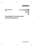
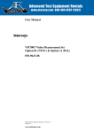
ZS Series controllers have communication functions with external devices. Use this function to
read the data in ZS Series controllers from the host and to write the setting data.
Communication is achieved via the Command and Response Method based on the
CompoWay/F, which is Omron's proprietary communication protocol. Controllers perform
processing according to the command sent from the host, and then return the result to the host
which sent the command as a response.
About Communication Commands
Host
ZS Series Controller (RUN mode)
H
P
L
LD
ON
ZE
RO
EN
AB
LE
Programmable Controller
Personal Computer
Entering Commands
Executing Commands
Controllers are in a
non-measurement state
when executing
commands.
Receives the results of the execution
of commands.
1-2
ZS Series
CompoWay/F Communication Command Reference
Outputs the result of the execution of
commands.
Section 1
Setting the Communication Specifications
Setting the Communication Specifications
1.
Set the mode switch to "FUN"
2.
Select [System] - [Communication] - [Mode] menu.
3.
Select [CompoWay/F].
4.
For RS-232C cable connection, select [System] - [Communication] -
About Communication Commands
Use USB cable or RS-232C cable to connect ZS Series controllers to external
devices.
For USB cable connection, install Smart Monitor ZS and USB driver beforehand. After
installing Smart Monitor ZS, USB ports are recognized as standard COM ports, and
communication is achieved as with the RS-232C. (Setting the communication
specifications including baud rate is not necessary.)
For details on how to connect cable, refer to the User's Manual for each controller.
[RS-232C] menu to set the appropriate communication
specifications for the external device.
5.
Save the settings.
ZS Series
CompoWay/F Communication Command Reference
Section 1
Change the settings of the controller communication specifications for communicating with the
external device by CompoWay/F protocol.
1-3
Section 1
Command Formats
Command Formats
Section 1
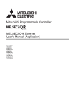
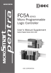
The command format of the communication commands is shown below.
In the following section, items described with "Hex" after numerical values (ex. 02Hex) indicate
hexadecimal numbers. Those described with " " or only with numeral values indicate ASCII
characters.
(Text)
About Communication Commands
STX
02Hex
FIXED
1 byte
NODE No.
(x101 )
(x100 )
2 bytes
Subaddress
SID
"00"
FIXED
"0"
FIXED
2 bytes
1 byte
Command text
MRC
SRC
ETX
BCC
03Hex
FIXED
1 byte
1 byte
BCC calculating range
* In the example format, 1 byte = 1 ASCII character.
Elements
STX
NODE No.
Subaddress
SID (Service ID)
Command text
ETX
BCC
1-4
Details
This is a code to indicate the first part of communication frames (02Hex).
Make sure to set the first byte to 02Hex.
When a controller receives STX while receiving a command, it receives the
command again starting from where it received STX.
This is the Node No. for the identification of the destination.
* About Node No.
It refers to the connection group No. as seen from the host device (PLC). Not
only the ZS Series but other multiple devices are connected to the PLC. The
number assigned to devices connected to a PLC such as this is referred to as a
Node No.
This should be fixed to "00."
This should be fixed to "0."
This is the text part of the command.
"Section 2 – Details of Commands" describes these parts by command.
This is a code to indicate the end of the text (03Hex).
This is a block check character.
The exclusive OR (XOR) of values from Node No. to ETX per byte is BCC.
ZS Series
CompoWay/F Communication Command Reference
Section 1
Command Formats
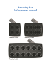
Example of BCC calculation
NODE No.
Subaddress
SID
Command text
"0"
"0"
(30Hex ) (30Hex )
"00"
(3030Hex)
"0"
(30Hex )
"30053001"
(3330303533303031Hex)
ETX
BCC
03Hex 37Hex
Set the result of calculation, which is "37Hex," to BCC.
ZS Series
CompoWay/F Communication Command Reference
1-5
About Communication Commands
<Calculation>
BCC = 30Hex + 30Hex + 30Hex + 30Hex + 30Hex + 33Hex +30Hex + 30Hex +35Hex + 33Hex +
30Hex +30Hex +31Hex +03Hex = 37Hex
"+" indicates the exclusive OR (XOR) operation.
Section 1
STX
02Hex
Section 1
Response Formats
Response Formats
Section 1
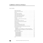
The response format of the communication commands is shown below.
In the following section, items described with "Hex" after numerical values (ex. 02Hex) indicate
hexadecimal numbers. Those described with " " or only with numeral values indicate ASCII
characters.
STX
NODE No.
Subaddress
About Communication Commands
02Hex
1
0
Fixed (×10 ) (×10 )
1 byte
Elements
STX
NODE No.
Subaddress
End code
Response text
ETX
BCC
1-6
2 bytes
End code
"00"
Fixed
2 bytes
Response text
MRC SRC
2 bytes
ETX
BCC
03Hex
Fixed
1 byte 1 byte
Details
Command Formats - page 1 - 4
Refer to the next page.
This is the response text part of the command.
"Section 2 – Details of Commands" describes these parts by command.
Command Formats - page 1 - 4
ZS Series
CompoWay/F Communication Command Reference
Section 1
Response Formats
End codes of responses are shown below.
"10"
"11"
"13"
"14"
"16"
"18"
Details
Normal end
Command error
Command ends successfully.
Specified command is not executed.
Refer to the response code for details of the non-execution.
Parity error
Parity error occurred with any character while receiving a command.
Framing error
Framing error occurred with any character while receiving a
command.
Overrun error
Overrun error occurred with any character while receiving a
command.
BCC error
Received an invalid BCC.
Format error
• Occurs when characters other than 0 to 9 or A to F are used for
command text parts. (Except during echo back tests)
• No SID and command texts exist.
Or no command text exists.
• Either MRC or SRC is missing in the command text.
Subaddress error • Subaddress of the receiving frame is invalid (not supported).
• No subaddress, SID, and command texts exist.
• Subaddress is shorter than two characters, and no SID and
command texts exist.
Frame length error Receiving frame exceeds the supported number of bytes.
About Communication Commands
"12"
Name
Section 1
End
code
"00"
"0F"
One end code is returned after receiving one complete command frame to the node.
No response is made when ETX or BCC characters are missing.
Noises may cause response errors or no response.
Make sure to retry from the host.
It may take three seconds at longest from sending a command to receiving a response. If no
response is returned, make sure to send another command after waiting for more than three
seconds.
ZS Series
CompoWay/F Communication Command Reference
1-7
Section 1
Examples of Abnormal End
Examples of Abnormal End
This section shows the examples of end codes for abnormal ends while receiving commands.
Section 1
y
Invalid subaddress, and no SID and command text exist
Command
STX
NODE No.
Subaddress
02Hex
"0"
"A"
ETX
BCC
03Hex
About Communication Commands
Response
STX
NODE No.
Subaddress
02Hex
"0"
"A"
End code
"1"
"6"
ETX
BCC
03Hex
End code is "16" (Subaddress error).
• This response occurred because subaddress errors are prioritized over format
errors.
y
No command text exists in the command
Command
STX
NODE No.
02Hex
Subaddress
SID
ETX
"0"
"0"
03Hex
"0"
BCC
Response
STX
NODE No.
Subaddress
02Hex
"0"
End code
"0"
"1"
"4"
ETX
BCC
03Hex
End code is "14" (Format error).
y
Node No. is missing
Command
STX
ETX
02Hex
03Hex
BCC
One character is missing for the Node No.
Response
No response is returned.
y
No subaddress exists, and an invalid BCC is used
Command
STX
NODE No.
02Hex
ETX
BCC
03Hex
Err
Response
STX
02Hex
NODE No.
Subaddress
"0"
"0"
End code
"1"
"3"
ETX
03Hex
Subaddress is "00" and end code is "13" (BCC error).
1-8
ZS Series
CompoWay/F Communication Command Reference
BCC
Section 2
Details of Commands
Section 2
2-2
Reading Parameter Areas
2-3
List of Parameter Area Reading Commands
2-3
Commands and Responses
2-4
Writing Parameter Areas
2-6
List of Parameter Area Writing Commands
2-6
Commands and Responses
2-7
Reading Variable Areas
2-9
List of Variable Area Reading Commands
2-9
Commands and Responses
2-9
Reading Controller Information
2-11
Operation Instructions
2-12
List of Operation Instruction Commands
2-12
Commands and Responses
2-12
ZS Series
CompoWay/F Communication Command Reference
2-1
Details of Commands
About General Information of Communication Commands
Section 2
About General Information of Communication Commands
About General Information of Communication Commands
Communication commands are categorized into the groups and meanings as in the following
table:
Groups
Meanings
Pages for
Reference
Section 2
Details of Commands
Reading parameter
areas
System- related
Read setting values related to the target CH system.
Page 2-3
Measurementrelated
Read measurement-related setting values and
results of measurements. Obtain data by specifying
Unit No. and Data No.
Writing parameter
areas
System- related
Write setting values related to the target CH system.
(Refer to Section 3
for Unit No. and Data
No.)
-
Measurementrelated
Write measurement-related setting values and results
of measurements. Write data by specifying Unit No.
and Data No.
(Refer to Section 3
for Unit No. and Data
No.)
Page 2-9
Reading variable areas
Read particular kinds of data in the target CH system.
Reading controller information
Read information on the models connected with a
cable.
Page 2-11
Operation instructions
Operate data of each bank or all banks.
Page 2-12
[Notes on the exchange of communication data]
•
Number of elements indicates the size of data to be exchanged. ASCII character length per
element is determined depending on parameter type codes. Specifically,
8000h to BFFFh : 4 characters per element
From C000h: 8 characters per element
Number of elements = 1 for all commands in this manual. Please enter "8001h" to specify
number of elements.
•
Machine No. indicates channel No. of the destination controller.
•
All data is exchanged in hexadecimal numbers. Therefore, "15" of the decimal number
should be expressed as "0000000Eh." (*1)
•
Distance values should be expressed in the unit of [nm]. Therefore, note that "100
(=00000064h)" indicates "100nm 0.1um" and not 100mm. (*1)
•
Negative values are expressed as the complements of 2. For example, "-100" should be
expressed as "FFFFFF9Ch." (*1)
•
In the case that the measured values such as distance are abnormal values, data parts are
expressed as "7FFFFFFXh" ("X" varies depending on the case.) (*1)
*1: This is an example for 8 characters per element.
2-2
ZS Series
CompoWay/F Communication Command Reference
3
Section 2
Reading Parameter Areas
Reading Parameter Areas
Read parameter areas.
List of Parameter Area Reading Commands
Parameter
Type
Reading start
address
Bank switching
02h
01h
8000h
Keylock
02h
01h
A002h
<Machine No.>
Version
Information
02h
01h
A021h
<Machine No.>
Controller type
Information
02h
01h
A022h
<Machine No.>
RS-232C Data
Length Setting
02h
01h
A030h
RS-232C Parity
Setting
02h
01h
Stop bits setting
02h
Communication
node setting
02h
Digits after
decimal point
<Machine No.>
Specification
of element
Data
Data to be read
Length
numbers
8001h
*2
0 to 3
4
8001h
0 : OFF, 1 : ON
4
8001h
Software Version
4
8001h
0 : ZS-LDC, 1 :
ZS-MDC,
2: ZS-DSU
4
<Machine No.>
8001h
0 : 7 bits, 1 : 8 bits
4
A031h
<Machine No.>
8001h
0 : None,
1 : Odd Number,
2 : Even Number
4
01h
A032h
<Machine No.>
8001h
0 : 1 bit, 1 : 2 bits
4
01h
A033h
<Machine No.>
8001h
0 to 64
4
02h
01h
A040
<Machine No.>
8001h
0 : 1 digit, 1 : 2 digits,
2 : 3 digits,
3 : 4 digits, 4 : 5 digits
4
Digital "Eco"
mode
02h
01h
A041h
<Machine No.>
8001h
0 : NORMAL, 1 : ECO1,
2 : OFF
4
LCD ON/OFF
02h
01h
A042h
<Machine No.>
8001h
0 : OFF, 1 : AUTOOFF,
2 : ON
4
LCD Backlight
02h
01h
A043h
<Machine No.>
8001h
0 : OFF, 1 : AUTOOFF,
2 : ON
4
Sensor Load
02h
01h
A050h
<Machine No.>
8001h
0 : LOAD every time,
1 : SAVE
4
Language
02h
01h
A051h
<Machine No.>
8001h
0 : Japanese,
1 : English
4
Reading
processing unit
data *1
02h
01h
C000h+
<Data
No.>
XXYYh
XX : Unit No.
YY : Machine No.
8000h
+ <No. of
Elements>
Data to be read
8
Details of Commands
SRC
* 1 - All reading/writing operations on processing units are assigned by using this command.
* 2 - Indicates ASCII character length. Refer to page 2-2 for details.
Refer to "Section 3 - Unit No. and Parameter No." for Unit No. and Parameter No.
for each processing unit.
ZS Series
CompoWay/F Communication Command Reference
Section 2
MRC
Data Name
2-3
Section 2
Reading Parameter Areas
Example 1:To read the "language" information from the 2CH controller, assign a command as
follows:
[Machine No.]=0002h
MRC
SRC
02h
01h
Parameter Type
A051h
Reading start
address
Number of
elements
0002h
8001h
Example 2: To read the final measured value from the 1CH controller, assign a command as follows:
Section 2
[Data No.]=20h, [Unit No.]=30h, [Machine No.]=01h
MRC
02h
SRC
01h
Parameter Type
C020h
Reading start
address
Number of
elements
3001
8001h
Details of Commands
Commands and Responses
Command
MRC
SRC
"02"
"01"
2 bytes 2 bytes
Parameter Type
Reading start
address
Number of
elements
4 bytes
4 bytes
4 bytes
Elements
Parameter Type
Details
Specify parameters depending on the data to be obtained.
List of Parameter Area Reading Commands page 2-3
Reading start address
Specify the Machine No. (=CH No.) of the controller to read data by using an ASCII
code expressed in hexadecimal numbers.
Please note that the format of "processing unit data reading" commands is XXYYh
(XX : <Unit No.>, YY : <Machine No.>)
Unit No. and Parameter No. page 3-4
Number of elements
Specify number of elements depending on the Parameter Type.
List of Parameter Area Reading Commands page 2-3
2-4
ZS Series
CompoWay/F Communication Command Reference
5
Section 2
Reading Parameter Areas
Response
MRC
SRC
"02"
"01"
2 bytes 2 bytes
Reading start
address
4 bytes
4 bytes
4 bytes
Data to be read
Details of Commands
4 bytes
Parameter Type
Section 2
Number of
elements
Response Code
Requested data
(depending on commands)
Elements
Details
Response Code
Indicates controller status for the command. Data to be read is not returned when an
error occurs.
Data to be read
Data to be read is expressed by using an ASCII code in hexadecimal numbers.
Data length varies depending on commands.
List of Parameter Area Reading Commands page 2-3
Response code for normal end
Response Code
"0000"
Name
Normal end
Details
No errors.
Response code when an error occurs
Response Code
Error name
Cause
"1001"
Long command length
Command length is too long.
"1002"
Short command length
Command length is too short.
"1003"
Inconsistent number of
elements/data
Number of elements and data do not match.
"1101"
Area type error
Parameter type is wrong.
"1103"
Start address outside of range
error
Reading start address is out of range.
Reading start address specifies the sensor of the
unconnected Machine No.
Bit position is other than "00."
"1104"
End address outside of range
error
Specified number of elements is out of range.
"2203"
Operating error
Reading error.
"2204"
Operating error
Operating mode of sensor is other than RUN.
"2205"
Operating error
Invalid command.
ZS Series
CompoWay/F Communication Command Reference
2-5
Section 2
Writing Parameter Areas
Writing Parameter Areas
Write parameter areas.
List of Parameter Area Writing Commands
Data Name
MRC
SRC
Section 2
Parameter
Type
Writing start
address
Specification
Data to be written
of element
Data
Length
numbers
*2
Bank switching
02h
02h
8000h
<Machine No.>
8001h
0 to 3
4
KEYLOCK
02h
02h
A002h
<Machine No.>
8001h
0 : OFF, 1 : ON
4
RS-232C Data
02h
02h
A030h
<Machine No.>
8001h
0 : 7 bits, 1 : 8 bits
4
02h
02h
A031h
<Machine No.>
8001h
0 : None, 1 : Odd Number,
4
Details of Commands
Length Setting
RS-232C Parity
Setting
2 : Even Number
Stop bits setting
02h
02h
A032h
<Machine No.>
8001h
0 : 1 bit, 1 : 2 bits
4
Communication
02h
02h
A033h
<Machine No.>
8001h
0 to 64
4
02h
02h
A040
<Machine No.>
8001h
0 : 1 digit, 1 : 2 digits, 2 : 3
4
node setting
Digits after
decimal point
digits, 3 : 4 digits, 4 : 5
digits
Digital "Eco" mode
02h
02h
A041h
<Machine No.>
8001h
0 : NORMAL, 1 : ECO1,
4
2 : OFF
LCD ON/OFF
02h
02h
A042h
<Machine No.>
8001h
LCD Backlight
02h
02h
A043h
<Machine No.>
8001h
0 : OFF, 1 : AUTOOFF,
4
2 : ON
0 : OFF, 1 : AUTOOFF,
4
2 : ON
Sensor Load
02h
02h
A050h
<Machine No.>
8001h
0 : LOAD, 1 : SAVE
4
Language
02h
02h
A051h
<Machine No.>
8001h
0 : Japanese, 1 : English
4
Writing processing
02h
02h
C000h+
XXYYh
8000h
Data to be written
8
<Data No.>
XX : Unit No.
+ <No. of
YY : Machine No.
Elements>
unit data *1
* 1 - All reading/writing operations on processing units are assigned by using this command.
* 2 - Indicates ASCII character length. Refer to page 2-2 for details.
Refer to "Section 3 - Unit No. and Parameter No." for Unit No. and Parameter No. for
each processing unit.
Example 1: To turn on the "KEYLOCK" of the 2CH controller, assign a command as follows:
[Machine No.]=0002h, [Data to be written]=0001h
MRC
02h
2-6
SRC
02h
Parameter Type
A002h
Reading start
address
0002h
ZS Series
CompoWay/F Communication Command Reference
Number of
elements
8001h
Data to be written
0001h
7
Section 2
Reading Parameter Areas
Example 2: To set the peak hold mode for the 1CH controller, assign a command as follows:
[Data No.]=02h, [Unit No.]=2Dh, [Machine No.]=01h, [Data to be written]=00000001h
MRC
SRC
02h
02h
Parameter Type
C002h
Writing start
address
2D01
Number of
elements
8001h
Data to be written
00000001h
Section 2
Commands and Responses
Command
Writing start
address
2 bytes 2 bytes
4 bytes
4 bytes
Number of
elements
Data to be written
SRC
"02"
"02"
Details of Commands
Parameter Type
MRC
"8001"
4 bytes
Elements
Parameter Type
4 bytes
Details
Specify parameters depending on the data to be written.
List of Parameter Area Writing Commands page 2-6
Writing start address
Specify the Machine No. (=CH No.) of the controller to write data by using an ASCII
code expressed in hexadecimal numbers.
Please note that the format of "processing unit data writing" commands is XXYYh
(XX : <Unit No.>, YY : <Machine No.>)
Unit No. and Parameter No. page 3-4
Number of elements
Specify number of elements depending on the Parameter Type.
List of Parameter Area Writing Commands page 2-6
Data to be written
Data to be written is specified by using an ASCII code in hexadecimal numbers.
Data length varies depending on commands.
• List of Parameter Area Writing Commands page 2-6
• Do not issue commands other than specified parameter types.
Issuing wrong commands may rewrite internal parameters. In the
case that internal parameters of connected sensors are rewritten,
execute "EEPROM initialization" of operation instruction
commands.
ZS Series
CompoWay/F Communication Command Reference
2-7
Section 2
Writing Parameter Areas
Response
MRC
SRC
"02"
"02"
2 bytes 2 bytes
Response Code
4 bytes
Section 2
Elements
Response Code
Details
Indicates controller status for the command.
Details of Commands
Response code for normal end
Response Code
"0000"
Name
Normal end
Details
No errors.
Response code when an error occurs
Response Code
2-8
Error name
Cause
"1001"
Long command length
"1002"
Short command length
Command length is too short.
"1003"
Inconsistent number of
elements/data
Number of elements and data do not match.
"1100"
Parameter error
Data to be written is out of specified range.
"1101"
Area type error
Parameter type is wrong.
"1103"
Start address outside of range
error
Writing start address is out of range.
Writing start address specifies the sensor of the
unconnected Machine No.
"1104"
End address outside of range
error
Specified number of elements is other than "8001."
"2203"
Operating error
Setting is abnormal.
Refer to the User's Manual of the ZS Series for setting
error conditions of thresholds and the hysteresis width.
"2204"
Operating error
Operating mode of sensor is other than RUN.
"2205"
Operating error
Invalid command.
ZS Series
CompoWay/F Communication Command Reference
Command length is too long.
9
Section 2
Reading Variable Areas
Reading Variable Areas
Read variable areas.
List of Variable Area Reading Commands
Data Name
MRC
SRC
Reading start
address
Bit
position
Number of
elements
Flow data
01h
01h
E1h
0000h
00h
0001h
Measurement
Cycle
01h
01h
81h
<Machine No.>
00h
0002h
Section 2
Variable
Type
[Machine No.]=0002h
MRC
01h
SRC
01h
Variable
Type
81h
Reading start
address
0002h
Bit position
Number of
elements
00h
0002h
Commands and Responses
Command
MRC
SRC
"01"
"01"
Variable
Type
Elements
Bit
position
Number of
elements
"00"
2 bytes 2 bytes 2 bytes
Variable type
Reading start
address
4 bytes
2 bytes
4 bytes
Details
Specify variables depending on the data to be obtained.
List of Variable Area Reading Commands page 2-9
Reading start address
Specify the Machine No. (=CH No.) of the controller to read data by using an ASCII code
expressed in hexadecimal numbers.
Unit No. and Parameter No. page 3-4
Bit position
ZS Series does not support bit access. It is fixed to "00."
Number of elements
Specify number of elements depending on the Variable Type.
List of Variable Area Reading Commands page 2-6
ZS Series
CompoWay/F Communication Command Reference
2-9
Details of Commands
Example: To read the measurement cycle information from the 2CH controller, assign a command as
follows:
Section 2
Reading Variable Areas
Response
MRC
SRC
"01"
"01"
2 bytes 2 bytes
Response Code
Data to be read
4 bytes
Requested number of elements
(depending on commands)
Section 2
Elements
Details
Details of Commands
Response Code
Indicates controller status for the command. Data to be read is not returned when an
error occurs.
Data to be read
Data length is number of elements x 4 ASCII characters. Since the data reading part
of the flow data obtaining commands use special formats, refer to "Section 4: How
to Obtain Flow Data."
Composition of Flow Data Responses page 4-10
Response code for normal end
Response Code
"0000"
Name
Normal end
Details
No errors.
Response code when an error occurs
Response Code
2-10
Error name
Cause
"1001"
Long command length
"1002"
Short command length
Command length is too short.
"1003"
Inconsistent number of
elements/data
Number of elements and data do not match.
"1101"
Area type error
Variable type is wrong.
"1103"
Start address outside of range
error
Reading start address is out of range.
Reading start address specifies the sensor of the
unconnected Machine No.
Bit position is other than "00."
"1104"
End address outside of range
error
Specified number of elements is out of range.
"2203"
Operating error
Reading error.
"2204"
Operating error
Operating mode of sensor is other than RUN.
"2205"
Operating error
Invalid command.
ZS Series
CompoWay/F Communication Command Reference
Command length is too long.
11
Section 2
Reading Controller Information
Reading Controller Information
Read data about ZS Series types and so on.
Command
SRC
"05"
"01"
Section 2
MRC
2 bytes 2 bytes
Details of Commands
Response
MRC
SRC
"05"
"01"
2 bytes 2 bytes
Response Code
Model
Version
4 bytes
20 bytes
20 bytes
Elements
Details
Response Code
Indicates controller status for the command. Data to be read is not returned when an
error occurs.
Model
Model is expressed with 20 ASCII characters.
Version
Version is expressed with 20 ASCII characters.
Response code for normal end
Response Code
"0000"
Name
Normal end
Details
No errors.
Response code when an error occurs
Response Code
Error Name
Cause
"1001"
Long command length
Command length is too long.
"1002"
Short command length
Command length is too short.
ZS Series
CompoWay/F Communication Command Reference
2-11
Section 2
Operation Instructions
Operation Instructions
Provides operation instructions to controllers.
List of Operation Instruction Commands
Instruction Name
MRC
Section 2
Complete INIT
SRC
30h
05h
Instruction
Code
55h
Related
Information 1
<Machine No.>
Related
Information 2
0000h
DATA SAVE
30h
05h
57h
<Machine No.>
0000h
CLEAR
30h
05h
58h
<Machine No.>
0000h
Details of Commands
CLEAR (which clears banks) initializes current banks' sensing settings and measurement settings.
Settings of other banks and system settings are not initialized.
Complete INIT initializes all settings (settings of all banks and system settings).
Example: To execute Complete INIT of the 2CH controller, assign a command as follows:
[Related information1]=02h
MRC
30h
SRC
05h
Instruction
Code
55h
Related
Information 1
Related
Information 2
02h
0001h
Commands and Responses
Command
MRC
SRC
"30"
"05"
2 bytes 2 bytes
Instruction
Code
Information 1
2 bytes
2 bytes
Related
Related Information 2
4 bytes
Elements
2-12
Details
Instruction Code
Specify commands depending on the instruction to be executed.
Related Information 1
Specify the channel No. of the controller related to the command.
Example: In the case of 2CH, specify "02."
Related Information 2
Usually, setting other than "0000" is not accepted.
ZS Series
CompoWay/F Communication Command Reference
13
Section 2
Operation Instructions
Response
MRC
SRC
"30"
"05"
2 bytes
2 bytes
Response Code
Instruction
Code
Information 1
Related
Information 2
4 bytes
2 bytes
2 bytes
4 bytes
Related
Section 2
Elements
Details
Indicates controller status for the command.
Instruction Code
The code which is the same as the transmitted will be returned.
Details of Commands
Response Code
Related Information 1
Related Information 2
Response code for normal end
Response Code
"0000"
Name
Normal end
Details
No errors.
Response code when an error occurs
Response Code
Error Name
Cause
"1001"
Long command length
"1002"
Short command length
Command length is too long.
Command length is too short.
"1101"
Area type error
Instruction code is invalid.
"1103"
Start address outside of range
error
Related information specifies the sensor of the
unconnected Machine No.
"2203"
Operating error
Setting is abnormal.
Refer to the User's Manual of the ZS Series for error
conditions.
"2204"
Operating error
Operating mode of sensor is other than RUN.
"2205"
Operating error
Invalid command.
ZS Series
CompoWay/F Communication Command Reference
2-13
Section 2
Operation Instructions
MEMO
Section 2
Details of Commands
2-14
ZS Series
CompoWay/F Communication Command Reference
Section 3
Unit No. and Parameter No.
3-2
Setting Value Obtaining and Changing Command
3-4
Parameter List (ZS-LDC)
Section 3
Measurement Result Obtaining Command
3-4
3-11
Parameter List (ZS-MDC)
3-18
Parameter List (ZS-DSU)
3-27
ZS Series
CompoWay/F Communication Command Reference
Unit No. and Parameter No.
Parameter List (ZS-HLDC)
3-1
Section 3
Measurement Result Obtaining Command
Measurement Result Obtaining Command
Parameter List (ZS-LDC)
When selecting a mode other than “THICK/GAP - FILM/OTHERS - TRANSFER" mode
(when no 2-area measurement is performed):
Unit No.
30h
Data No.
20h
Parameter Description
Measurement result (=Main digital display value)
When selecting “THICK/GAP - FILM/OTHERS - TRANSFER" mode
(when a 2-area measurement is performed):
Section 3
Unit No.
30h
44h
Data No.
20h
58h
Parameter
Area 1 displacement value (TASK1)
Area 2 displacement value (TASK2)
Thickness and/or Gap results
(=Main digital display value = TASK3 = Area1 –
Area2)
Unit No. and Parameter No.
Parameter List (ZS-HLDC)
For single task mode
When selecting a mode other than "GLASS/MODE 2" or "GLASS THICKNESS/MODE 2"
mode
(when no 2-area measurement is performed):
Unit No.
30h
Data No.
20h
Parameter Description
Measurement result (=Main digital display value)
When selecting "GLASS/MODE 2" or "GLASS THICKNESS/MODE 2" mode
(when a 2-area measurement is performed):
Unit No.
30h
44h
Data No.
20h
58h
Parameter
Area 1 displacement value (TASK1)
Area 2 displacement value (TASK2)
Glass surface and/or Glass thickness results
(=Main digital display value = TASK3 = Area1 –
Area2)
For multi-task mode
Unit No.
30h
44h
58h
6Ch
3-2
Data No.
20h
Parameter
TASK1 measurement result
TASK2 measurement result
TASK3 measurement result
TASK4 measurement result
ZS Series
CompoWay/F Communication Command Reference
Section 3
Measurement Result Obtaining Command
Parameter List (ZS-MDC)
Unit No.
30h
44h
58h
6Ch
Data No.
20h
Parameter
TASK1 measurement result
TASK2 measurement result
TASK3 measurement result
TASK4 measurement result
Example1: When obtaining a measurement result of ZS-LDC (2CH) (and when no 2-area
measurement is performed):
02h
01h (C000h + 20h (Data No.)) 30h (Unit No.) 02h (CH No.) (8000h + 1h (Number of elements))
In the command section, the value is shown as below:
02h 01h C020h 3002h 8001h
To this command, if the response is shown as below:
It indicates as 80500000nm (= 80.5mm) because 04CC5520h = 80500000.
Example2: When obtaining a displacement value of a standalone ZS-LDC (0CH) Area2 (and a
02h
01h (C000h + 20h (Data No.)) 44h (Unit No.) 00h (CH No.) (8000h + 1h (Number of elements))
In the command section, the value is shown as below:
02h 01h C020h 4400h 8001h
To this command, if the response is shown as below:
02h 01h C020h 4400h 8001h 02719C40h
It indicates as 41000000nm (= 41mm) because 02719C40h = 41000000.
Example3: When obtaining a measurement result of ZS-MDC (0CH) TASK3:
02h
01h (C000h + 20h (Data No.)) 58h (Unit No.) 00h (CH No.) (8000h + 1h (Number of elements))
In the command section, the value is shown as below:
02h 01h C020h 5800h 8001h
To this command, if the response is shown as below:
02h 01h C020h 5800h 8001h FFF0BDC0h
It indicates as -1000000nm (= -1mm) because FFF0BDC0h = -1000000.
(A negative value is expressed as a complement of two.)
ZS Series
CompoWay/F Communication Command Reference
3-3
Unit No. and Parameter No.
2-area measurement is performed):
Section 3
02h 01h C020h 3002h 8001h 04CC5520h
Section 3
Setting Value Obtaining and Changing Command
Setting Value Obtaining and Changing Command
Parameter List (ZS-LDC)
Sensing Setting (common for all TASKs)
Data
No.
00h
Measurement mode
12h
Exposure time
13h
14h
Number of additional
lines
Line skipping
01h
00h
Head installation
0: DIFFUSE
1: REGULAR
02h
00h
LD power mode
02h
Surface to be controlled
for light amount
06h
LD power when fixed
0Dh
Lower limit of LD power
0Eh
Upper limit of LD power
25h
Incident level
(First surface)
Incident level
(Second surface)
Incident level
(Third surface)
0: Auto
1: Auto range
2: Fixed
0: Peak
1: Surface
2: Second surface
3: Third surface
0 to 1000
(1div:0.1%)
0 to 800
(1div:0.1%)
0 to800
(1div:0.1%)
0 to 4095 (tone)
Unit No.
00h
Section 3
Unit No. and Parameter No.
26h
27h
03h
3-4
Parameter
00h
Measurement object
01h
Glass material
02h
Glass thickness
measurement mode
ZS Series
CompoWay/F Communication Command Reference
Setting range/
output range
0: STANDARD
1: HI-RESO
2: HI-SPEED
3: HI-SENS
4: CUSTOM
2 to 200
(1div:0.1ms)
1 to 200
Remarks
Parameters when
[Measurement mode]=[Custom]
0: ON
1: OFF
(Note 1)
Parameters when [Emitted light
amount setting]=[Fixed]
Parameters when [Emitted light
amount setting]=[Auto range]
0 to 4095 (tone)
0 to 4095 (tone)
0: NORMAL
1: PCB
2: MIRROR
3: GLASS
4: THICKNESS
5: GAP
0: NORMAL
1: FILM/OTHERS
0: STOP
1: Moving
Parameters when
[Measurement
object]=[Thickness] or [Gap]
Parameters when [Glass
material]=[FILM/ OTHERS]
Section 3
Setting Value Obtaining and Changing Command
Unit No.
03h
Data
No.
03h
Image smoothing level
04h
Background removing
level before addition
Background removing
level after addition
Edge threshold
05h
06h
0: None
1: Filter size 2
2: Filter size 4
3: Filter size 8
4: Filter size 16
0 to 255 (tone)
0 to 4095 (tone)
0: 0 %
1: 12.5 %
2: 25%
3: 37.5 %
4: 50%
5: 62.5 %
6: 75%
7: 87.5 %
01h
Mutual interference
prevention mode
Timing setting
0: OFF
1: ON
0: Timing A
1: Timing B
05h
00h
Gain setting
1 to 5
07h
00h
LD power mode (Area 1)
02h
Surface to be controlled
for light amount
06h
LD power when fixed
0Dh
Lower limit of LD power
0: Auto
1: Auto range
2: Fixed
0: Peak
1: Surface
2: Second surface
3: Third surface
0 to 1000
(1div:0.1%)
0 to 800
(1div:0.1%)
0Eh
Upper limit of LD power
0 to 800
(1div:0.1%)
11h
Measurement target area
0: Surface
1: Second surface
2: Third surface
25h
Incident level
(First surface)
Incident level
(Second surface)
Incident level
(Third surface)
0 to 4095 (tone)
26h
27h
Remarks
Unit No. and Parameter No.
00h
Setting range/
output range
Section 3
04h
Parameter
Parameters when [Mutual
interference prevention
mode]=[ON]
(Note 1)
Parameters when [Emitted light
amount setting]=[Fixed]
Parameters when [Emitted light
amount setting]=[Auto range]
0 to 4095 (tone)
0 to 4095 (tone)
ZS Series
CompoWay/F Communication Command Reference
3-5
Section 3
Setting Value Obtaining and Changing Command
Unit No.
08h
Data
No.
00h
Parameter
LD power mode (Area 2)
Section 3
Unit No. and Parameter No.
02h
Surface to be controlled
for light amount
06h
LD power when fixed
0Dh
Lower limit of LD power
0Eh
Upper limit of LD power
11h
Measurement target area
25h
Incident level
(First surface)
Incident level
(Second surface)
Incident level
(Third surface)
26h
27h
Setting range/
output range
0: Auto
1: Auto range
2: Fixed
0: Peak
1: Surface
2: Second surface
3: Third surface
0 to 1000
(1div:0.1%)
0 to 800
(1div:0.1%)
0 to 800
(1div:0.1%)
0: Surface
1: Second surface
2: Third surface
0 to 4095 (tone)
Remarks
(Note 1)
Parameters when [Emitted light
amount setting]=[Fixed]
Parameters when [Emitted light
amount setting]=[Auto range]
0 to 4095 (tone)
0 to 4095 (tone)
Note 1: When no 2-area measurement is performed, Unit No. 2 is valid and Unit No. 7 and 8 are invalid.
When a 2-area measurement is performed, Unit No. 2 is invalid and Unit No. 7 and 8 are valid.
Example 1: When reading the setting values of edge threshold (when LDC is 1CH):
Since the edge threshold for Unit No. is 03h, and Data No. is 06h, values are shown as below:
02h
01h (C000h + 06h (Data No.)) 03h (Unit No.) 01h (CH No.) (8000h + 1h (Number of elements))
In the command section, the value is shown as below:
02h 01h C006h 0301h 8001h
To this command, if the response is shown as below:
02h 01h C006h 0301h 8001h 00000004h,
It indicates 50 % because the value is 4.
Example 2: When changing the gain setting to 3 (when ZS-LDC is 0CH):
Since the gain setting for Unit No. is 05h, and Data No. is 00h, values are shown as below:
02h
02h (C000h + 00h (Data No.)) 05h (Unit No.)
00h (CH No.)
and (8000h + 1h (Number of Elements)) 00000003h (Data to be written),
In the command section, the value is shown as below:
02h 02h C000h 0000h 8001h 00000003h
To this command, if the response is shown as below:
02h 02h 0000h
It indicates a normal end.
3-6
ZS Series
CompoWay/F Communication Command Reference
Section 3
Setting Value Obtaining and Changing Command
Measurement Setting 1 (Settings per TASK) (Note 2)
Unit No.
(Note 3)
29h
Data
No.
00h
Scaling mode
01h
Span value
0: OFF
1: ON
-20000 to 20000 (X0.0001)
02h
Offset value
-999999999 to 999999999 (nm)
2Ah
02h
Smooth
0: OFF
1: ON
2Bh
02h
Average number of times
0: 1 time
1: 2 times
2: 4 times
3: 8 times
4: 16 times
5: 32 times
6: 64 times
7: 128 times
8: 256 times
9: 512 times
10: 1024 times
11: 2048 times
12: 4096 times
2Ch
02h
Differential mode
03h
Differentiation cycles
0: OFF
1: ON
1 to 5000 (ms)
02h
Hold type
03h
Trigger method
04h
Trigger level
0: OFF
1: PEAK
2: BOTTOM
3: P-P
4: AVERAGE
5: SAMPLE
0: External
1: Self-up trigger
2: Self-down trigger
-999999999 to 999999999 (nm)
05h
Trigger hysteresis
0 to 999999999 (nm)
06h
Trigger delay (ms)
0 to 5000 (ms)
30h
Remarks
07h
Sampling period (ms)
1 to 5000 (ms)
08h
Trigger delay mode
0: OFF
1: ON
05h
-999999999 to 999999999 (nm)
07h
Offset value for zero
reset
Zero reset mode
02h
03h
LOW threshold value
HIGH threshold value
Unit No. and Parameter No.
2Eh
Setting range/output range
Section 3
2Dh
Parameter
0: REAL
1: HOLD
-999999999 to 999999999 (nm)
-999999999 to 999999999 (nm)
ZS Series
CompoWay/F Communication Command Reference
3-7
Section 3
Setting Value Obtaining and Changing Command
(Note 2)
The same task as MDC is performed as internal processing when selecting a “THICK/GAP FILM/OTHERS - TRANSFER” mode (when a 2-area measurement is performed).
Processing is assigned to each task as below:
When 2-area measurement is
performed (*3)
Calculates Area 1 displacement value
Calculates Area 2 displacement value
Calculates the difference
(=Thickness/gap)
between TASK 1 and TASK 2
Unused (*2)
TASK1
TASK2
TASK3
TASK4
When measurement other than 2-area
measurement is performed
Measurement result (*1)
Unused (*2)
Unused (*2)
Unused (*2)
*1: The result is a thickness distance value when the thickness measurement is set.
Section 3
Other than the above, the result is a surface distance value.
*2: An error always occurs.
*3: Only TASK3 can be displayed or set on the controller.
(Note 3)
The Unit No. here indicates TASK 1 Unit No.
Unit No. and Parameter No.
Unit No. other than the above, such as TASK2 or a later one, can be calculated by adding (TASK
number -1) to the Unit No. and multiplying it by 14h for another reference or setting.
Example1: When reading the setting values of the average number of times (when ZS-LDC is
1CH, and no 2-area measurement is performed):
Since the average number of times is 2Bh for Unit No., and 02h for Data No., values are shown as
below:
02h
01h (C000h + 02h (Data No.)) 2Bh (Unit No.) 01h (CH No.) (8000h + 1h (Number of elements))
In the command section, the value is shown as below:
02h 01h C002h 2B01h 8001h
To this command, if the response is shown as below:
02h 01h C002h 2B01h 8001h 00000004h
Since the value is 4, this indicates 16 times.
Example 2: When changing a high threshold value for the result of thickness to 100 mm (when
ZS-LDC is 0CH, and a 2-area measurement is performed):
The thickness result is calculated by using TASK3 when performing a 2-area measurement.
Usually, the high threshold value is 30h for Unit No., and 03h for Data No.
However, Unit No. is 58h (= 30h + (3-1) x 14h) because TASK3 is set this time.
Besides, 100mm thickness is expressed as 05F5E100h in a hexadecimal number because 100 mm is
100,000,000nm.
02h
02h (C000h + 03h (Data No.)) 58h (Unit No.)
00h (CH No.)
and (8000h + 1h (Number of Elements)) 05F5E100h (Data to be written)
In the command section, the value is shown as below:
02h 02h C003h 5800h 8001h 05F5E100h
To this command, if the response is shown as below:
02h 02h 0000h
It indicates a normal end.
3-8
ZS Series
CompoWay/F Communication Command Reference
Section 3
Setting Value Obtaining and Changing Command
Measurement Setting 2 (common to all TASKs)
Unit No.
78h
79h
Parameter
Non-measurement settings
01h
Output at CLAMP
00h
Hysteresis width
01h
Timer mode
Delay time
02h
03h
05h
06h
07h
08h
Monitor focus mode
Monitor focus
distance value 1
Monitor focus
distance value 2
Monitor focus current value 1
Monitor focus current value 2
Monitor focus voltage value 1
Monitor focus voltage value 2
04h
Input polarity of external input 0
05h
06h
Input polarity of external input 1
Input polarity of external input 2
F0h
0: OFF, 1: ON
-999999999 to 999999999 (nm)
(Note 4)
-999999999 to 999999999 (nm)
4 to 20 (mA)
4 to 20 (mA)
-10 to 10 (V)
-10 to 10 (V)
Unit No. and Parameter No.
7Fh
Remarks
0: OFF
1: OFF DELAY
2: ON DELAY
3: 1 shot
1 to 5000 (ms)
02h
04h
7Eh
Setting range/output range
0: Keep
1: Clamp
0: MAX
1: 20mA
2: 12mA
3: 4mA
4: MIN
0 to 999999999 (nm)
Section 3
7Ah
Data No.
00h
0: L active
1: H active
07h
Input polarity of external input 3
01h
06h
External Input (IN) function
mode
Digital output target
0Ah
External input 0 mode
0Bh
External input 1 mode
0Ch
External input 2 mode
0Dh
External Input 3 mode
08h
External input mode
0: STANDARD
2: Parallel input OFF mode
C0h
Timing input
C1h
Reset input
C2h
LD-OFF input
C3h
Zero-reset execution
0: OFF
1: ON
0: OFF
1: ON
0: OFF
1: ON
1: Execution
C4h
Zero-reset cancel
1: Cancel
0: Standard
1: Bank
0: OFF
1: ON
0: Not used
1: Trigger
2: Hold reset
3: Laser OFF
4: Zero-reset
(Note 5)
(Note 6)
ZS Series
CompoWay/F Communication Command Reference
3-9
Section 3
Setting Value Obtaining and Changing Command
(Note 4)
To change the monitor focus setting, monitor focus mode must be ON.
For example, to change the current setting of the monitor focus, change parameters below:
-
Monitor focus mode (ON)
-
Monitor focus distance value 1
-
Monitor focus distance value 2
-
Monitor focus current value 1
-
Monitor focus current value 2
In addition, set outputs (current and voltage), which are set by the analog output switch in the
controller.
(Note 5)
Section 3
External input 0 mode and External input 1 mode settings cannot be changed because they
automatically function as bank inputs when the bank mode is used (when “external input (IN) function
mode” is set to “bank”).
(Note 6)
Unit No. and Parameter No.
When the external input mode is set to “STANDARD”, the controller enters into the status below:
*
External input of the controller is enabled,
*
Commands from timing input to zero-resetting are disabled.
When the external input mode is set to “Parallel input OFF”, the controller enters into the status below:
*
External input of the controller is enabled,
*
Commands from timing input to zero-resetting are disabled.
Therefore, to send a command related to inputs, the external input mode should be set to “Parallel
input OFF.”
Once ON is written to the timing input, reset input, and LD-OFF input parameters, the ON state is kept
until OFF is written next.
Controller operates in the same manner as the input state is kept ON.
However, special care shall be taken because the operation changes depending on the state of
external input line to the controller when the external input mode is set back to the “standard mode.”
Operations are performed depending on the settings when “Execution” or “Cancel” is written to the
parameter with respect to the zero-reset.
Example 1: To perform zero-reset (when ZS-LDC is 1CH):
The command sending sequence is as follows:
(1) Write “parallel input OFF mode” to the “external input mode” parameter.
(2) Write “execution” to the “zero-reset execution” parameter.
(3) Write “STANDARD” to the “external input mode” parameter.
An actual example of a command procedure is shown below:
(1) 02h 02h C008h F001h 8001h 00000002h
(2) 02h 02h C0C3h F001h 8001h 00000001h
(3) 02h 02h C008h F001h 8001h 00000000h
Writing commands (1) and (3) above before and after the input-related operation command,
respectively, is recommended.
3-10
ZS Series
CompoWay/F Communication Command Reference
Section 3
Setting Value Obtaining and Changing Command
Parameter List (ZS-HLDC)
Sensing Setting (common for all TASKs)
Unit No.
0h
Data No.
0h
Parameter
Measurement mode
End position of area 1
0 to 639 (pix)
Dh
Start line of area 1
Fh
End line of area 1
18h
Start position of area 2
0 to (Number of additional lines 1)
0 to (Number of additional lines 1)
0 to 639 (pix)
1Ah
End position of area 2
0 to 639 (pix)
19h
Start line of area 2
1Ah
End line of area 2
12h
Exposure time
13h
Number of additional
lines
14h
Line skipping
16h
2-area mode
17h
Compensation mode
20h
C0h
0 to (Number of additional lines 1)
0 to (Number of additional lines 1)
2 to 200 (1div:0.1ms)
When multi-task mode is OFF
5 to 200 (1div:0.1ms)
When multi-task mode is ON
1 to 200
When multi-task mode is OFF
8 to 200
When multi-task mode is ON
0: OFF
1: ON
0: OFF
1: ON
0: OFF
1: Start position compensation
2: End position compensation
3: Start/end position compensation
112 to 20000 (us)
1: Execute teach
1h
C1h
0h
Measurement cycle
Reference point teach for
compensation mode
2-area teach
Head installation
2h
0h
LD power mode
When multi-task
mode is ON
Unit No. and Parameter No.
Start position of area 1
Eh
Measurement mode
Remarks
When multi-task
mode is OFF
Section 3
Ch
Setting range/output range
0: STANDARD
1: HI-RESO
2: HI-SPEED
3: HI-SENS
4: CUSTOM
1: STANDARD
2: HI-RESO
3: HI-SENS
4: CUSTOM
0 to 639 (pix)
Parameters for
CUSTOM mode
1: Execute teach
0: Diffuse
1: Regular
0: Auto
1: Auto-scale
2: Fixed
ZS Series
CompoWay/F Communication Command Reference
3-11
Section 3
Setting Value Obtaining and Changing Command
Unit No.
2h
Data No.
2h
Parameter
Surface to be controlled
for light amount
6h
Dh
Eh
20h
24h
25h
LD power when fixed
Lower limit of LD power
Upper limit of LD power
Incident level
LD power
Incident level
(First surface)
Incident level
(Second surface)
Incident level
(Third surface)
Measuring object
26h
Section 3
27h
3h
0h
Unit No. and Parameter No.
2h
3h
4h
6h
4h
0h
1h
5h
28h
3-12
0h
0h
GLASS/GLASS
THICKNESS mode
Image smoothing level
Background removing
level before addition
Edge threshold
Mutual interference
prevention mode
Mutual interference
prevention timing
Gain setting
Measurement mode
Setting range/output range
0: Peak
1: First surface
2: Second surface
3: Third surface
0 to 800 (1div:0.1%)
0 to 800 (1div:0.1%)
0 to 800 (1div:0.1%)
0 to 4095 (1div:0.1%)
0 to 800 (1div:0.1%)
0 to 4095 (1div:0.1%)
Remarks
0 to 4095 (1div:0.1%)
0 to 4095 (1div:0.1%)
0: Normal
1: PCB
2: Mirror
3: Glass
4: Glass thickness
0: Mode 1
1: Mode 2
0: No filter
1: Filter size 2
2: Filter size 4
3: Filter size 8
4: Filter size 16
0 to 255 (tone)
0: 0%
1: 12.5%
2: 25%
3: 37.5%
4: 50%
5: 62.5%
6: 75%
7: 87.5%
0: OFF
1: ON
0: Timing A
1: Timing B
1 to 5
0: OFF
1: Average
2: Peak
3: Bottom
4: Thickness
5: Gap
6: K+mX;+nY
ZS Series
CompoWay/F Communication Command Reference
When the
measurement object
is changed, the
settings are
initialized according
to the selected
object.
TASK1 settings.
The settings in Unit
Number 28h are
valid only for
multi-task mode.
Section 3
Setting Value Obtaining and Changing Command
Unit No.
Data No.
3h
Parameter
Parameter X
28h
4h
Parameter Y
Parameter M
-100 to 100 (1div:0.1%)
9h
Parameter N
-100 to 100 (1div:0.1%)
1h
Surface for
measurement (Area 1)
Ah
Surface for
measurement (Area 2)
Bh
Measurement position 1
(for thickness
measurement)
Ch
Measurement position 2
(for thickness
measurement)
Dh
Measurement area
Eh
Width of peak bottom
0: First surface
1: Second surface
2: Third surface
0: First surface
1: Second surface
2: Third surface
0: None
1: Average
2: Peak
3: Bottom
0: None
1: Average
2: Peak
3: Bottom
0: Area 1
1: Area 2
0 to 255
20h
0h
Measurement value
(First surface)
Measurement value
(Second surface)
Measurement value
(Third surface)
Scaling mode
1h
Span value
0: OFF
1: ON
-20000 to 20000 (1div:0.0001)
2h
Offset value
-999999999 to 999999999 (nm)
2h
Smooth
0: OFF
1: ON
21h
22h
29h
2Ah
Unit No. and Parameter No.
Parameter K
8h
Remarks
Section 3
5h
Setting range/output range
0: None
1: TASK1
2: TASK2
3: TASK3
4: TASK4
0: None
1: TASK1
2: TASK2
3: TASK3
4: TASK4
-999999999 to 999999999
- (nm)
- (nm)
- (nm)
TASK1 settings.
ZS Series
CompoWay/F Communication Command Reference
3-13
Section 3
Setting Value Obtaining and Changing Command
Section 3
Data No.
2h
Parameter
Average
2Ch
2h
Differential
2Dh
3h
2h
Differentiation cycles
Hold type
3h
Trigger method
4h
5h
6h
7h
8h
Trigger level
Trigger hysteresis
Trigger delay (ms)
Sampling time (ms)
Trigger delay mode
5h
7h
Offset at zero reset
Zero reset mode
40h
Status
Unit No. and Parameter No.
Unit No.
2Bh
2Eh
3-14
Setting range/output range
0: 1 time
1: 2 times
2: 4 times
3: 8 times
4: 16 times
5: 32 times
6: 64 times
7: 128 times
8: 256 times
9: 512 times
10: 1024 times
11: 2048 times
12: 4096 times
0: OFF
1: ON
1 to 5000 (ms)
0: Through
1: Peak
2: Bottom
3: Peak to peak
4: Average
5: Sampling
0: External input
1: Self up
2: Self down
-999999999 to 999999999 (nm)
0 to 999999999 (nm)
0 to 5000 (ms)
1 to 5000 (ms)
0: OFF
1: ON
-999999999 to 999999999 (nm)
0: Real
1: Hold
0: OFF
1: ON
ZS Series
CompoWay/F Communication Command Reference
Remarks
Section 3
Setting Value Obtaining and Changing Command
(*)
If GLASS/MODE 2 or GLASS THICKNESS/MODE 2 is selected, a process using multiple tasks will be
performed, as in multi-task mode.
The following processes are assigned to the respective tasks:
TASK1
Calculates Area 1 displacement value
TASK2
Calculates Area 2 displacement value
GLASS: Calculates the result of the NEAR side of TASK 1 and TASK 2.
TASK3
GALSS THICKNESS: Calculates the difference value between TASK1 and
TASK2.
TASK4
Unused
The measurement conditions can be set for each task in this mode.
Data No.
Parameter
Setting range/output range
78h
0h
Hysteresis width
0 to 999999999 (nm)
1h
Timer mode
0: OFF
1: OFF-Delay
2: ON-Delay
3: One shot
2h
Delay time
1 to 5000 (ms)
3h
Judgment output TASK
0: TASK1
1: TASK2
2: TASK3
3: TASK4
79h
0h
Non-measurement settings
0: Keep
1: Clamp
7Ah
2h
Monitor focus mode
0: OFF, 1: ON
3h
Monitor focus distance value 1
-999999999 to 999999999 (nm)
4h
Monitor focus distance value 2
-999999999 to 999999999 (nm)
5h
Monitor focus current value 1
4 to 20 (mA)
6h
Monitor focus current value 2
4 to 20 (mA)
7h
Monitor focus voltage value 1
-10 to 10 (V)
8h
Monitor focus voltage value 2
-10 to 10 (V)
15h
Output mode TASK
When multi-task mode is OFF
0: OFF
1: ON
When multi-task mode is ON
0: OFF
1: TASK1
2: TASK2
3: TASK3
Remarks
ZS Series
CompoWay/F Communication Command Reference
Unit No. and Parameter No.
Setting
judgment
process
Section 3
Unit No.
3-15
Section 3
Setting Value Obtaining and Changing Command
Data No.
Parameter
7Ah
17h
Output at CLAMP
Voltage output
0: MAX
1: 10V
2: 9V
3: 8V
4: 7V
5: 6V
6: 5V
7: 4V
8: 3V
9: 2V
10: 1V
11: 0V
12: -1V
13: -2V
14: -3V
15: -4V
16: -5V
17: -6V
18: -7V
19: -8V
20: -9V
21: -10V
22: MIN
Current output
0: MAX
1: 20mA
2: 19mA
3: 18mA
4: 17mA
5: 16mA
6: 15mA
7: 14mA
8: 13mA
9: 12mA
10: 11mA
11: 10mA
12: 9mA
13: 8mA
14: 7mA
15: 6mA
16: 5mA
17: 4mA
7Bh
Digital
Output
2h
Monitor focus mode
0: OFF, 1: ON
3h
Monitor focus distance value 1
-999999999 to 999999999 (nm)
4h
Monitor focus distance value 2
-999999999 to 999999999 (nm)
5h
Monitor focus current value 1
0 to 65535
6h
Monitor focus current value 2
0 to 65535
7h
Clear Monitor Focus
1: Clear
8h
Output at CLAMP
0 to 65535
Section 3
Unit No.
Unit No. and Parameter No.
3-16
ZS Series
CompoWay/F Communication Command Reference
Setting range/output range
Remarks
Section 3
Setting Value Obtaining and Changing Command
Unit No.
Data No.
7Bh
Digital
Output
Ah
Output TASK(When the
measurement value is output)
Bh
Output mode
Ch
Update cycle
5h
Mode
0: OFF
1: ON
3h
Buffering period
1 to 65535
4h
Buffer size per item of data
1 to 1000
Eh
TASK1
0: OFF
1: ON
Fh
TASK2
0: OFF
1: ON
10h
TASK3
0: OFF
1: ON
11h
TASK4
0: OFF
1: ON
0h
Output TASK
6h
Mode
0: TASK1
1: TASK2
2: TASK3
3: TASK4
0: OFF
1: ON
4h
5h
6h
Input 0
Input 1
Input 2
7h
8h
Input 3
External input mode
9h
Control TASK setting
7Ch
Logging
Remarks
0: TASK1
1: TASK2
2: TASK3
3: TASK4
4: Consecutively
0: OFF
1: Measurement value
2: Judgment
1 to 100
When
multi-task
mode is ON
Unit No. and Parameter No.
F0h
Parallel
Input
Setting range/output range
Section 3
7Eh
Link
Parameter
0: Low Active
1: High Active
0: Normal mode
1: Bank switching mode
2: Parallel IN off mode
0: TASK1
1: TASK2
2: TASK3
3: TASK4
ZS Series
CompoWay/F Communication Command Reference
3-17
Section 3
Setting Value Obtaining and Changing Command
Parameter List (ZS-MDC)
Input Setting (common to all TASKs)
Unit No.
00h
Data No.
00h
09h
0Ah
0Bh
0Ch
0Dh
0Eh
0Fh
10h
11h
20h
21h
Parameter
Data A input
destination CH
Data B input
destination CH
Data C input
destination CH
Data D input
destination CH
Data E input
destination CH
Data F input
destination CH
Data G input
destination CH
Data H input
destination CH
Data I input
destination CH
Data A input mode
Data B input mode
Data C input mode
Data D input mode
Data E input mode
Data F input mode
Data G input mode
Data H input mode
Data I input mode
Obtained result A
Obtained result B
22h
Obtained result C
23h
Obtained result D
24h
Obtained result E
25h
Obtained result F
26h
Obtained result G
27h
Obtained result H
28h
Obtained result I
01h
02h
03h
04h
Section 3
05h
06h
Unit No. and Parameter No.
07h
08h
3-18
ZS Series
CompoWay/F Communication Command Reference
Setting range/output range
0 to 11 (CH)
Remarks
0: OFF
1: ON
-999999999 to 999999999
(nm)
Read only
Section 3
Setting Value Obtaining and Changing Command
Example 1: When assigning (writing) input A to CH3:
To assign input A to CH3, input destination CH of data A should be set to 3CH and input mode of data
A should be ON.
(1) For input destination CH of data A, both Unit No. and Data No. are 00h.
(2) For input mode of data A, Unit No. and Data No. are 00h and 09h, respectively.
Therefore, commands to be sent are shown as below:
(1) When 02h
02h (C000h + 00h (Data No.)) 00h(Unit No.) 00h (CH No.),
and (8000h + 1h (Number of Elements)) 00000003h (Data to be written),
Command is: 02h 02h C000h 0000h 8001h 00000003h.
To this command, if the response is shown as below:
02h 02h 0000h
It indicates a normal end.
Section 3
(2) In the same manner as above,
When 02h
02h (C000h + 09h (Data No.)) 00h(Unit No.) 00h (CH No.),
and (8000h + 1h (Number of Elements)) 00000001h (Data to be written),
Command is: 02h 02h C009h 0000h 8001h 00000001h.
Unit No. and Parameter No.
To this command, if the response is shown as below:
02h 02h 0000h
It indicates a normal end.
ZS Series
CompoWay/F Communication Command Reference
3-19
Section 3
Setting Value Obtaining and Changing Command
Measurement Setting 1 (Setting per TASK)
Unit No.
(Note 1)
28h
Section 3
Unit No. and Parameter No.
3-20
Data No.
Parameter
00h
Mode
01h
Input selection
02h
Expression
03h
Calculation parameter X
04h
Calculation parameter Y
05h
Calculation parameter K
06h
07h
Calculation parameter m
Calculation parameter n
ZS Series
CompoWay/F Communication Command Reference
Setting range/output
range
0: OFF
1: INDIV
2: OPERATION
0: Input A
1: Input B
2: Input C
3: Input D
4: Input E
5: Input F
6: Input G
7: Input H
8: Input I
0: THICKNESS (K-(X+Y))
1: STEP (X-Y)
2: K+mX+nY
3: AVE
4: MAX-MIN
0: Input A
1: Input B
2: Input C
3: Input D
4: Input E
5: Input F
6: Input G
7: Input H
8: Input I
9: TASK 1
10: TASK 2
11: TASK 3
12: TASK 4
-999999999 to
999999999 (nm)
-100 to 100 (X0.1)
-100 to 100 (X0.1)
Remarks
Parameters when
[Mode]=[INDIV]
Parameters when
[Mode]=[Operation]
Parameters when
[Expression]=
[Thickness], [STEP],
and [K+mX+nY]
Parameters when
[Expression]=
[K+mX+nY]
Section 3
Setting Value Obtaining and Changing Command
Unit No.
(Note 1)
28h
Data No.
08h
Parameter
Scaling mode
03h
Span value
04h
Offset value
2Ah
02h
Smooth
2Bh
02h
Average number of times
0Ah
0Bh
0Ch
0Dh
0Eh
0Fh
10h
11h
12h
13h
14h
29h
Parameters when
[Expression]= [AVE] and
[MAX-MIN]
-999999999 to
999999999 (nm)
Parameters when
[Expression]= [Thickness]
0: OFF
1: ON
-20000 to 20000
(X0.0001)
-999999999 to
999999999 (nm)
0: OFF
1: ON
0: 1
1: 2
2: 4
3: 8
4: 16
5: 32
6: 64
7: 128
8: 256
9: 512
10: 1024
11: 2048
12: 4096
ZS Series
CompoWay/F Communication Command Reference
3-21
Unit No. and Parameter No.
02h
09h
Remarks
Section 3
15h
Input A setting
(AVE, MAX-MIN)
Input B setting
(AVE, MAX-MIN)
Input C setting
(AVE, MAX-MIN)
Input D setting
(AVE, MAX-MIN)
Input E setting
(AVE, MAX-MIN)
Input F setting
(AVE, MAX-MIN)
Input G setting
(AVE, MAX-MIN)
Input H setting
(AVE, MAX-MIN)
Input I setting
(AVE, MAX-MIN)
TASK 1 setting
(AVE, MAX-MIN)
TASK 2 setting
(AVE, MAX-MIN)
TASK 3 setting
(AVE, MAX-MIN)
TASK 4 setting
(AVE, MAX-MIN)
Thickness
Setting range/output
range
0: OFF
1: ON
Section 3
Setting Value Obtaining and Changing Command
Unit No.
(Note 1)
Data No.
2Ch
2Dh
Section 3
Unit No. and Parameter No.
2Eh
30h
Parameter
Setting range/output
range
0: OFF
1: ON
1 to 5000 (ms)
02h
Differential mode
03h
Differentiation cycles
02h
Hold mode
03h
Trigger method
04h
Trigger level
05h
Trigger hysteresis
06h
Trigger delay (ms)
0 to 5000 (ms)
07h
Sampling period (ms)
1 to 5000 (ms)
08h
Trigger delay mode
0: OFF
1: ON
05h
07h
Offset value for zero
reset
Zero reset mode
02h
LOW threshold value
03h
HIGH threshold value
-999999999 to
999999999 (nm)
0: REAL
1: HOLD
-999999999 to
999999999 (nm)
-999999999 to
999999999 (nm)
Remarks
0: OFF
1: PEAK
2: BOTTOM
3: P-P
4: AVERAGE
5: SAMPLE
0: External
1: Self-up trigger
2: Self-down trigger
-999999999 to
999999999 (nm)
0 to 999999999 (nm)
(Note 1)
The Unit No. here indicates TASK 1 Unit No.
Unit No. other than the above, such as TASK2 or a later one, can be calculated by adding (TASK
number -1) to the Unit No. and multiplying it by 14h for another reference or setting.
Example 1: When reading the setting values of the average number of times for TASK 1:
Since the average number of times is 2Bh for Unit No., and 02h for Data No., values are shown as
below:
02h
01h (C000h + 02h (Data No.)) 2Bh (Unit No.) 00h (CH No.) (8000h + 1h (Number of elements))
In the command section, the value is shown as below:
02h 01h C002h 2B00h 8001h
To this command, if the response is shown as below:
02h 01h C002h 2B01h 8001h 00000004h
Since the value is 4, this indicates 16 times.
3-22
ZS Series
CompoWay/F Communication Command Reference
Section 3
Setting Value Obtaining and Changing Command
Example 2: When changing the high threshold value of TASK 4 to 100 mm:
Usually, the high threshold value is 30h for Unit No., and 03h for Data No.
However, Unit No. is 6Ch (= 30h + (4-1) x 14h) because TASK4 is set this time.
Besides, 100mm thickness is expressed as 05F5E100h in a hexadecimal number because 100 mm is
100,000,000nm.
02h
02h (C000h + 03h (Data No.)) 6Ch (Unit No.) 00h (CH No.)
and (8000h + 1h (Number of Elements)) 05F5E100h (Data to be written)
In the command section, the value is shown as below:
02h 02h C003h 6C00h 8001h 05F5E100h
To this command, if the response is shown as below:
02h 02h 0000h
Section 3
It indicates a normal end.
Unit No. and Parameter No.
ZS Series
CompoWay/F Communication Command Reference
3-23
Section 3
Setting Value Obtaining and Changing Command
Measurement Setting 2 (common to all TASKs)
Unit No.
78h
79h
Section 3
7Ah
Data No.
00h
Unit No. and Parameter No.
01h
Parameter
Non-measurement
settings
Output upon clamp
Setting range/ output range
0: Keep
1: Clamp
0: MAX
1: 20mA
2: 12mA
3: 4mA
4: MIN
00h
HYS
0 to 999999999 (nm)
01h
Timer mode
0: OFF
1: OFF DELAY
2: ON DELAY
3: 1 shot
02h
Delay time
1 to 5000 (ms)
02h
03h
Monitor focus mode
Monitor focus distance
value 1
Monitor focus distance
value 2
Monitor focus current
value 1
Monitor focus current
value 2
Monitor focus voltage
value 1
Monitor focus voltage
value 2
0: OFF, 1: ON
-999999999 to 999999999 (nm)
04h
Input polarity of external
input 0
0: L active
1: H active
05h
Input polarity of external
input 1
06h
Input polarity of external
input 2
07h
Input polarity of external
input 3
External input (IN)
04h
05h
06h
07h
08h
7Dh
7Eh
00h
01h
02h
3-24
External Input (IN)
function mode
External output (OUT)
ZS Series
CompoWay/F Communication Command Reference
-999999999 to 999999999 (nm)
4 to 20 (mA)
4 to 20 (mA)
-10 to 10 (V)
-10 to 10 (V)
0: None
1: TASK 1
2: TASK 2
3: TASK 3
4: TASK 4
5: TASK ALL
0: Standard
1: Bank
0: None
1: TASK 1
2: TASK 2
3: TASK 3
4: TASK 4
Remarks
(Note 2)
Section 3
Setting Value Obtaining and Changing Command
Unit No.
7Eh
06h
Digital output target 1
07h
Digital output target 2
08h
Digital output target 3
09h
Digital output target 4
0Ah
Digital output target 5
0Bh
Digital output target 6
0Ch
Digital output target 7
0Dh
Digital output target 8
0Eh
Digital output target 9
0Fh
External input 0 mode
10h
External input 1 mode
11h
External input 2 mode
12h
External input 3 mode
08h
External input mode
C0h
Timing input
C1h
Reset input
C2h
LD-OFF input
C3h
C4h
Zero-reset executed.
Zero-reset cancel.
Setting range/ output range
0: None
1: TASK 1
2: TASK 2
3: TASK 3
4: TASK 4
0: None
1: TASK 1
2: TASK 2
3: TASK 3
4: TASK 4
5: Input A
6: Input B
7: Input C
8: Input D
9: Input E
10: Input F
11: Input G
12: Input H
13: Input I
Remarks
0: Not used
1: Trigger
2: Hold reset
3: Laser OFF
4: Zero-reset
(Note 3)
0: STANDARD
2: Parallel input OFF mode
0: OFF
1: ON
0: OFF
1: ON
0: OFF
1: ON
1: Execution
1: Cancel
(Note 4)
Unit No. and Parameter No.
Parameter
Linear output (ANALOG)
Section 3
F0h
Data No.
04h
(Note 2)
To change the monitor focus setting, monitor focus mode must be ON.
For example, to change the current setting of the monitor focus, change parameters below:
-
Monitor focus mode (ON)
-
Monitor focus distance value 1
-
Monitor focus distance value 2
-
Monitor focus current value 1
-
Monitor focus current value 2
In addition, set outputs (current and voltage), which are set by the analog output switch in the
controller.
ZS Series
CompoWay/F Communication Command Reference
3-25
Section 3
Setting Value Obtaining and Changing Command
(Note 3)
External input 0 mode and External input 1 mode settings cannot be changed because they
automatically function as bank inputs when the bank mode is used (when “external input (IN) function
mode” is set to “bank”).
(Note 4)
When the external input mode is set to “STANDARD”, the controller enters into the status below:
*
External input of the controller is enabled,
*
Commands from timing input to zero-resetting are disabled.
When the external input mode is set to “Parallel input OFF”, the controller enters into the status below:
*
External input of the controller is enabled,
*
Commands from timing input to zero-resetting are disabled.
Section 3
Therefore, to send a command related to inputs, the external input mode should be set to “Parallel
input OFF.”
Once ON is written to the timing input, reset input, and LD-OFF input parameters, the ON state is kept
until OFF is written next.
Controller operates in the same manner as the input state is kept ON.
Unit No. and Parameter No.
However, special care shall be taken because the operation changes depending on the state of
external input line to the controller when the external input mode is set back to the “standard mode.”
Operations are performed depending on the settings when “Execution” or “Cancel” is written to the
parameter with respect to the zero-reset.
Example 1: To perform zero-reset:
The command sending sequence is as follows:
(1) Write “parallel input OFF mode” to the “external input mode” parameter.
(2) Write “execution” to the “zero-reset execution” parameter.
(3) Write “STANDARD” to the “external input mode” parameter.
An actual example of a command procedure is shown below:
(1) 02h 02h C008h F000h 8001h 00000002h
(2) 02h 02h C0C3h F000h 8001h 00000001h
(3) 02h 02h C008h F000h 8001h 00000000h
Writing commands (1) and (3) above before and after the input-related operation command,
respectively, is recommended.
3-26
ZS Series
CompoWay/F Communication Command Reference
Section 3
Setting Value Obtaining and Changing Command
Parameter List (ZS-DSU)
Unit No.
00h
Data No.
0: TASK1
1: TASK2
2: TASK3
3: TASK4
4: Input A
5: Input B
6: Input C
7: Input D
8: Input E
9: Input F
10: Input G
11: Input H
12: Input I
Remarks
Settings are valid
when the
gang-mounted
controller is MDC
.
0: OFF
1: ON
ZS Series
CompoWay/F Communication Command Reference
3-27
Unit No. and Parameter No.
Source A Input CH
Source B Input CH
Source C Input CH
Source D Input CH
Source E Input CH
Source F Input CH
Source G Input CH
Source H Input CH
Source I Input CH
Source J Input CH
Source K Input CH
Source L Input CH
Source M Input CH
Source N Input CH
Source A selection TASK
Source B selection TASK
Source C selection TASK
Source D selection TASK
Source E selection TASK
Source F selection TASK
Source G selection TASK
Source H selection TASK
Source I selection TASK
Source J selection TASK
Source K selection TASK
Source L selection TASK
Source M selection TASK
Source N selection TASK
Source A save mode
Source B save mode
Source C save mode
Source D save mode
Source E save mode
Source F save mode
Source G save mode
Source H save mode
Source I save mode
Source J save mode
Source K save mode
Source L save mode
Source M save mode
Source N save mode
Setting range/ output
range
0: 1CH
1: 2CH
2: 3CH
3: 4CH
4: 5CH
5: 6CH
6: 7CH
7: 8CH
8: 9CH
9: 10CH
10: 11CH
11: 12CH
12: 13CH
13: 14CH
Section 3
00h
01h
02h
03h
04h
05h
06h
07h
08h
09h
0Ah
0Bh
0Ch
0Dh
0Eh
0Fh
10h
11h
12h
13h
14h
15h
16h
17h
18h
19h
1Ah
1Bh
1Ch
1Dh
1Eh
1Fh
20h
21h
22h
23h
24h
25h
26h
27h
28h
29h
Parameter
Section 3
Setting Value Obtaining and Changing Command
Unit No.
00h
Section 3
01h
Unit No. and Parameter No.
Data No.
40h
41h
42h
43h
44h
45h
46h
47h
48h
49h
4Ah
4Bh
4Ch
4Dh
00h
Parameter
Obtained result A
Obtained result B
Obtained result C
Obtained result D
Obtained result E
Obtained result F
Obtained result G
Obtained result H
Obtained result I
Obtained result J
Obtained result K
Obtained result L
Obtained result M
Obtained result N
Start trigger mode
01h
Start trigger, trigger edge
polarity
Start trigger, data
selection
02h
03h
Start trigger, delay
04h
Start trigger, data
threshold
Start trigger, window
mode
Start trigger, window
upper limit value
Start trigger, window
lower limit value
06h
07h
08h
3-28
ZS Series
CompoWay/F Communication Command Reference
Setting range/output range
-999999999 to 999999999 (nm)
0: Button
1: External input
2: Data
3: Window
4: I/O
5: Time
0: UP
1: DOWN
0: Source A
1: Source B
2: Source C
3: Source D
4: Source E
5: Source F
6: Source G
7: Source H
8: Source I
9: Source J
10: Source K
11: Source L
12: Source M
-9999 to 9999 (ms) (*1)
-127 to 127 (Number of images)
(*2)
-999999999 to 999999999 (nm)
0: Window-in
1: Window-out
-999999999 to 999999999 (nm)
-999999999 to 999999999 (nm)
Remarks
(*1) [Save image]
is set to OFF.
(*2) [Save image]
is set to ON.
Section 3
Setting Value Obtaining and Changing Command
Parameter
Start trigger, I/O result, I/O
selection
0Ch
0Ch
End trigger mode
01h
0Dh
End trigger, trigger edge
polarity
End trigger, data selection
End trigger, data threshold
End trigger, window mode
End trigger, window upper
limit
End trigger, window lower
limit
End trigger, I/O result,
I/O selection
End trigger, number of
logging data items
0Eh
0Fh
11h
12h
13h
15h
18h
02h
Setting range/output range
0: IN 0
1: IN 1
2: IN 2
3: IN 3
4: OUT 0
5: OUT 1
6: OUT 2
7: OUT 3
8: OUT 4
0: Button
1: External input
2: Data
3: Window
4: I/O
5: Time
6: QUANT
7: Time
Same as start trigger
1 to 999999 (∗1)
1 to 128 (∗2)
00h
Save mode
0: 1 SHOT
1: REPEAT
01h
Repeat mode
02h
Repeat end condition
03h
06h
Repeat end condition,
number of triggers
Interval of saving image
0: NEW
1: ADD
2: OVER WR
0: None
1: Number of triggers
2: Time (time-out)
1 to 100000 (times)
07h
NG save mode
08h
Save image mode
0: All
1: Save NG
Remarks
When [Save image]
is set to ON, [TIME]
is not available.
(*1) [Save image] is
set to OFF.
(*2) [Save image] is
set to ON.
When [Save image]
is set to ON,
[REPEAT] is not
available.
When [Save image]
is set to ON, [ADD] is
not available.
It is available only if
[Save image] is set to
ON.
0: OR
1: AND
0: Standard
1: Latest
ZS Series
CompoWay/F Communication Command Reference
3-29
Unit No. and Parameter No.
Data No.
0Ah
Section 3
Unit No.
01h
Section 3
Setting Value Obtaining and Changing Command
Unit No.
03h
Data No.
01h
I/O data
Parameter
02h
Save direction (ALIGN)
03h
Line feed input
Setting range/output range
0: NONE
1: SAVE
0: COLUMN
1: ROW
0: Ignored
1: Enabled
Remarks
* About label input and time setting
The label input and time setting cannot be set or referred to.
Judgment-related
Unit No.
Data No.
Parameter
Section 3
Unit No. and Parameter No.
28h
00h
28h
01h
28h
02h
Input source
Threshold lower limit
value
Threshold upper limit
value
Setting range/output range
0: Source A
1: Source B
2: Source C
3: Source D
4: Source E
5: Source F
6: Source G
7: Source H
8: Source I
9: Source J
10: Source K
11: Source L
12: Source M
13: Source N
Remarks
-999999999 to 999999999 (nm)
-999999999 to 999999999 (nm)
For Image Logging
Unit No.
Data No.
Parameter
14h
00h
Align image
14h
01h
Save image
3-30
ZS Series
CompoWay/F Communication Command Reference
Setting range/output range
0: None
1: 1CH
2: 2CH
3: 3CH
4: 4CH
5: 5CH
6: 6CH
7: 7CH
8: 8CH
9: 9CH
10: 10CH
11: 11CH
12: 12CH
13: 13CH
14: 14CH
0: OFF
1: ON
Remarks
Section 4
How to Obtain Flow Data
About Obtaining Flow Data
4-2
Setting Procedures for Data Obtaining Conditions
4-3
Setting Parameters
4-8
4-8
Logging Data Type
4-8
Flow Data Response
Section 4
Buffer Size and Buffer Interval
4-11
4-11
Composition of Response
4-11
ZS Series
CompoWay/F Communication Command Reference
How to Obain Flow Data
Format
4-1
Section 4
About Obtaining Flow Data
About Obtaining Flow Data
What is flow data?
In the ZS series, a high-speed sampling measurement at a maximum of 110
microseconds is implemented. To handle the measurement data with external devices,
it is necessary to obtain a large volume of data. The ZS series provides a system to
handle measurement data as a bunch of any number of data items and to obtain data
in units of bunches. A bunch of data is called flow data.
Process to obtain flow data
Section 4
A data items bunch is transmitted as flow data output upon full data accumulation
specified by buffer size (a maximum of 1000 data items) if a flow data obtaining
command has been received. A data recipient (such as a personal computer) must
issue a command in advance of full measurement data accumulation specified by
buffer size to the ZS controller.
Commands and data items are exchanged between a data recipient and the ZS
controller as shown in the flow chart below:
PC
Controller
Command issuance
Data is being
How to Obtain Flow Data
accumulated
Specified buffer size data
obtaining at once
Data reception
Output of result
Command issuance
Data is being
accumulated
Data reception
Specified buffer size data
obtaining at once
Output of result
Command issuance
Data is being
Specified buffer size data
accumulated
obtaining at once
Data reception
Command issuance
Output of result
Data is being
accumulated
The previous data is overwritten upon full measurement data accumulation specified
by buffer size in the ZS controller if no command has been received.
In this case, an error flag appears as buffer overflow occurs. A data recipient (such as
a personal computer) must confirm whether or not a command is properly issued in
time by observing this flag.
4-2
ZS Series
CompoWay/F Communication Command Reference
Section 4
Setting Procedures for Data Obtaining Conditions
Setting Procedures for Data Obtaining Conditions
Follow the procedures below to set the data obtaining conditions:
Note that setting conditions described in this section are cleared upon turning OFF the
power of the controller. (Set the threshold values again.)
The all data obtaining conditions set here are written using the parameter area write
command. When setting, refer to the corresponding tables in "Unit No." and "Data No.",
command examples described in Section 3, and the description of the parameter area
write in Section 2.
1.
Set the accumulation mode to ON.
Set the flow data accumulation mode to ON (=1). Make sure to set this value
to ON (or write 1 to this value) in advance of obtaining data because flow
data is not accumulated unless this setting is made. Specifically, write ON
(=1) to Data No. 2 of Unit No.124 (=7Ch). (*)
ZS Series
CompoWay/F Communication Command Reference
4-3
How to Obtain Flow Data
(*)
A measurement cycle changes from 112 microseconds to 142 microseconds
upon setting the accumulation mode to ON when the ZS-LDC is used in the
high speed mode. That is to say, the LDC itself as a single unit cannot obtain
measurement data at every 112 microseconds via communications. To
obtain the measurement data at every 112 microseconds, use a composition
of ZS-LDC and ZS-MDC to obtain the measurement data from ZS-LDC via
ZS-MDC.
Section 4
Example: When writing the above command to ZS-MDC (0CH), a command
to be sent is shown as below:
02h 02h C002h 7C00h 8001h 00000001
Section 4
Setting Procedures for Data Obtaining Conditions
2.
Set the target data to be obtained.
Controllers have accumulation areas from “accumulation data 1" through
“accumulation data 9” in the software. (*)
First, set the data to be accumulated in the respective area. Specifically,
write the Parameter No., which corresponds to the data to be accumulated,
to Data No. 5 through 13 of Unit No. 124 (=7Ch). (*)
(*)
The example here describes the case of ZS-MDC. In the case of ZS-LDC,
Data No. 5 to 7 can be specified because only accumulate data areas from 1
to 3 exist.
Example: When writing data items: TASK1, TASK2, and input A to
accumulate data 1, accumulate data 2, and accumulate data 3,
respectively, for the ZS-MDC (0CH), a command to be sent is
shown as below:
Section 4
02h 02h C005h 7C00h 8001h 00000001h (Accumulate data 1=TASK1)
02h 02h C006h 7C00h 8001h 00000002h (Accumulate data 2=TASK2)
02h 02h C007h 7C00h 8001h 00000005h (Accumulate data 3=Input A)
02h 02h C008h 7C00h 8001h 00000000h
02h 02h C009h 7C00h 8001h 00000000h
:
(Accumulate data 4 to 13 = no accumulation)
02h 02h C00Dh 7C00h 8001h 00000000h
How to Obtain Flow Data
3.
Read a measurement cycle.
Read the current measurement cycle.
Measurement cycle information is necessary to execute step 4, “Specify the
buffer interval.”
The measurement cycle information must be obtained again in this step
because it may vary depending on the settings specified in the steps 1 and 2
above.
Example: When reading the measurement cycle to the ZS-MDC (0ch), a
command to be sent is shown as below:
01h 01h 81h 0000h 00h 0002h
You will find that the measurement cycle is 269 microseconds (=010Dh)
when the response is returned as below:
01h 01h 0000h 0000010Dh
4-4
ZS Series
CompoWay/F Communication Command Reference
Section 4
Setting Procedures for Data Obtaining Conditions
4.
Specify the buffer interval.
A number of skips, which is referred to as a “buffer interval”, can be set to the
controller upon data accumulation. Calculate and set an optimal value
according to the sampling interval to be obtained.
For example, to set the sampling interval to 100ms when the current
measurement cycle is 269 µs, set the buffer interval to 371 (=372-1), which is
calculated by the following formula:
100ms/269µs=371.747… (*)
(*)
Set the most approximate value to the sampling interval to be obtained
because the sampling interval can be set only to the multiple number of
measurement cycles as shown above.
The buffer interval value can be calculated by subtracting 1 from the value
calculated using the formula above because the buffer interval must be the
number of skips to be executed.
02h 02h C003h 7C00h 8001h 00000173h (371(dec) = 1F4(hex))
5.
Example: When setting the number of data items to be accumulated (=500)
to ZS-MDC (0CH), a command to be sent is shown below:
02h 02h C004h 7C00h 8001h 000001F4h (500(dec) = 1F4(hex))
ZS Series
CompoWay/F Communication Command Reference
4-5
How to Obtain Flow Data
Set the number of data items to be accumulated.
Set the number of data items to be batch-obtained.
Because the number of data items specified in this step is the one for the
respective accumulation data area, the number of data items to be
batch-obtained can be calculated as shown below when three types of data
items are obtained as in the example above:
Number of data items specified in this step x 3
Section 4
Example: When writing the buffer interval (=371) to ZS-MDC (0CH), a
command to be sent is shown below:
Section 4
Setting Procedures for Data Obtaining Conditions
6.
Request and receive data.
Setting is completed.
All the data items are returned at once when the flow data request command
is sent in the status above.
Example: When sending a request command to the ZS-MDC (0ch), the
command is shown as below:
01h 01h E1h 0000h 00h 0001h
(No area is assigned for the specification of command send destination
channel in the flow data request command. The CH of USB cable connection
destination is the channel of command transmission destination. )
Because the flow data belongs to the “variable area reading” commands, the
response follows their format. However, note that only the contents of the
“data to be read” follow the format below:
Section 4
(*)
In addition, whether or not the command ends cannot be judged by ETX
specified based on the CompoWay/F because the data to be read is
composed by binary data. Confirming the completion of data reception with
the number obtained is recommended.
The number of data items to be received can be calculated using the formula
specified in the step above: Data type (target data to be obtained) x Number
of data items to be accumulated.
How to Obtain Flow Data
4-6
ZS Series
CompoWay/F Communication Command Reference
Section 4
Setting Procedures for Data Obtaining Conditions
[About Continual Data Obtaining]
Note that sending a request command is necessary after starting the data
reception until the next data accumulation is completed as described in “How
to obtain flow data.”
Calculate the time for the completion of the accumulation using the formula
specified in the step above: measurement cycle x number of data items to be
accumulated, and send the next request command until the calculated time
expires.
Section 4
Example: When measurement cycle=269 µs and the number of data items to
be accumulated=500:
It will take 134.5 ms (=269 µs x 500) until the accumulation is
completed.
Sending the next request command before the time above expires
is necessary.
The “flow data overflow bit,” which is described in Section, “Data
Composition of Flow Data” and other sections, is enabled when sending a
command is delayed due to the delay of processing at the master side of the
communication devices, such as a personal computer.
(In this case, the continuity of data is lost.) Check the processing delay if the
bit is enabled or not.
When the processing delay occurred due to the personal computer
specification, adjustments below must be performed:
• Increase the buffer interval and decrease the number of data items
per unit time.
• Increase the number of data items to be accumulated and lessen the
frequency of communication processing.
How to Obtain Flow Data
Flow data is returned from controller upon completion of the data
accumulation. Therefore, flow data is immediately returned after sending a
command when data accumulation has already been completed upon
sending a command. Response is not performed unless the data
accumulation is completed upon sending a command.
ZS Series
CompoWay/F Communication Command Reference
4-7
Section 4
Setting Parameters
Setting Parameters
This section describes buffer size, buffer interval, and logging data.
Buffer Size and Buffer Interval
Buffer size of the measurement data to be accumulated in the ZS controller and its buffer
interval can be changed. To change buffer size and buffer interval, change the parameters
below:
* Use DATAGET and DATASET commands to change and view the parameter.
Unit No.
7Ch
Data No.
2h
Section 4
3h
4h
Parameter
Flow data accumulation
mode
Buffer interval
Buffer size
Details
0: OFF
1: ON
1 to 65535
1 to 1000
Logging Data Type
How to Obtain Flow Data
Data to be accumulated in the ZS controller can be selected.
When using ZS-LDC
Up to 3 data types can be accumulated.
Unit No.
7Ch
Data No.
5h
6h
7h
Parameter
Accumulation data 1
Accumulation data 2
Accumulation data 3
Details
*
* Setting varies depending on the measurement mode.
- When “THICK/GAP - FILM/OTHERS - TRANSFER” mode is selected
Value
0
1
2
3
4-8
Details
No accumulation
Result of area 1
Result of area 2
Thickness/gap value
ZS Series
CompoWay/F Communication Command Reference
Section 4
Setting Parameters
- When a mode other than above is selected
Value
0
1
Details
No accumulation
Distance value
(measurement value)
When using ZS-HLDC
- When multi-task mode is OFF
- When GLASS/MODE 2 or GLASS THICKNESS/MODE 2 is selected for the
measurement object
Unit No.
7Ch
Data No.
5h
Parameter
0
1
2
3
Details
No accumulation
Accumulation of result of area 1
Accumulation of result of area 2
Accumulation of result of glass surface or
glass thickness
Unit No.
7Ch
Data No.
5h
Parameter
0
1
Section 4
- When a mode other than the above is selected for the measurement object
Details
No accumulation
Accumulation
How to Obtain Flow Data
- When multi-task mode is ON
Unit No.
7Ch
Data No.
Eh
Fh
10h
11h
Parameter
0
1
0
1
0
1
0
1
Details
Does not accumulate the result of TASK1.
Accumulates the result of TASK1.
Does not accumulate the result of TASK2.
Accumulates the result of TASK2.
Does not accumulate the result of TASK3.
Accumulates the result of TASK3.
Does not accumulate the result of TASK4.
Accumulates the result of TASK4.
ZS Series
CompoWay/F Communication Command Reference
4-9
Section 4
Setting Parameters
- When a mode other than the above is selected
Value
0
1
Details
No accumulation
Distance value
(Measurement value)
When using ZS-MDC
Up to 9 data types can be accumulated.
Data No.
7Ch
5h
Accumulation data 1
6h
Accumulation data 2
7h
Accumulation data 3
8h
Accumulation data 4
9h
Accumulation data 5
10Ah
Accumulation data 6
11Bh
Accumulation data 7
12Ch
Accumulation data 8
13Dh
Accumulation data 9
Section 4
Unit No.
Parameter
How to Obtain Flow Data
Details
0: No accumulation
1: Measurement result of TASK 1
2: TASK 2
3: TASK 3
4: TASK 4
5: Input A
6: Input B
7: Input C
8: Input D
9: Input E
10: Input F
11: Input G
12: Input H
13: Input I
Increasing the accumulation data lengthens the measurement cycle of the ZS controller.
Check the "System - Information - Cycle" after setting.
4-10
ZS Series
CompoWay/F Communication Command Reference
Section 4
Flow Data Response
Flow Data Response
This section describes the format and composition of response of flow data.
Format
Binary data is output in the format below after outputting the flow data obtaining
command.
Header section (4-byte)
Data section (4-byte)
For details, refer to “Composition of Flow Data.”
Composition of Response
1st byte
2nd byte
3rd byte
Data
section
-
4th byte
A
B
C
D
E
F
G
H
I
J
K
L
Data
8
1
1
2
4
5
1
2
1
1
1
5
32
Meaning of
data
Number of
bits
= Total
64 bits
ZS Series
CompoWay/F Communication Command Reference
4-11
How to Obtain Flow Data
FlowDATA 1 packet
Header section
Section 4
Response data of the flow data is composed by binary data for the purpose of giving top
priority to speed.
Therefore, response data may not be received by generic communication tools, such as
hyper terminal.
Section 4
Flow Data Response
Details of Header Section
Data
A
B
C
D
E
F
Name
Not used
FlowDATA Overflow bit
Decimal point information
TASK No.
Channel No.
Unit status (input)
G
FlowData stop bit
H
I
J
K
L
TASK judgment result bit
Use prohibited
Unit status (output)
Section 4
Data
Measurement data
Details
Reserved bit
NORMAL, 0 : 1 is set when flow data accumulation overflows.
NORMAL, 0 : 0: nm order, 1: µm order
TASK1 to TASK4 (*1)
Channel No. of the data source
Indicates ON/OFF status of each input wire. (*2)
•
All the data items are 1 when no flow data is sent afterward (or
always 1 upon single request).
•
All the data items are 0 when flow data is continuously sent
afterward (after the continual flow data request until it is
stopped).
Indicates the judgment result for the TASK of the data source. (*3)
Reserved bit
Indicates output status (measurement result status) (*4)
Signed 32-bit data
When the decimal point information section is 0: data in the unit of
nm
When the decimal point information section is 1: data in the unit of
µm
How to Obtain Flow Data
*1 TASK No. = bit data + 1
Example: When bit data=10B=2(dec)
It indicates as TASK3 data.
*2 The input wires are assigned from the lower bit as:
When ZS is used;
- Input terminal 4 (Unused, always 0)
- Input terminal 3
- Input terminal 2
- Input terminal 1
- Input terminal 0
(5 outputs in total)
*3 Data items and statuses to be received are shown below:
00b = unexecuted
01b = LOW
10b = PASS
11b = HIGH
*4 The output statuses are assigned from the lower bit as:
When ZS is used;
- Output terminal 4 (Busy output)
- Output terminal 3 (Enable output)
- Output terminal 2 (Low output)
- Output terminal 1 (Pass output)
- Output terminal 0 (High output)
(5 outputs in total)
Standard status is described in the parentheses.
4-12
ZS Series
CompoWay/F Communication Command Reference
Revision History
Revision code
Date
Revised contents
A
Apr. 2004
Original production
B
Oct. 2004
C
Dec. 2004
D
June 2004
E
Oct. 2005
Commands compatible with ZS-LDC (v2.000), ZS-MDC
(v2.000), and ZS-DSU (v1.000) are added and matched.
"Section 4 How to Obtain Flow Data" is added.
• Commands and parameters compatible with ZS-DSU
(v2.000) are added.
• Multiple controllers connection with ZFV is added.
• Commands and parameters compatible with ZS-HLDC
are added.
ZS Series
Communication Command Reference