1
Smart Sensor
ZFV-C
CompoWay/F Communication
Command Reference
Cat. No. Z243-E1-01A
Introduction
Thank you for purchasing the ZFV-C.
This manual provides information regarding operations and input/output format that are
required for communication between ZFC-V controllers and external devices using the
OMRON proprietary communication protocol, Compoway/F.
When using the ZFV-C, be sure to observe the following:
• The ZFV-C must be operated by personnel knowledgeable in electrical engineering.
• To ensure correct use, please read this manual thoroughly to deepen your understanding
of the product.
• Please keep this manual in a safe place so that it can be referred to whenever necessary.
Contents
Section 1 About Communication Commands
1-1
How Communication Works
1-2
Setting the Communication Specifications
1-3
Command Formats
1-4
Response Formats
1-6
Examples of Abnormal End
1-8
Section 2 Details of Commands
2-1
2-2
Reading Parameter Areas
2-3
Commands and Responses
2-4
Writing Parameter Areas
2-6
Commands and Responses
2-7
Reading Controller Information
2-9
Operation Instructions
2-10
List of Operation Instruction Commands
2-10
Commands and Responses
2-10
Section 3 Unit Nos. and Parameter Nos.
Setting Value Acquisition/Change Commands
7 èÕ
2-6
ëÊ
List of Parameter Area Writing Commands
6 èÕ
2-3
ëÊ
List of Parameter Area Read Commands
ëÊ 4 èÕ
About General Information of Communication Commands
ÇÕǹÇ?Ç
Contents Section
ëÊ 1 èÕ1 Section
ëÊ 2 èÕ2 Section
ëÊ 3 èÕ3
Contents
3-1
3-2
ZFV-C
CompoWay/F Communication Command Reference
1
Contents
2
MEMO
ZFV-C
CompoWay/F Communication Command Reference
How Communication Works
1-2
Setting the Communication Specifications
1-3
Command Formats
1-4
Response Formats
1-6
Examples of Abnormal End
1-8
ZFV-C
CompoWay/F Communication Command Reference
Section 1 About Communication Commands
Section 1
About Communication Commands
1-1
Section 1
How Communication Works
How Communication Works
Section 1 About Communication Commands
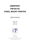
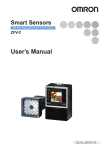
ZFV-C controllers have a function for communicating with external devices. Use this
function to read the data in ZFV-C controllers from the host and to write the setting data.
Communication is achieved via the Command and Response Method based on
CompoWay/F, OMRON's proprietary communication protocol. Controllers execute
processing according to the command sent from the host, and then return the result as a
response to the host that sent the command.
Host
ZFV-C controller (RUN mode)
Programmable Controller
Personal Computer
The command is entered.
The command is
executed.
During command
execution,
the controller is in a
non-measurement
state.
The result of command
execution is received.
1-2
ZFV-C
CompoWay/F Communication Command Reference
The execution result
is output.
Section 1
Setting the Communication Specifications
Setting the Communication Specifications
Section 1 About Communication Commands
Change the settings of the controller communication specifications for communicating with
the external device by CompoWay/F protocol.
Use a USB cable or RS-232C cable to connect ZFV-C controllers to external devices.
For the USB cable connection, download and install the USB driver beforehand.
For the USB driver, please contact your OMRON representative.
1.
Switch the controller to [MENU].
2.
Select [System2] - [Communication] to set the appropriate communication
specifications for the external device.
3.
Switch the controller to [RUN]. (This executes the save.)
ZFV-C
CompoWay/F Communication Command Reference
1-3
Section 1
Command Formats
Command Formats
Section 1 About Communication Commands
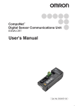
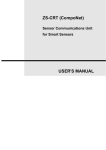
The command format of the communication commands is shown below.
In the following section, numerical values appended with "Hex" (e.g. 02Hex) indicate
hexadecimal numbers. Those annotated by " " or only numeral values indicate ASCII
characters.
(Text)
STX
Node No.
02Hex
(x 101) (x 100)
fixed
1 byte
2 bytes
Subaddress
SID
"00"
fixed
"0"
fixed
2 bytes
1 byte
Command text
MRC
BCC
03Hex
fixed
1 byte
1 byte
BCC calculating range
* In the example format, 1 byte = 1 ASCII character.
Element
1-4
SRC
ETX
Description
STX
This code indicates the start of a communication frame (02Hex).
Be sure to set the first byte to 02Hex.
When a controller receives STX while receiving a command, it receives the
command again starting from where it received STX.
Node No.
This is the node No. for identifying the destination. It should be fixed to "00."
* About node No.
This node No. indicates the connection group No. as seen from the host
device (PLC). Not only ZFV-C but also two or more devices can be
connected to the programmable controller. The No. assigned to devices
connected to a PLC such as this is referred to as a node No.
Subaddress
This should be fixed to "00."
SID (service ID)
This should be fixed to "0."
Command text
This is the text section of the command.
"Section 2 - Details of Commands" describes these sections by each individual
command.
ETX
This code indicates the end of the text (03Hex).
BCC
This is the block check character.
The exclusive OR (XOR) of values from node No. to ETX per single byte is
BCC.
ZFV-C
CompoWay/F Communication Command Reference
Section 1
Command Formats
■ Example of BCC calculation
STX
Node No.
Subaddress
SID
Command text
"00"
(3030Hex)
"0"
(30Hex)
"30053001"
(3330303533303031Hex)
ETX
BCC
Section 1 About Communication Commands
"0"
"0"
02Hex (30Hex)(30Hex)
03Hex 37Hex
Set the result of calculation, "37Hex," to the BCC section.
<Calculation>
BCC=30Hex+30Hex+30Hex+30Hex+30Hex+33Hex+30Hex+30Hex+35Hex+33Hex+
30Hex+30Hex+31Hex+03Hex=37Hex
"+" indicates the exclusive OR (XOR) operation.
ZFV-C
CompoWay/F Communication Command Reference
1-5
Section 1
Response Formats
Response Formats
Section 1 About Communication Commands
The response format of the communication commands is shown below.
In the following section, numerical values appended with "Hex" (e.g. 02Hex) indicate
hexadecimal numbers. Those annotated by " " or only numeral values indicate ASCII
characters.
STX
Node No.
02Hex
1
0
fixed (x 10 ) (x 10 )
1 byte
2 bytes
Subaddress
End code
"00"
fixed
MRC
2 bytes
ETX
BCC
03Hex
fixed
1 byte
1 byte
Description
Command Format, page 1-4
Node No.
Subaddress
End code
Refer to the next page.
Command text
This is the response text section of the command.
"Section 2 - Details of Commands" describes these sections by each individual
command.
ETX
Command Format, page 1-4
BCC
1-6
SRC
2 bytes
Element
STX
Response text
ZFV-C
CompoWay/F Communication Command Reference
Section 1
Response Formats
End codes of responses are shown below.
End code
Name
"00"
Normal end
Description
"0F"
Command error
"10"
Parity error
"11"
Framing error
A framing error occurred on one of the characters during command
reception.
"12"
Overrun error
An overrun error occurred on one of the characters during command
reception.
"13"
BCC error
"14"
Format error
"16"
Subaddress error
• The subaddress of the receive frame is illegal (not supported).
• No subaddress, SID, and command text exist.
• The subaddress is shorter than two characters, and no SID and
command texts exist.
"18"
Frame length error
The receive frame exceeds the specified (supported) number of
bytes.
Section 1 About Communication Commands
Command execution ended successfully.
The specified command could not be executed.
For details on non-execution, refer to the response code.
A parity error occurred on one of the characters during command
reception.
An illegal BCC was received.
• This response is returned when characters other than 0 to 9 or A to
F are used in command text sections. (except during echo back
tests)
• No SID and command text exist.
Or, no command text exists.
• Either MRC or SRC is missing in the command text.
An end code is returned after receiving one complete command frame addressed to the
node.
No response is made when ETX or BCC characters are missing from the command frame.
Noise may cause response errors or no response. Be sure to retry from the host.
It may take three seconds at longest from sending a command to receiving a response. If no
response is returned, be sure to send another command after waiting for at least three seconds.
ZFV-C
CompoWay/F Communication Command Reference
1-7
Section 1
Examples of Abnormal End
Examples of Abnormal End
Section 1 About Communication Commands
This section shows examples of end codes for abnormal ends that occur for received
commands.
● Invalid subaddress, and no SID and command text exist
Command
STX
Node No.
02Hex
Subaddress
"0"
"A"
ETX
BCC
03Hex
Response
STX
Node No.
02Hex
Subaddress
End code
"0"
"1"
"A"
"6"
ETX
BCC
03Hex
The end code is "16" (subaddress error).
• This response occurred because a subaddress was received and subaddress errors
have higher priority than format errors.
● No command text exists in the command
Command
STX
Node No.
02Hex
Subaddress
SID
ETX
"0"
"0"
03Hex
"0"
BCC
Response
STX
Node No.
02Hex
Subaddress
End code
"0"
"1"
"0"
"4"
ETX
BCC
03Hex
The end code is "14" (format error).
● Node No. is missing
Command
STX
ETX
02Hex
03Hex
BCC
One character is missing in the node No.
Response
No response is returned.
● No subaddress exists, and an invalid BCC is used
Command
STX
Node No.
02Hex
ETX
BCC
03Hex
Err
Response
STX
02Hex
Node No.
Subaddress
End code
"0"
"1"
"0"
"3"
ETX
BCC
03Hex
The subaddress is "00" and the end code is "13" (BCC error).
1-8
ZFV-C
CompoWay/F Communication Command Reference
Section 2
Details of Commands
2-2
Reading Parameter Areas
2-3
List of Parameter Area Read Commands
2-3
Commands and Responses
2-4
Writing Parameter Areas
Section 2 Details of Commands
About General Information of Communication
Commands
2-6
List of Parameter Area Writing Commands
2-6
Commands and Responses
2-7
Reading Controller Information
2-9
Operation Instructions
2-10
List of Operation Instruction Commands
2-10
Commands and Responses
2-10
ZFV-C
CompoWay/F Communication Command Reference
2-1
Section 2
About General Information of Communication Commands
About General Information of Communication Commands
Communication commands are categorized into the groups and meanings shown in the
following table:
Group
Meaning
Pages for Reference
Section 2 Details of Commands
Reading of parameter areas
Reading of setting values or measurement results
on the target channel
For measurement-related parameters, data is read
by specifying unit No. and data No.
p.2-3
(For details on unit
No. and data No.,
refer to Section 3.)
Writing of parameter areas
Writing of setting values or measurement results on
the target channel
For measurement-related parameters, data is
written by specifying unit No. and data No.
p.2-6
(For details on unit
No. and data No.,
refer to Section 3.)
Reading of controller information
Reading of information on models connected by
cable
p.2-9
Operation instructions
Data operations are executed on individual or all
banks.
p.2-10
[Notes on communication data transactions]
•The number of elements indicates the size of data to be exchanged. The ASCII
character length per element is determined according to parameter type code.
Specifically, this means
8000h to BFFFh: 4 characters per element
C000h onwards: 8 characters per element
The Number of elements is "1" for all commands in this manual. Therefore, enter
"8001h" to specify the number of elements.
•Machine No. indicates the channel No. of the destination controller.
•All data is exchanged using hexadecimal numbers. Therefore, "15" in decimal
annotation, for example, should be expressed as "0000000Eh." (*1)
•Negative values are expressed as 2's complement. For example, "-100" should be
expressed as "FFFFFF9Ch." (*1)
•When measured values are abnormal values, the data section is expressed as
"7FFFFFFXh" ("X" varies depending on the case). (*1)
*1: This is an example of eight characters per element.
2-2
ZFV-C
CompoWay/F Communication Command Reference
Section 2
Reading Parameter Areas
Reading Parameter Areas
The following describes reading of parameter areas.
List of Parameter Area Read Commands
MRC SRC
Parameter
type
Specification
of number of
elements
Read start
address
Data to be read
Section 2 Details of Commands
Data name
Data
length
*1
Current bank
No.
02h
01h
8000h
<Machine No.>
8001h
Bank No.
16
Reading
processing
unit data
02h
01h
C000h+
<Parameter
No.>
XXYYh
(XX: <unit No.>,
YY: <machine
No.>)
8001h
Data to be read
32
*1 This refers to the ASCII character length. For details, refer to p.2-2.
For details on the unit No. and parameter No. of each processing unit, refer to "Section 3
- Unit Nos. and Parameter Nos."
Example 1: To read the current bank No. from a 2CH controller, assign a command as follows:
[Machine No.]=0002h
MRC
02h
SRC
01h
Parameter type
8000h
Read start address
0002h
Number of
elements
8001h
Example 2: To read the judgment result from a 1CH controller, assign a command as follows:
[Data No.]=00h, [Unit No.]=02h, [Machine No.]=0001h
MRC
02h
SRC
01h
Parameter type
C000h
Read start address
0201h
Number of
elements
8001h
ZFV-C
CompoWay/F Communication Command Reference
2-3
Section 2
Reading Parameter Areas
Commands and Responses
● Command
Section 2 Details of Commands
2-4
MRC
SRC
"02"
"01"
2 bytes
2 bytes
Parameter type
Read start address
Number of elements
4 bytes
4 bytes
4 bytes
Element
Parameter type
Description
Specify parameters corresponding to the data to be acquired.
List of Parameter Area Read Commands, p.2-3
Read start address
Specify the machine No. (i.e. CH No.) of the controller to read data from by
using an ASCII code expressed in hexadecimal.
Note that the format in the case of a "processing unit data read" command is
XXYYh (where, XX: unit No., YY: machine No.)
Unit Nos. and Parameter Nos., p.3-1
Number of elements
Specify the number of elements corresponding to the parameter type.
List of Parameter Area Read Commands, p.2-3
ZFV-C
CompoWay/F Communication Command Reference
Section 2
Reading Parameter Areas
● Response
MRC
SRC
"02"
"01"
2 bytes
2 bytes
Response code
Parameter type
Read start address
4 bytes
4 bytes
4 bytes
Data to be read
4 bytes
Requested data
(depending on command)
Element
Section 2 Details of Commands
Number of elements
Description
Response code
Indicates the controller status for the command. Data to be read is not returned
when an error occurs.
Data to be read
Data to be read is expressed by using an ASCII code annotated in
hexadecimal.
The data length varies depending on commands.
List of Parameter Area Read Commands, p.2-3
Response code for a normal end
Response code
Response code
Name
Normal end
Description
No errors occurred.
Response codes when an error occurs
Response code
Error name
Cause
"1001"
Long command length
The command is too long.
"1002"
Short command length
The command is too short.
"1003"
Inconsistent number of
elements/data
The number of elements and data do not match.
"1101"
Area type error
The parameter type is wrong.
"1103"
Start address outside of
range error
The read start address is out of range.
The read start address specifies the sensor of the
unconnected Machine No.
The bit position is other than "00."
"1104"
End address outside of
range error
The specified number of elements is out of range.
"2203"
Operating error
This is a read error.
"2204"
Operating error
The sensor's operating mode is other than RUN.
"2205"
Operating error
This is an invalid command.
ZFV-C
CompoWay/F Communication Command Reference
2-5
Section 2
Writing Parameter Areas
Writing Parameter Areas
The following describes writing of parameter areas.
List of Parameter Area Writing Commands
Section 2 Details of Commands
Parameter
type
Write start
address
Specification
of number of
elements
Data name
MRC SRC
Bank
switching
02h
02h
8000h
<Machine No.>
8001h
Writing
processing
unit data
02h
02h
C000h+
<Parameter
No.>
XXYYh
(XX: <unit No.>,
YY: <machine
No.>)
8000h +
Data to be written
<Number of
elements>
Data
length
*1
Data to be written
bank No. (1 to 8)
16
32
*1 This refers to the ASCII character length. For details, refer to p.2-2.
For details on the unit No. and parameter No. of each processing unit, refer to "Section 3
- Unit Nos. and Parameter Nos."
Example 1: To switch the bank of a 2CH controller to "2", assign a command as follows:
[Machine No.]=0002h, [Data to be written]=0002h
MRC
02h
SRC
02h
Parameter type
8000h
Read start address
0002h
Number of
elements
8001h
Data to be
written
0002h
Example 2: To set the threshold value of a 1CH controller (ITEM=match), assign a command as follows:
[Data No.]=28h, [Unit No.]=02h, [Machine No.]=01h, [Data to be written]=00000050h
MRC
02h
2-6
ZFV-C
SRC
02h
Parameter type
C028h
CompoWay/F Communication Command Reference
Read start address
0201h
Number of
elements
8001h
Data to be
written
00000050h
Section 2
Writing Parameter Areas
Commands and Responses
● Command
SRC
"02"
"02"
2 bytes
2 bytes
Number of elements
Parameter type
Write start address
4 bytes
4 bytes
Section 2 Details of Commands
MRC
Data to be written
"8001"
4 bytes
Element
Parameter type
4 bytes
Description
Specify parameters corresponding to the data to be written.
List of Parameter Area Write Commands, p.2-6
Write start address
Specify the machine No. (=CH No.) of the controller to write data to using an
ASCII code expressed in hexadecimal.
Note that the format in the case of a "processing unit data write" command is
XXYYh (where, XX: unit No., YY: machine No.)
Unit Nos. and Parameter Nos., p.3-1
Number of elements
Specify the number of elements corresponding to the parameter type.
List of Parameter Area Write Commands, p.2-6
Data to be written
Data to be written is specified by using an ASCII code expressed in hexadecimal.
The data length varies depending on commands.
• List of Parameter Area Write Commands, p.2-6
• Do not issue commands other than specified parameter
types. Issuing wrong commands may rewrite internal
parameters. If the internal parameters of connected
sensors are rewritten, execute the operation instruction
command "EEPROM initialization."
ZFV-C
CompoWay/F Communication Command Reference
2-7
Section 2
Writing Parameter Areas
● Response
MRC
SRC
"02"
"02"
2 bytes
2 bytes
Response code
4 bytes
Element
Section 2 Details of Commands
2-8
Response code
Description
Indicates controller status for the command.
Response code for a normal end
Response code
"0000"
Name
Normal end
Description
No errors.
Response codes when an error occurs
Response code
Error name
Cause
"1001"
Long command length
Command length is too long.
"1002"
Short command length
Command length is too short.
"1003"
Inconsistent number of
elements/data
Number of elements and data do not match.
"1100"
Parameter error
Data to be written is out of specified range.
"1101"
Area type error
Parameter type is wrong.
"1103"
Start address outside of
range error
Writing start address is out of range.
Writing start address specifies the sensor of the
unconnected Machine No.
"1104"
End address outside of
range error
Specified number of elements is other than "8001."
"2203"
Operating error
Setting is abnormal.
Refer to the User's Manual of the ZFV-C for setting
error conditions of thresholds and the hysteresis
width.
"2204"
Operating error
Operating mode of sensor is other than RUN.
"2205"
Operating error
Invalid command.
ZFV-C
CompoWay/F Communication Command Reference
Section 2
Reading Controller Information
Reading Controller Information
The following describes reading of ZFC-V model, for example.
● Command
SRC
"05"
"01"
2 bytes
2 bytes
Section 2 Details of Commands
MRC
● Response
MRC
SRC
"05"
"01"
2 bytes
2 bytes
Response code
Model
4 bytes
20 bytes
Element
Version
20 bytes
Description
Response code
Indicates the controller status for the command. Data to be read is not returned
when an error occurs.
Model
The model is expressed by 20 ASCII characters.
Version
The version is expressed by 20 ASCII characters.
Response code for a normal end
Response code
"0000"
Name
Normal end
Description
No errors occurred.
Response codes when an error occurs
Response code
Error name
Cause
"1001"
Long command length
The command is too long.
"1002"
Short command length
The command is too short.
ZFV-C
CompoWay/F Communication Command Reference
2-9
Section 2
Operation Instructions
Operation Instructions
The following describes execution of operation instructions that are issued to controllers.
List of Operation Instruction Commands
Section 2 Details of Commands
Instruction Name
MRC
SRC
Instruction
code
Related information
1
Related information 2
Initialization of controller
settings (Flash)
30h
05h
55h
<Machine No.>
Save controller settings
(Flash)
30h
05h
57h
<Machine No.>
Measurement execution
30h
05h
90h
<Machine No.>
Measurement method (one
shot measurement/continuous
measurement/end continuous
measurement=0/1/2)
Key lock status setting
30h
05h
CAh
<Machine No.>
Lock status
(0: unlocked 1: locked)
Clear password
30h
05h
CCh
<Machine No.>
0000h
Clear measurement
values
30h
05h
CDh
<Machine No.>
0000h
Complete INIT initializes all settings (settings of all banks and system settings).
Example: To execute Complete INIT of a 2CH controller, assign a command as follows:
[Related information 1]=02h
MRC
30h
SRC
05h
Instruction code
55h
Related information 1
02h
Related
information
2
0001h
Commands and Responses
● Command
MRC
SRC
"30"
"05"
2 bytes
2 bytes
Instruction
Related
code
information 1
2 bytes
2 bytes
Element
2-10
Related
information 2
4 bytes
Description
Instruction code
Specify commands corresponding to the instruction to be executed.
Related information 1
Specify the channel No. of the controller targeted by the command.
Example: In the case of 2CH, specify "02."
Related information 2
Normally, a setting other than "0000" is not accepted.
ZFV-C
CompoWay/F Communication Command Reference
Section 2
Operation Instructions
● Response
MRC
SRC
"30"
"05"
2 bytes
2 bytes
Response
code
4 bytes
Element
Instruction
Related
code
information 1
2 bytes
Related
information 2
2 bytes
4 bytes
Description
Indicates the controller status for the command.
Instruction code
A code the same as the transmitted code is returned.
Section 2 Details of Commands
Response code
Related information 1
Related information 2
Response code for a normal end
Response code
"0000"
Name
Normal end
Description
No errors occurred.
Response codes when an error occurs
Response code
Error name
Cause
"1001"
Long command length
The command is too long.
"1002"
Short command length
The command is too short.
"1101"
Area type error
The instruction code is wrong.
"1103"
Start address outside of range The related information specifies the sensor of an
error
unconnected machine No.
"2203"
Operating error
The setting is abnormal. For details on error conditions,
refer to the ZFV-C User's Manual.
"2204"
Operating error
The sensor's operating mode is other than RUN.
"2205"
Operating error
This is an invalid command.
ZFV-C
CompoWay/F Communication Command Reference
2-11
Section 2
Operation Instructions
Section 2 Details of Commands
2-12
ZFV-C
CompoWay/F Communication Command Reference
Section 3
Unit Nos. and Parameter Nos.
Parameter List (ZFV-C)
Section 3 Unit Nos. and Parameter Nos.
Setting Value Acquisition/Change Commands
3-2
3-2
ZFV-C
CompoWay/F Communication Command Reference
3-1
Section 3
Setting Value Acquisition/Change Commands
Setting Value Acquisition/Change Commands
■ Parameter List (ZFV-C)
"Common" parameters are common regardless of the currently selected item. Also, the
parameters under "common" parameters differ according to the currently selected item.
● Common
Section 3 Unit Nos. and Parameter Nos.
3-2
Unit No.
Data No.
Parameter
Setting range/output
range
00h
24h
Light brightness (left)
0 to 5
00h
25h
Light brightness (up)
0 to 5
00h
26h
Light brightness
(right)
0 to 5
00h
27h
Light brightness
(down)
0 to 5
Remarks
Read/write
● Search (SEARCH)/Match (MATCH)
Unit No.
02h
Data No.
0h
Parameter
Judgment
Setting range/output
range
-2: measurement off
-1: NG
0: OK
02h
01h
Measured value
0 to 100
02h
02h
Measurement result
maximum value
0 to 100
02h
03h
Measurement result
minimum value
0 to 100
02h
04h
Measurement result
average value
0 to 100
02h
14h
Measurement count
0 to 9999999
02h
15h
NG count
0 to 9999999
02h
16h
NG occurrence ratio
0 to 99.999
02h
28h
Threshold
0 to 100
ZFV-C
CompoWay/F Communication Command Reference
Remarks
Read only
Read/write
Section 3
Setting Value Acquisition/Change Commands
● Area 1 (AREA1)/Area 2 (AREA2)/Area 3 (AREA3)
Unit No.
Data No.
Parameter
Setting range/output range
02h
00h
Judgment
-2: measurement off
-1: NG
0: OK
02h
01h
02h
(Area 1/3)
04h
(Area 2)
0Ah
Measured value
Measurement result 0 to 999
maximum value
0 to 999
02h
(Area 1/3)
05h
(Area 2)
0Bh
Measurement result 0 to 999
minimum value
02h
(Area 1/3)
06h
(Area 2)
0Ch
Measurement result 0 to 999
average value
14h
Measurement count 0 to 9999999
02h
15h
NG count
0 to 9999999
02h
16h
Fault rate
0 to 99.999
02h
(Area 1/2)
24h
(Area 3)
27h
Upper limit value
0 to 999
02h
(Area 1/2)
25h
(Area 3)
28h
Lower limit value
0 to 999
Section 3 Unit Nos. and Parameter Nos.
02h
Remarks
Read only
Read/write
● Brightness (BRIGHT)
Unit No.
Data No.
Parameter
Setting range/output range
02h
00h
Judgment
-2: measurement off
-1: NG
0: OK
02h
01h
Measured value (average density)
0 to 255
02h
02h
Measured value (density deviation) 0 to 127
02h
03h
Measured result (average density)
maximum value
0 to 255
02h
04h
Measured result (average density)
minimum value
0 to 255
02h
05h
Measured result (average density)
average value
0 to 255
02h
06h
Measured result (density deviation) 0 to 127
maximum value
02h
07h
Measured result (density deviation) 0 to 127
minimum value
02h
08h
Measured result (density deviation) 0 to 127
average value
02h
14h
Measurement count
0 to 9999999
02h
15h
NG count
0 to 9999999
02h
16h
Fault rate
0 to 99.999
02h
25h
Average density upper limit value
0 to 255
02h
26h
Average density lower limit value
0 to 255
02h
27h
Density deviation upper limit value
0 to 127
02h
28h
Density deviation lower limit value
0 to 127
Remarks
Read only
Read/write
ZFV-C
CompoWay/F Communication Command Reference
3-3
Section 3
Setting Value Acquisition/Change Commands
● Color inspection (HUE)
Unit No.
02h
Section 3 Unit Nos. and Parameter Nos.
3-4
Data No.
00h
Parameter
Judgment
Setting range/output
range
-2: measurement off
-1: NG
0: OK
02h
01h
Measured value
0 to 509
02h
05h
Measurement result
maximum value
0 to 509
02h
06h
Measurement result
minimum value
0 to 509
02h
07h
Measurement result
average value
0 to 509
02h
14h
Measurement count
0 to 9999999
02h
15h
NG count
0 to 9999999
02h
16h
Fault rate
0 to 99.999
02h
27h
Threshold
0 to 509
Remarks
Read only
Read/write
● Width (WIDTH)
Unit No.
Data No.
Parameter
Setting range/output
range
02h
00h
Judgment
-2: measurement off
-1: NG
0: OK
02h
01h
Measured value
0 to 999
02h
02h
Measurement result
maximum value
0 to 999
02h
03h
Measurement result
minimum value
0 to 999
02h
04h
Measurement result
average value
0 to 999
02h
14h
Measurement count
0 to 9999999
02h
15h
NG count
0 to 9999999
02h
16h
Fault rate
0 to 99.999
02h
26h
Upper limit value
0 to 999
02h
27h
Lower limit value
0 to 999
ZFV-C
CompoWay/F Communication Command Reference
Remarks
Read only
Read/write
Section 3
Setting Value Acquisition/Change Commands
● Position (POSITION)
Unit No.
02h
Data No.
00h
Parameter
Judgment
Setting range/output
range
-2: measurement off
-1: NG
0: OK
01h
Measured value
0 to 468
02h
02h
Measurement result
maximum value
0 to 468
02h
03h
Measurement result
minimum value
0 to 468
02h
04h
Measurement result
average value
0 to 468
02h
14h
Measurement count
0 to 9999999
02h
15h
NG count
0 to 9999999
02h
16h
Fault rate
0 to 99.999
02h
26h
Threshold
0 to 468
Read only
Section 3 Unit Nos. and Parameter Nos.
02h
Remarks
Read/write
● Count (COUNT)
Unit No.
Data No.
Parameter
Setting range/output
range
02h
00h
Judgment
-2: measurement off
-1: NG
0: OK
02h
01h
Measured value
0 to 128
02h
02h
Measurement result
maximum value
0 to 128
02h
03h
Measurement result
minimum value
0 to 128
02h
04h
Measurement result
average value
0 to 128
02h
14h
Measurement count
0 to 9999999
02h
15h
NG count
0 to 9999999
02h
16h
Fault rate
0 to 99.999
02h
26h
Upper limit value
0 to 255
02h
27h
Lower limit value
0 to 255
Remarks
Read only
Read/write
ZFV-C
CompoWay/F Communication Command Reference
3-5
Section 3
Setting Value Acquisition/Change Commands
● Character (CHARA1)/Character (CHARA2)
Unit No.
Section 3 Unit Nos. and Parameter Nos.
3-6
Data No.
Parameter
Setting range/output
range
02h
00h
Judgment
-2: measurement off
-1: NG
0: OK
02h
01h
Measured value
(CHARA1) 0 to 127
(CHARA2) 0 to 100
02h
02h
Measurement result
maximum value
(CHARA1) 0 to 127
(CHARA2) 0 to 100
02h
03h
Measurement result
minimum value
(CHARA1) 0 to 127
(CHARA2) 0 to 100
02h
04h
Measurement result
average value
(CHARA1) 0 to 127
(CHARA2) 0 to 100
02h
14h
Measurement count
0 to 9999999
02h
15h
NG count
0 to 9999999
02h
16h
Fault rate
0 to 99.999
02h
(CHARA1)
26h
Threshold
0 to 100
02h
(CHARA2)
35h
Threshold
0 to 100
ZFV-C
CompoWay/F Communication Command Reference
Remarks
DATAGET compatible
DATASET/DATAGET
compatible
Revision History
Revision code
01
01A
Date
Revised contents
January 2006
Original production
May 2006
Function added as per software version upgrade (Ver1.30)
July 2007
Page 2-7: Response information added.
OMRON Corporation
Industrial Automation Company
Sensing Devices Division H.Q.
Application Sensors Division
Shiokoji Horikawa, Shimogyo-ku,
Kyoto, 600-8530 Japan
Tel: (81)75-344-7068/Fax: (81)75-344-7107
Regional Headquarters
OMRON EUROPE B.V.
Sensor Business Unit,
Carl-Benz-Str. 4, D-71154 Nufringen,
Germany
Tel: (49)7032-811-0/Fax: (49)7032-811-199
OMRON ELECTRONICS LLC
1 East Commerce Drive, Schaumburg, IL 60173
U.S.A.
Tel: (1)847-843-7900/Fax: (1)847-843-8568
OMRON ASIA PACIFIC PTE. LTD.
83 Clemenceau Avenue,
#11-01, UE Square,
239920 Singapore
Tel: (65)6835-3011/Fax: (65)6835-2711
OMRON (CHINA) CO., LTD.
Room 2211, Bank of China Tower,
200 Yin Cheng Road (M),
Shanghai, 200120 China
Tel: (86)21-5037-2222/Fax: (86)21-5037-2200
Authorized Distributor:
Cat. No. Z243-E1-01A
C
OMRON Corporation 2006
All Rights Reserved.
Note: In the interest of product improvement,
specifications are subject to change without notice.
Printed in Japan.
0705-0.2M(0705)(M)
0706-0.2M(0606)(M)0705-0.2M(0705)(M)