1
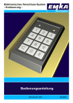
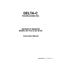
Biogas 08
Basissystem
Version 4
SETTING UP AND USER'S MANUAL
Gasanalyzer and Warning System
Setting up and user's manual
Biogas 08
Version 4
Table of contents
Page 2 of 24
Chapters
Pages
General informations
3
Application
3
Description of the product
3
Unity of measures
3
Assembly
4
Functionning
4
Technical datas
6
Connection
9
Display and commands
10
Programs
11
Initialization of the system
12
STAND-BY Mode
12
Measures
13
Parameters of the system
14
Datalogger
20
Vizualisation of the analysis
22
Conformity certificate of anti-detonation
23
Options
24
Guarantee
24
Setting up and user's manual
Biogas 08
Version 4
Important note
This setting up and users's manual is conceived for the standard version of
the GMC 08 Biogas08-Analyzer.
For options cases, please check the specific manuals of these options.
Application
A continuous surveillance of the produced biogas is necessary to efficiently
control the production process of a biogas plant.
Using a Bieler + Lang biogas analysis equipment the contents of methane,
carbon dioxide, residual oxygen and hydrogen sulphide are measured in
individually determined measuring cycles.
Thanks to its simple and compact conception, this equipment can be
kmodified and widened in its functions with reduced cost in a very quickly.
Products description
●
●
●
●
●
●
●
●
●
●
●
●
●
●
Unity of measures
Analysis of a gas produced from methanisation
Conceived for a regular and continuous analysis directly on the biogas
plant
Analysed component: CH4, H2S, CO2, O2
Technics of measurements: NDIR infrared sensor double beams for the CH 4 and
the CO2, electrochemical sensor for the H 2S und O 2
Pressure and temperature compensation of the infrared sensor
Flame arrester security following the current standard EN 12874
Ventilation integrated in the analyzer's case
Clear and easy to use
Data storage for measured values
Relay of the programmation of the process
Output of the results of each component in signal 4-20mA
Option: 2 gas detector for the machinery room's supervision
Option: preparation and cooling of the biogas to be analysed at 5°C
to dry it
Option: Up to 4 possible measurement points
Gas
Unity of measures
CH4
0 – 100 vol%
H2S
0 – 5.000 ppm
O2
0 – 25 vol%
CO2
0 – 40 vol%
Page 3 of 24
Setting up and user's manual
Biogas 08
Version 4
Assembling
The Analyzer GMC08 exists in 2 versions:
●with drying by cooling the sampling biogas
●without drying the sampled gas
All the components are integrated in a closed and pre-cabled case.
All the gas' connection necessary for the sampling are situated at the bottom
on the right of the housing. The electric connection are also placed under the
case. The visualisation screen und the control unit are integrated on the side
of the locker's door. The analyzer owns a integrated and automatic
ventilation for security reasons. The internal's components are separated in 2 zones.
On the right are fixed the pneumatic component with gas sensors/captors. On the
left are placed the electronical components and the different relay of commands.
BIOGAS08
Ch1
0
METHAN
MESSGAS 1
Ch2 0
KOHLENDIOXID
MESSGAS 2
Ch3 0
SAUERSTOFF
MESSGAS 3
Ch4 0
H2S
MESSGAS 4
Functioning
16.04.2008
16:13
100 VOL%
25.0
40 OL%
V
25 OL%
V
10.0
06.3
1000 PPM
0250
The Analyzer GMC08 owns 2 functioning modes.
In the automatic mode, the analysis are made by regular and programmed intervals.
Moreover the system can make separate and other intervals analysis.
In this mode, an analysis requested by manually operated control.
At each new sample, the "zero points" of the differents captors and sensors can be
adjusted thanks to surrounding filtered air.
This air is filtred thanks to particles filtres and coal filter, cleaned and sent
back by solenoid valves to the different sensors.
After the successful adjustment of the "zero point", the pump withdraws the biogas
to be analysed and conveys it through a flamm arrester to the explosion protection
until the gas' cooler.
The sampling gas is cooled down to a temperature of 5°C.
The produced condensate is then pumped and evacuated through the output
conceived for this effect (supple pipe to link at the output and evacuation of the
condensate to outside). The sensor H2S is protected by an automatic dilution
of the sampled gas. The biogas is then injected in the different captors to be analysed.
At the end of the measures, the network of the Analyzer's sampled gas is cleaned by
an automatic injection of air.
The measured values can be read during the development of the analysis on the
display unit. After the measurement, the system compares the results with the
alarm thresholds indices of each component recorded in the program.
These thresholds obtain in addition to the alarms attribut for the overtaking of the low
and for the higher indices.
Page 4 of 24
Setting up and user's manual
Biogas 08
Version 4
Functionning
Thanks to this programmation, the gas' concentration to be analysed can vary.
The system releases the alarm relay at each overtaking of these threshold. The
analyzer emits for each component a visual alarm by a signal 4-20mA. The
program records 1.440 analysis in its system. The results recorded are
readable thanks to an interface RS232. The 13 last analysis' results are
readable on the analyzer control screen.
.
.
In option, it is possible to plug in the analyzer 2 gas detectors for
the machinery room. These detector's alarms are linked to the equipment's
collective alarm's message. This evaluation of the threshold is realised
permanently.
The analyzer is easy to maintain and doesn't require a big maintenance. All
the sensors are easily accessible. For the review and adjustment of the gas
sensors is an additional connection available in the system
Page 5 of 24
Setting up and user's manual
Biogas 08
Version 4
Technical datas
Gas
Unities
Resolution
Technics
Unity of measures
CH4
0 – 100 vol%
0,1 vol%
NDIR infrared double beam
H2S
0 – 5.000 ppm
1 ppm
elektrochemical
Gas sensor
O2
0 – 25 vol%
0,1 vol%
elektrochemical
Gas sensor
CO2
0 – 40 vol%
0,1 vol%
NDIR infrared double beam
Interfaces
Electricity supply
Environment
Biogas input
Page 6 of 24
Display /
Measurements
160x160 Pixelilluminated graphic screen
Status of each component
Relay output
Digital output
2 alarm thresholds for each component
2 alarm thresholds for the collective alarm
Maintenance
Breakingdowns, errors
RS232, transfert and digital edition of the analysis
Similar output
output signal 4-20mA for each component
Similar input
2x 4-20 mA for the gas detectors in the
machinery room
Electricity supply
230 VAC, 50 Hz (85 - 264 VAC / 47 – 63 Hz)
Consumption
Standby: 0,2 A
ON: 0,7 A
Commutation
Relay's outputs
250 VAC, 2 A
Air temperature
+10°C – +40°C
Storage temperature
-10°C - +50°C
Humidity rate
< 80% rel. F.
Air pressure
850 – 1100 hPa
Gas connection
Sample gas, condensate: Id/Ad = 4/6 mm
Output diam. int/diam.ext = 9/12 mm
Safety
Device
Explosion protection with flame arrester
Sample gas
Input
IIG IIB3
PTB 04 ATEX 4003X
Biogas08 without cooler: max 5 °C
Biogas08 with cooler: max 40 °C
Biogas' temperature
max 40 °C
Input's pressure
-50 … +10 hPa
Output's pressure
the sampled biogas is to be re-thrown back outside without pressure
Setting up and user's manual
Biogas 08
Version 4
Technical datas
Case
Painted metallic case
Dimension
(WxHxD)
ca. 580 x 780 x 230
Weight
ca. 30 kg
Protection Factor
IP20
Case/Dimension
Page 7 of 24
Setting up and user's manual
Biogas 08
Version 4
Page 8 of 24
Setting up and user's manual
Biogas 08
Version 4
CONNECTIONS
NOTE
Assembling
Please imperatively respect the following instructions:
●manipulate the analyzer with caution during the transport and handling
●Works including: setting-up, putting into service, maintenance and mending
must be made by qualified employees
● Read the notice before setting-upand putting into service, respect without
restriction the security instruction which are described
●Protect
the analyzer from dust, water, oil, dirt or anything that could
damage it
●Setting up is allowed only outside ATEX zones
●Set-up in a dry place, with stable temperature and no vibrations
●Forsee enough space to access and do the system's maintenance
Important remarks
This user's and setting-up manual describes the caracterisitics and the use
of the Biogas GMC08 analyzer in its standard version. For options,
please refer to the specific manual attached for these options.
.
Electric
connection
See the plan "electric connection" attached.
GAS
connection
●
●
●
●
Biogas input
Connection for the biogas' injection to analyse
OUTPUT Biogas 1 / OUTPUT Biogas 2
Outputs towards the outside of the biogas', after analysis. The disposal
towards the outside must be made without pressure (as short as possible)
INPUT for calibration gas
Connection for the grading gas' injection during the trail period
OUTPUT condensate
Outputs towards the outside for the condensates' rejection.
Page 9 of 24
Setting up and user's manual
Biogas 08
Version 4
DISPLAY and
COMMAND
BIOGAS08
0
16.04.2008
16:13
100 VOL%
METHAN
MESSGAS 1
Ch2 0
40 VOL%
KOHLENDIOXID
MESSGAS 2
Ch3 0
25 VOL%
Ch1
SAUERSTOFF
MESSGAS 3
Ch4 0
H2S
MESSGAS 4
Ready
Bus actif
Switched on
flashing
44.0
01.0
2000 PPM
0250
Equipment
Communication established with the system
Pause/Wartung switched on
The analyzer is on pause (stand-by)
Err
switched on
A1
switched on
A2
switched on
Component's channel on, declares :
- computer problem
- electrical problem
- pneumatic problem
- Parameter of the measures outside tolerances
- Failure of the sensor's adjustmen
Channel of the switched on component:
Alarm threshold 1 activated
Channel of the switched on component:
Alarm threshold 2 activated
- One of the channel has activated the alarm
- Gas detector (option) has acitvated the alarm
Methane measures: failing / mistake
or threshold with overtaken alarms
Carbon dioxyde measures: failing / mistake or
threshold with overtaken alarms
Oxygen measures: failing / mistake or
threshold withe overtaken alarms
Hydrogen sulfide measures: failing / mistake
or threshold with overtaken alarms
Collective alarm LED Err, A1 oder A2
switched on
LED Err, A1 oder A2
Ch1 CH4
switched on
LED Err, A1 oder A2
Ch2 CO2
switched on
Ch3 O2
LED Err, A1 oder A2
switched on
LED Err, A1 oder A2
Ch4 H2S
switched on
Button
Turn
Press
Com
Page 10 of 24
55.0
- Navigate and change point in the menu
- modify the parameter of the datas
Record the executed modifications
Interface in serie
Setting up and user's manual
Biogas 08
Version 4
Presentationof the program
Initialisation of the system
OPTIONS
CALIBRATION MODE
MEASUREMENTS MODE
FUNCTIONING MODE
DATALOGGER
OPTIONS:
CHANNEL modification
DATE / TIME
LIGHTENING
CONTRAST
LED'S-TESTING
TENSIONS
VERSION of the software
EXIT
CALIBRATION MODE:
CALIBRATION
ADJUSTMENT
SENSOR'S sensitivity
EXIT
MEASUREMENTS MODE:
SAMPLING POINTS
MEASURES INTERVALS
ALARM FACTORS
EXTERNAL PROBE
EXIT
FUNCTIONING MODE:
AUTO/MANUAL
ALARM/RESET
EXIT
DATALOGGER:
OUTPUT ON RS232
OUTPUT ON DISPLAY
SUPPRESSION RESULTS
EXIT
Page 11 of 24
Setting up and user's manual
Biogas 08
Version 4
INITIALISATION
of the system
The system initializes itself automatically as soon as its starts. The following
functions are made one after another
.Hinweis: Abhängig von den eingestellten Parametern, kann dieser Vorgang
bis zu sieben Minuten dauern.
●
●
●
●
●
STARTING THE COMMAND'S PLATES
- Initialization and control of the command's plates
STARTING THE MEASUREMENTS SYSTEM
- Adjustement of the different sensors and parameters
TEST TO CONTROL THE SYSTEM OF ANALYSIS
- Control of the sensor's sensitivity and data's measures
TEST TO CONTROL THE GAS COOLER
- turn the gas cooler on (if chosen option) and wait until the temperature
allready recorded is reached.
ADJUSTMENT (prepared in the factory)
-Aspiration of the calibration gas
-Starting up the calibration at the "zero point"
-Calibration in due course
-Test to control the calibration
- Adjustment of the "zero points" of each component
- Adjustement and reinforcement of the O2 sensor (Display 20,9 vol%)
After a successful initialization, the system puts itself on "stand-by" mode.
STAND-BY
Mode
The analyzer procedes to automatic or manual measures. During the pause
between the analysis, the display on the screen is the following:
BIOGAS08
16.04.2008
16:13
STAND-BY
ANALYSIS MODE: AUTO
IN 0005 MINUTES
MEASURES GAS POINT 01
or
BIOGAS08
16.04.2008
16:13
STAND-BY
ANALYSIS MODE: MANUAL
Measures with pressure
-- START/RESET -●
●
Page 12 of 24
AUTOMATIC MODE
The analysis are made automatically in defined intervals. The remaining
time until the next measure is displayed in minutes on the screen.
MANUAL MODE
Press the button START/RESET to launch a sampling
Setting up and user's manual
Biogas 08
Version 4
ANALYSIS
The analyzer GMC08 makes biogas samples following the programmed
cycles (Mode AUTO) or manually. Before each analysis, the grading "zero point" and
reinforcement of the signal of the oxygen's sensor are adjusted.
During the analysis, the datas are visible on the equipment's display. Then the results
are compared to the programmed threshold's alarms
The signals in 4-20mA show the state of each component until the next analysis
(Err, A1, A2 or nothing if ok).
After the alarm's reports, the GMC08 puts itself in "stand-by" mode.
The measurementsare visible later on the equipment's display via the
DATALOGGER or the interface RS232.
BIOGAS08
Ch1
0
16.04.2008
16:13
100 VOL%
55.0
METHANE
GAS MEASURE 1
Ch2 0
40 VOL%
CARBON DIOXYDE
GAS MEASURE2
Ch3 0
25 VOL%
OXYGEN
GAS MEASURE 3
Ch4 0
H2S
GAS MEASURE 4
44.0
01.0
2000 PPM
0250
Page 13 of 24
BSetting up and user's manual
Biogas 08
Version 4
System parameters
MAIN MENU
During the stand-by mode, all the parameters of the GMC08 Analyzer can be
modified. The main menu activates itself by pressing the big button on the
front of the case.
--> OPTIONS
CALIBRATION MODE
MEASUREMENTS MODE
FUNCTIONING
DATALOGGER
EXIT
●
●
●
●
●
●
OPTIONS
- General characterisitics of the system
CALIBRATION MODE
- Implementation of the calibration with a testing gas
MEASUREMENTS MODE
- Recording of the datas for the gas' analysis
FUNCTIONING
- Choose the automatic or a manual mode
- Alarmreset / Cancellation
DATALOGGER
- Visualisation and transfer of the results of the analysis
EXIT
- back to stand-by mode
OPTIONS
OPTIONS:
--> Channel modification
DATE / TIME
LIGHTENING
CONTRAST
LED'S-TESTING
TENSIONS
VERSION of the software
EXIT
CHANNEL MODIFICATION
CHANNEL modification:
--> Ch1.CH4:
--> ON
ON
Ch2.CO2:
ON
Ch3.O2:
AFF
Ch4.H2S:
EXIT
The analyzer GMC08 can analyse until 4 components. Choose the desired
components and modify the status of every on ON or OFF.
DATE / TIME
DATE / TIME:
--> DAY:
DATE:
MONTH:
YEAR:
HOUR:
MINUTES:
EXIT
--> Monday
16
04
2008
16
43
Modify the current date and time.
Page 14 of 24
Setting up and user's manual
Biogas 08
Version 4
System parameters
OPTIONS
LIGHTENING
LIGHTENING:
-->
0
100%
EXIT
Adjust the screen's luminosity.
CONTRAST
CONTRAST:
-->
0
100%
EXIT
Adjust the screen's contrast.
LED-TESTING
LED-TESTING:
--> LED:
--> ON
EXIT
To test the LED'S good working order.
TENSIONS
TENSIONS:
VDD.A:
VBAT.A:
VDD.S:
VBAT.S:
03.26
03.19
03.32
00.00
--> EXIT
Display of the internal tension to control.
Hinweis: Zur Pufferung der integrierten Echtzeituhr gegen Stromausfall ist
eine Batterie eingebaut. Die aktuelle Spannung wird durch den Wert VBAT.A
dargestellt. VBAT.A muss größer 02.50 sein. Die erwartete Lebensdauer
beträgt 36 Monate.
SOFTWARE VERSIONS
SOFTWARE VERSIONS:
DISPLAY:
COMMAND:
ANALYSIS:
04.3
04.3
0B.8
--> EXIT
Display the versions of the set-up programs.
Page 15 of 24
Setting up and user's manual
Biogas 08
Version 4
System parameters
CALIBRATION MODE
CALIBRATION MODE:
--> CALIBRATION
ADJUSTMENT
SENSOR'S-SENSITIVITY
EXIT
Regularly, a control of the sensitivity and of the good working order of the
different components'sensors, must be made. It is realised by injection a
grading gas:
●CALIBRATION
Comparaison of the results of a known testing gas
●ADJUSTMENT
Comparaison of the precision of the sensors with a concentration of
a known testing gas.
●SENSOR'S SENSITIVITY
Display of the sensitivity / precision of the different sensors.
CALIBRATION
CALIBRATION START:
--> START
EXIT
Procedure:
1) Connect the grading gas to the input "CALGAS" made for this purpose
2) Star the calibration
3) Automatic "back to zero"
4) During the display "Calgas aufgeben" and the measured datas, adjust
the calibration gas output at 60l./h.
5) After a successful procedure, automatic return to the main menu.
ADJUSTMENT
ADJUSTMENT:
--> TYPE OF GAS
CONCENTRATION
START
EXIT
●
●
●
ADJUSTMENT (TYPE OF GAS)
TYPE OF GAS:
Record the component of the used calibration gas
CONCENTRATION:
Record the concentration of each component
START:
Start the adjustment
TYPE OF GAS:
--> Ch1.CH4:
Ch2.CO2:
Ch3.O2:
Ch4.H2S:
EXIT
--> YES
YES
NO
YES
Define the type of gas (here Biogas) and its different components to be
analysed. For a gas like the biogas , give a channel for each component
and record it in mode YES.
NOTE: Ch3.O2 should be set to (NO), because before each measurement,
an automatic adjustment takes place.
Page 16 of 24
Setting up and user's manual
Biogas 08
Version 4
System parameters
CALIBRATION MODE
ADJUSTMENT (CONCENTRATION)
CONCENTRATION GAS:
--> Ch1.CH4: 60.00 VOL%
Ch2.CO2: 40.00 VOL%
Ch3.O2:
Ch4.H2S: 0300 PPM
EXIT
Record the concentration of the grading gas.
ADJUSTMENT (START)
ADJUSTMENT START:
--> START
EXIT
Procedure:
1) Connect the biogas to be analysed to the input made for this purpose
on the right under the case
2) Start the adjustment
3) Automatic "back to zero" before each adjustment
4) During the display "calgas aufgeben", adjust the gas debit to 60l./h
5) After a successful adjustment, automatic return to the main menu.
Page 17 of 24
Setting up and user's manual
Biogas 08
Version 4
System parameters
MEASUREMENT MODE
SAMPLING POINTS
ANALYSIS MODE:
--> SAMPLING POINTS
INTERVALS
ALARMS THRESHOLDS
EXT. PROBE
EXIT
EXT. SAMPLING POINTS:
--> Sampling point: 01
EXIT
It is possibility to connect until 4 different sampling points on the GMC08
Analyzer. Record here the number of sampling point.
.
MEASURING INTERVALS
MEASURING INTERVALS:
30 MIN
--> CURRENT:
HOUR OF REF: 12:00h
DIVIDER H2S : 01
Aspirat. Length1: 10 SEC
Aspirat. Length2:
Aspirat. Length3:
Aspirat. Length4:
EXIT
●CURRENT:
Define here the wished intervals between the sampling
OF REFERENCE:
The interval starts again each day at the define hour. Like that the intervals
between the analysis always stays synchronized even if there is a power
cut.
●DIVIDER H2S:
The sensor H2S is subject to wear. To extend its life span, there is a
possibility to reduce the number of analysis of this sensor:
Teiler 1: Analysis at each sampling as recorded in "current".
Teiler 2: Anaylisis of the H2S every 2 samples (here for example every
60 minutes)
●
ASPIRATION LENGTH
The required length for a secured transfer of the biogas from the sampling
point to the analyzer.
●HOUR
ALARM FACTORS
ALARM FACTORS:
--> Ch1.CH4: < 40.00 VOL%
Ch1.CH4: > 80.00 VOL%
Ch2.CO2: < 20.00 VOL%
Ch2.CO2: > 40.00 VOL%
Ch3.O2: < 02.00 VOL%
Ch3.O2: > 05.00 VOL%
Ch4.H2S: > 0500 PPM
Ch4.H2S: > 0700 PPM
EXIT
Alarm threshold 1
Alarm threshold 2
Alarm threshold 1
Alarm threshold 2
Alarm threshold 1
Alarm threshold 2
Alarm threshold 1
Alarm threshold 2
Record for each component and channel the alarm factor:
●
Symbol <
Alarm if overtaking of the minimum threshold recorded
●
Symbol >
Alarm if overtaking of the maximum threshold recorded
Page 18 of 24
Setting up and user's manual
Biogas 08
Version 4
System parameters
Measurements Mode
EXTERNAL PROBE
EXT. PROBE:
--> ext. PROBE 1
ext. PROBE 2
EXIT
PROBE 1 (2)
--> CURRENT:
UNITY:
MAX.:
ALARM 1:
ALARM 2:
EXIT
--> ON
%UEG
0100
0020
0040
Possibility to connect, in option, 2 gas detectors in the machinery room:
.
CURRENT
ON/OFF of the dectectors
●UNITY OF MEASURES
Unity: %UEG, PPM, VOL%
●MAXIMAL RATE
Display at 20mA external probe signal
●
ALARM 1 / ALARM 2
Release of the alarm in case the threshold is overtaken.
These alarms are recorded in output by a collective alarm.
●
System parameters
BETRIEBSMODUS:
- -> AUTO/MANUAL
ALARM/RESET
EXIT
AUTO / MANUAL
AUTO/MANUAL:
--> CURRENT: --> AUTO
EXIT
FUNCTIONING
Choose the desired functioning mode: automatic analysis (AUTO) or
occasionnal analysis (MANUAL).
ALARM / RESET
ALARM/RESET:
--> YES
EXIT
Cancellation of the alarms with "YES".
Page 19 of 24
Setting up and user's manual
Biogas 08
Version 4
System parameters
DATALOGGER
DATALOGGER:
--> OUTPUT RS232
OUTPUT ON SCREEN
SUPPRESSION RESULTS
EXIT
The 1.440 last analysis are recorded in the datalogger (memory) of the equipment
(30 days if the interval of sampling every 30 minutes)
OUTPUT LCD
DATALOGGER:
--> 16.04.2008 17:00 o'clock
16.04.2008 17:30 o'clock
16.04.2008 18:00 o'clock
EXIT
DATALOGGER:
16.04.2008 17:00
Ch1.CH4: 40.00 VOL%
Ch2.CO2: 20.00 VOL%
Ch3.O2:
00200 VOL%
Ch4.H2S: 0500 PPM
--> EXIT
The last 15 measurements can look on the equipment's display.
SUPPRESSION
SUPPRESSION:
--> Yes
EXIT
Suppress with "Yes" every result recorded in the GMC08's memory.
OUTPUT RS232
OUTPUT RS232:
--> START
EXIT
The recorded measurements can be read by the RS232's interface, choose
the parameters 8N1 under 9600 Baud.
Connect your computer with the USB wire (option) to the analyzer. During the
first data transfer, the system will ask for the installation of the programm
(included in the Analyzer's programm).
Start a Terminalemulator (z. B. PuTTY).
NOTE:
PuTTY ist a free Terminalemulator
.
In the connection choice, choose the option "SERIAL". In "Speed", choose
9600 Baud for the speed of data transfer and in "serial line", the number of the
serial interface.
Page 20 of 24
Setting up and user's manual
Biogas 08
Version 4
System parameters
DATALOGGER
Output RS232
Select a destination for the results' downloading.
Hinweis: Verwenden Sie „.csv“ als Dateiendung.
Start the terminal with "Open".
OUTPUT RS232:
--> START
EXIT
Start the downloading of the analysis by pressing on "START".
In the computer's window, you can follow the progress of the transfer. After
the downloading close the program and the "terminulator".
Page 21 of 24
Setting up and user's manual
Biogas 08
Version 4
Data processing
The downloaded results can be read and worked on by all programms,
like for example in a pivot table.
To do so, open your file withe the desired programm.
FIf the file doesn't appear as a choice, choose the type of file
(*.*)
Choose "semikolon" for the separation option on the "text import".
Page 22 of 24
Setting up and user's manual
Biogas 08
Version 4
Certificate of explosion protection with flame arrester
Detonationsicherung
Page 23 of 24
Setting up and user's manual
Biogas 08
Version 4
Accessories
●
●
●
●
Calibration gas
USB-cable to transfer and reading of the datalogger
Gas detector Type Exdetector HC100
Gas detector Type Exdetector HC200
Gas detector Type Gasmonitor HC150
Guarantee
Bieler + Lang GmbH
Gasmess- und Warnsysteme
Représentant en France:
Biomégan Energies SAS, Les Graves, 46140 CAILLAC
Telefon
Telefax
E-Mail
+33 (0) 5 65 23 45 24
+33 (0) 9 63 03 72 64
[email protected]
Internet
www.bieler-lang.de
Page 24 of 24
Technischer Stand: 08/2009
Technische Änderungen vorbehalten!