1
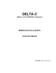
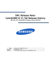
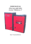
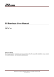
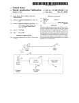
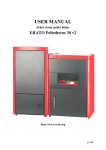
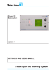
DELTA-C TECHNOLOGIES INC. WATERCUT MONITOR MODEL DC-1510 & DC-3510F Instruction Manual Issue date: July 7, 2008, Rev 2.4 Created Preliminary issue Released Rev 1.0 Rev 2.0 Rev 2.1 Rev 2.2 Rev 2.3 Rev 2.4 June 2, 2003 August 6, 2003 August 12, 2003 September 24, 2004 October 22, 2004 August 23, 2005 August 28, 2006 March 12, 2007 July 7, 2008 Delta-C Technologies Inc. Enderby, BC, Canada V0E 1V0 www.gasanalyzer.cn [email protected] ©2004, Delta-C Technologies Inc. - ii - TABLE OF CONTENTS 1.0 INTRODUCTION.....................................................................................................................1 1.1 MULTI CURVE OPERATION 1 1.2 UPDATING THE PROGRAM 2 Password protection..........................................................................................................................2 Changing the password.....................................................................................................................2 2.0 ASSEMBLY AND INSTALLATION..........................................................................................5 2.1 SENSOR ASSEMBLY, MODEL DC-1510 ONLY 5 Figure 1 Thermowell hole alignment to case...................................................................................6 2.2 ANALYZER INSTALLATION 6 Mechanical Installation.....................................................................................................................6 Electrical Installation .......................................................................................................................7 3.0 CALIBRATION THEORY........................................................................................................9 3.1MULTIPLE CALIBRATION METHODS 9 3.2BASIC THEORY 9 Figure 2 Ratio vs. water content...................................................................................................10 Figure 3 Ratio vs. water content and temperature.........................................................................11 4.0 CALIBRATION......................................................................................................................13 4.1 OPERATOR INTERFACE 13 4.2 CALIBRATION 14 Temperature Compensation............................................................................................................14 CS - Calibrate Simple.....................................................................................................................15 CF - Calibrate Full..........................................................................................................................16 CC - Calibrate Temp Compensation...............................................................................................17 CN - Calibrate Narrow....................................................................................................................18 CW - Calibrate Wide.......................................................................................................................19 CO - Calibrate Analog Output........................................................................................................20 CD - Calibrate Density....................................................................................................................21 ........................................................................................................................................................23 SA - Set Alarm................................................................................................................................23 SB - Set BS&W Averaging.............................................................................................................24 SO - Set Output Averaging.............................................................................................................24 ST - Set Temperature Averaging.....................................................................................................24 SD - Set Density Averaging............................................................................................................24 SU - Set Units.................................................................................................................................24 SV - Set Temperature Units............................................................................................................24 SC - Select curve.............................................................................................................................25 ........................................................................................................................................................25 DB - Display Water Content ..........................................................................................................25 DC - Display/Modify Calibration...................................................................................................26 .......................................................................................................................................................26 DI - Display Information................................................................................................................26 5.0 MODBUS INTERFACE.........................................................................................................29 5.1GENERAL 29 - iii - ©2004, Delta-C Technologies Inc. 5.2COMMUNICATION SETTINGS 29 5.3MASTER SETTING, TIMEOUT 29 5.4MODBUS CONFIGURATION 29 5.5 MODBUS ADDRESS ASSIGNMENTS 31 5.6 HYPERTERMINAL SETUP 32 6.0APPENDICES........................................................................................................................35 6.1 SPECIFICATIONS 35 General............................................................................................................................................35 Mechanical......................................................................................................................................35 Electrical.........................................................................................................................................35 Output.............................................................................................................................................35 TERMINAL/COMPUTER INTERFACE.......................................................................................35 6.2 DIAGRAMS 36 Figure 4 Terminal Wiring..............................................................................................................36 Figure 5 DC-1510 Dimensions.....................................................................................................37 Figure 6 DC-3510F Dimensions................................................................................................38 Figure 9 DC-1510F Parts assembly............................................................................................39 Figure 10 DC-1510 Parts assembly.............................................................................................40 Figure 11 DC-1510 Installation Diagram....................................................................................41 Figure 12 DC-1510 Application..................................................................................................42 Figure 13 DC-1510 calibrator for non-volatile liquids only........................................................43 Figure 14 Computer connection wiring diagram.........................................................................44 Figure 15 Nameplate Markings...................................................................................................45 ©2004, Delta-C Technologies Inc. - iv - 1.0 INTRODUCTION The Type DC-1510/DC-3510F analyzer consists of a microprocessor-based electronics unit mounted on a caged probe. A 1000 Ohm RTD assembly is mounted in the probe and provides a temperature input to the analyzer. The analyzer uses the capacitance principle. A cylindrical sensor and outer barrel are fixed in size and distance from each other and form the electrodes of a coaxial capacitor. The oil sample flows between the "plates" as a dielectric fluid, changing the capacitance of the assembly proportionally with the change in dielectric constant of the fluid. The measured capacitance is converted to a water content output signal by the microprocessor and associated components. Although the capacitance approach to the measurement of water in oil is sound in principle, previous methods have had limited success. This is caused by the difficulty of measuring the small capacitance change of a large standing value and implementing accurate compensation for the effect of temperature changes on the dielectric constant. Indeed, some instruments do not even make the effort. In any measurement system, accuracy depends on the number and stability of the components involved in the signal chain. Analog circuits used in other instruments (even those that incorporate digital displays) have, of necessity, many components that add errors at each stage of the signal processing with the consequent inferior performance. In contrast, the DC-1510/DC-3510F analyzer's design reduces the primary dependency to a single component whose characteristics are known and well controlled. This, and the application of sophisticated algorithms, using a microprocessor, allows the DC-1510/DC3510F to deliver stability and accuracy unmatched by others. A further benefit of this instrument is that it can be used to accurately determine variables necessary for its own calibration. Temperature compensation is provided by an RTD input to the microprocessor. The RTD input shifts the calibration curve in the microprocessor, proportionally with a change in temperature. This shift is assumed to be linear with small temperature changes and small water percentages. 1.1 Multi curve operation To accommodate various density oils, fifty separate calibrations and alarm settings are available. Each curve is fully independent of the others as are the alarm settings. Also each curve may have one of four methods of calibration. All other functions such as analog output are common, that is, there is only a single 4 – 20 mA output calibration. -1- ©2004, Delta-C Technologies Inc. Current active curve is indicated by a bracketed number at the beginning of the command line like this: [1W] Command (? for help) > The number indicates the curve number while the letter S, F, N or W or space indicates whether the calibration for that curve is simple, full, narrow range, wide range or uncalibrated, respectively. Also, when commands like DB are executed, the curve number is displayed at the end of the line for each calibration type as follows: Display BS&W - Curve #[1S] Display BS&W - Curve #[1F] Display BS&W - Curve #[1N] Display BS&W - Curve #[1W] Display BS&W - Curve #[1 ] 1.2 Updating the program The program in this instrument is stored in flash memory, which means that the user is able to upgrade to newer versions as they may become available. This requires a computer that has a terminal program that can download text files. For Windows operating systems this can be Terminal or HyperTerminal as provided for Windows 3.1 and Windows 95 respectively. The user is directed to the terminal program's Help facilities for a detailed explanation of how it operates. NOTE: When changing settings, such as baud rate, in HyperTerminal, it must be in the disconnected mode! The DC-1510/3510F analyzer's program is in fact two programs, one is a loader program that is always present and the other is the actual application that performs the measurement function. The special commands used for program updates are not explicitly shown on the help screen because the inadvertent execution can remove the measurement function, so, one should be very sure that it is indeed intended. Password protection Password protection has been implemented for the loader function to prevent accidental or unauthorized destruction of the measurement program. Password can be changed only by knowing and using the current password via the command L. Units are shipped from the factory with the password TRIXIE. Changing the password ©2004, Delta-C Technologies Inc. -2- Type L at the command level [1 ] Command (? for help) > L Responds with Enter Password: Type in the password, characters will be echoed with asterisks. If password is correct the next prompt is to enter a new password as follows, otherwise it will jump back to the command level. As the new password is typed in, the characters are echoed as shown. This happens only when a new password is entered, otherwise asterisks are shown. Enter New Loader Password : BUBBLES NOTE: Passwords are case sensitive! To upgrade a unit that is already running the BS&W application, do the following: 1. Type the command Z. Enter Password : Type in the password The unit should respond with Run Boot Loader (Y)? 2. Type Y The unit should respond with Booting down ... * LDR Loader Mar 24 2003 @ 21:50:19 Flash ID = 0x22AB [AM29F400B] RAM Size = 0x40000 Boot Adr = 0x1018 LDR > 3. Type the command L to erase the application and load the new application. The unit should respond with Erase existing program and load new program Are you sure (Y)? 4. Type Y -3- ©2004, Delta-C Technologies Inc. This will erase the application area to prepare it for a download. The unit should respond with Erasing device . . . and after a few seconds, the unit should respond with Erased Load Program The erasure operation takes less than 10 seconds. 5. Send the new BSW program using the Send Text File transfer function of the terminal emulator. Do not use the binary transfer option. The unit will respond with strings of dots as the download progresses. ................. It may take three to five minutes for the download to be completed and the string of progress dots may not be displayed at a steady rate with some terminal programs; please be patient. At the end of the download, the unit will respond with Start @ 0x88000 FLASH : 29,616 Total : 41,219 bytes Check = 0x012F1728 LDR > Note - the Start value will always be 0x88000 (for the BS&W). The other values will be different with future versions of the application. 6. Type the command G to start normal operation of the analyzer. Of course, the unit can also be restarted doing a power down and up. If the concluding information (Start @ 0x88000 …..) does not appear in five minutes, something has occurred to stop the transfer and the unit should be powered down and up again and Program cycle should be re-started again. ©2004, Delta-C Technologies Inc. -4- 2.0 ASSEMBLY AND INSTALLATION 2.1 Sensor Assembly, Model DC-1510 only Assembly Instructions: If the analyzer needs internal cleaning and this cannot be done by back flushing with a solvent, do not try to disassemble the unit at the installation site. Disconnect all piping and electrical connections and take the unit to the shop to allow for proper re-assembly. When re-assembling make sure that all the O-rings are clean and covered with heavy grease before tightening the threaded connections. Some threaded connections should not be undone after initial factory installation. These connections are on both ends of the 1.25” conduit nipple (Part#21) and on both ends of the sensor barrel (Part#08) to the 2” collars (Part#06). All mentioned threads are secured with "Threadlock" compound. When disassembling the sensor, remove the electronic module first to prevent damage to the RTD temperature probe. Before removing the sensor barrel with the two collars from the respective other components, mark the associated components first — THIS IS IMPORTANT. When ready to reassemble, after cleaning the parts, start at the bottom end by clamping in the lower end cap in a bench vise. Do not forget to install the compression spring before the insulator is inserted in the end cap. Take the sensor barrel with the two collars and screw one end onto the end cap. Gently tighten the 2” threaded connection while making sure that the shoulder of the collar seats firmly on the end cap. Now, install the sensor plug by inserting it from the top end of the barrel, making sure that the end of the plug fits into the hole of the lower insulator. Test the spring action by pushing down on the guide tube and be sure that the 1/4" O-ring is in place on the guide tube. The upper end cap is still attached to the 1.25” conduit nipple and the electrical housing. Inspect the 1.5” O-ring between the upper insulator and inside the upper end cap and apply ample amounts of grease to the O-ring. There should be good lubrication at this point. Make sure no grease is allowed to spill on top of the insulator as this will attract moisture between the guide rod and the surrounding metal causing measurement drift later. Before inserting the top insulator in the seal housing prepare the installation of the RTD sensor in the insulator by applying a drop of heat conducting grease in the thermowell hole in the insulator. The RTD must be properly anchored in the thermowell by inserting a small piece of solid plastic wire insulation or equal on top of the RTD. -5- ©2004, Delta-C Technologies Inc. The plastic wire should have an OD= to 0.1 inch to get a proper friction fit. The length of this plastic insulation should be about 0.75 inch long. After inserting the insulator, line up the RTD wire with the electrical enclosure, as shown in figure 1, and make sure it stays this way when tightening the threaded joint. Now lift the electrical enclosure and upper end cap with insulator, and slip the subassembly over the guide tube. Top view of explosion proof housing Connector for contact rod #10 Screw Holes 90o Thermowell hole Figure 1 Thermowell hole alignment to case Note: Thermowell hole in the insulator must be on a line that is at 90o to the line through the #10 mounting screw holes. Now lower the module to the bottom of the enclosure while making sure that the bronze contact rod has a slight friction fit when inserted into the guide tube and that the RTD element stays inserted in the insulator. The RTD wire is pulled through the slot in the mounting bracket. Gently pull on the wire to test if the RTD stays in the thermowell hole. Do a hydraulic pressure test up to 3240 psig and check for leaks. Hold for 5 minutes. 2.2 Analyzer Installation Mechanical Installation The analyzer is normally installed in a vertical position with flow from bottom to top. This helps prevent the accumulation of gas bubbles in the probe assembly. An adequate circulation rate is required to prevent water separation in the probe assembly. For oil service, a minimum rate of 4 USGPM is recommended. If the oil has a high wax content a flow rate of 20 GPM may be required to prevent wax built up on the sensor elements. The cross sectional flow area of the sensor is about 0.75 sq. inch. ©2004, Delta-C Technologies Inc. -6- For condensate service, a minimum rate of 9 USGPM is required. This liquid has a tendency to separate from any free water quite easily and high flow rates through the sensor will help to prevent this from happening. The maximum rate is limited by the amount of driving force available. However, care must be taken to prevent any gas breakout of volatile liquids with a low bubble point in the probe assembly caused by very high flow rates. A sample stream of liquid is normally passed through the probe assembly. The driving force can be supplied by a small pump, by a restriction in the main line, or by a pump discharge to suction by-pass loop (see figure 11.) The user must be sure that this sample represents a true composition of the main line flow. The unused top connection of the sensor is a convenient location to install a sample drawoff/vent valve. Electrical Installation The Type DC-1510/DC-3510F analyzer has been designed for installation in a Class I, Div. 1, Gr. C&D area. The electrical installation must conform to the requirements of applicable local electrical codes. Refer to Figure 4 for details in the terminal connections. Power Supply Terminals #1 and #2 are provided for the power input with #1 as negative and #2 as positive. The power supply voltage required is between 18 and 28 V DC and can be grounded or ungrounded. The power supply input is fully isolated from ground to allow use of standard ground fault detectors in D.C. power systems. An internal self-resetting fuse protects against catastrophic failure, no spare fuse is required. Densitometer input This instrument is designed to accept a frequency input from the Solartron family of densitometers. For hazardous area application, an intrinsically safe barrier must be used. This is described in the densitometer user's manual. Note that only the exact type of specified barrier may be used. Analog Output Terminals #5 (negative) and #6 (positive) are used for 0/4 to 20 mA output. The DC1510/DC-3510F powers the loop. To prevent ground loop problems, the analog output is fully isolated from instrument ground. Maximum loop load is 600 Ohms. RS-232C I/O Terminals #7, #8 and # 9 are provided for RS-232C communications. Terminal #7 is common, terminal #8 is RD and terminal #9 is TD. The analyzer is the computer and the configuring device is a "Dumb Terminal". The "Dumb Terminal" should have a screen with a minimum of 8 lines and 65 characters per line. If the configuring device is a computer, a program such as "Terminal" or "HyperTerminal" that are included with the Windows operating system may be used to emulate a terminal. -7- ©2004, Delta-C Technologies Inc. For downloading updated software, a computer is required. When computers are used as terminals RD and TD must be reversed when wiring the RS232C port. It is recommended that shielded cable be used between the terminal and the analyzer with no less than 20 AWG conductors and not exceeding 300 feet in length. RS-485 I/O Terminals 10 and 11 are used. Terminal 11 is the A line terminal 10 is the B line according to RS-485 convention. Temperature Input Terminals #12 and #13 are used for the temperature sensor input connections. To test the RTD, disconnect it and measure the resistance and temperature. Then consult the RTD tables. Relay Contacts Terminals #14 and #15 provide a normally open contact. This contact is isolated and rated for 2 Amps @ 24V DC non-inductive load. An inductive load snubber is required to prolong the life of the relay contacts. An inductive load is a load like an external relay or an electric solenoid valve that has a coil. A suitable snubber for a DC coil would be a diode whose cathode is connected to the more positive terminal of the coil. The Electrical Code allows only AC and DC voltages of less than 30 volts for this instrument. Do NOT attempt to use any higher voltage. A suitable 2.5 amp fuse in the "hot" supply circuit should be used to protect the relay and circuit board traces against accidental burn-out. To provide fail-safe operation, a normally open contact is provided. When the unit is powered up and the water content is below the alarm point, the contacts will be closed. On power failure or measurement above the alarm setpoint, the contacts will open and trip the user's annunciator. ©2004, Delta-C Technologies Inc. -8- 3.0 CALIBRATION THEORY 3.1 Multiple calibration methods Four calibration methods are available for the DC-1510/DC-3510F analyzer. Two, Calibrate Simple and Calibrate Full, are the legacy procedures that allow simpler but less accurate operation. These are strictly for narrow range i.e. 0 – 5%, operation and the temperature compensation method accounts only for the behaviour of the oil component. Calibrate Narrow and Calibrate Wide are upgraded to account for the temperature behaviour of water in the emulsion as well as that of the oil. As the names suggest, Calibrate Narrow is for low range operation while Calibrate Wide allows operation over the 0 – 50% water range. The wide range is a curve fit procedure that accounts for the nonlinear behaviour of water–in–oil emulsions, consequently, it requires a three point calibration. Warning: Only one set of calibration data is stored for each curve regardless of the type of calibration. The consequence of this is that if a curve is calibrated via the CF command, this data is invalid for the newer CN method or vice-versa. Switching from one method to the other will destroy the previous calibration data. 3.2 Basic theory For low water content, in the range of 0 to 5%, the variation of dielectric constant with water concentration may be considered to be reasonably linear and is of the form: R = ax+b where R = ratio value proportional to dielectric constant x = concentration of water in oil a = slope b = intercept -9- ©2004, Delta-C Technologies Inc. R x2,R2 b x1,R1 0 x Figure 2 Ratio vs. water content To completely characterize the curve, two known points are necessary. These are shown in Fig. 2 as x1, R1 and x2, R2. During the calibration process, the DC-1510/DC-3510F analyzer measures R1 and R2 and the corresponding x1and x2 values are supplied by the operator. This equation, by itself, is not adequate for measurement because the dielectric constant is also significantly affected by the oil temperature. The dependency, for most oils, is negative, such that the dielectric constant decreases with increasing temperature. The combination of the two effects describes a plane as shown in Fig. 3 below: ©2004, Delta-C Technologies Inc. - 10 - R (Ratio) 4 Slope 2 Tc x (% W/O) 3 1 T (Temperature) Figure 3 Ratio vs. water content and temperature The correspondence to Figure 2 is that the temperature variation simply shifts the curve up and down in the R-x plane. The additional information required is the temperature compensation, which, along with the temperature measurements, characterizes the plane. Note that this describes only the effect of temperature on the dielectric constant of the oil. Water’s temperature induced dielectric shift is also considered by the measurement software when calibration is performed using CN and CW. An emulsion of water in oil exhibits a temperature dependency such that an increase in temperature causes a decrease in the mixture's dielectric constant. This decrease is a zero shift and shows as an apparent decrease in water content of approximately 0.03% water per °C. In order to compensate, the DC-1510/DC-3510F Analyzer is able to measure the oil temperature in the measurement cell. It measures the temperatures during calibration, calculates normalization factors and applies a supplied correction factor so that the correct water content is measured. The instrument may be used to determine, very accurately, the correct temperature compensation factor. - 11 - ©2004, Delta-C Technologies Inc. Although the temperature factor above is shown in terms of % water per °C, for purposes of transferability, the DC-1510/DC-3510F uses the units of % per °C. This is in fact the percent change in dielectric constant (dimensionless) per degree Celsius. When using the CS and CF methods of calibration, the temperature coefficient of the oil is required and may be found as follows: Provide the means to circulate dry oil, the identical type that is used in the field measurement, through the measuring cell and a means to heat the oil. Start circulating cool oil at normal ambient conditions. Use the command DB to display water content, temperature and R (R is a raw measurement value directly proportional to the dielectric constant). These are displayed in the order as above from left to right. Ignore the water content value (the instrument need not be calibrated for this procedure) and note the temperature and R value until they stabilize. When stable, record the temperature as T1 and R as R1. Apply heat to raise the oil temperature by 10 or more degrees Celsius and wait until the temperature has stabilized. Usually a fast and steady oil circulation in a closed loop will increase the temperature, provided that the sensor is well insulated. Record the new temperature as T2 and R as R2. Solve the equation R = aT + Ro as follows: a (R 2 R 1) (T 2 T 1) Ro = R2 - aT2 Then, the temperature compensation factor (Tc) is determined: Tc = 100a/R0 ©2004, Delta-C Technologies Inc. in percent - 12 - 4.0 CALIBRATION 4.1 Operator Interface The analyzer software is a menu driven system where all tasks related to calibration or viewing guide the operator through the process by lists of questions. Whenever a value is required the unit of measurement is shown. For example, when the alarm delay is to be set, the menu question will show that the number is in units of seconds (the operator does not have to type the units, in this case "sec"). Some special keys are used by the analyzer: (esc) (cr) (bs) (del) The key marked ESC The key marked ENTER or RETURN The key marked BS, BACKSPACE or the left arrow The key marked DEL or DELETE The following general rules apply to the operation of the analyzer: 1. Typing (esc) aborts the current command and leaves previous values intact. 2. Whenever a number is required, the following keys are allowed: 0 through 9 (.) (bs) (del) (esc) (cr) decimal point erases last entered character erases last entered character abort numeric entry return to command level accept current number If no new numbers have been typed on the current line, then it will retain the old value. This is a way to examine previous calibration values without disturbing anything. 3. Whenever Y/N is required, the following keys are valid: (Y) (N) (cr) (esc) accepts the current values leaves the old information intact and moves to the next question leaves the old information intact and moves to the next question aborts the current command without changing previous values. 4. Commands are not case sensitive, password is. When the monitor is waiting for a command, the following is displayed: [1N] Command (? for help) > The capital letter within the brackets, N in the above case, indicates the current calibration method for the curve. - 13 - ©2004, Delta-C Technologies Inc. 4.2 Calibration The analyzer is calibrated with a computer terminal, using an RS-232C interface. Calibration should be carried out in the following sequence: 1) Determine temperature compensation of the fluid. 2) Perform water content calibration using either “Calibrate Simple”, “Calibrate Full”, "Calibrate Narrow" or "Calibrate Wide". 3) Perform analog output calibration and alarm relay setting if desired. A help menu is available on the computer terminal that displays the available commands. This menu is accessed by typing the key ? and displays: CC - calibrate temp compensation CS – calibrate simple CF - calibrate full CN - calibrate narrow range CW - calibrate wide range CO - calibrate output CM - configure Modbus CD - calibrate density SA - set alarm SB - set BS&W averaging SO - set output averaging ST - set temperature averaging SD - set density averaging SU - select BSW units SV - select temperature units SC - select curve DB - display BS & W DC - display/modify Calibration DI - display information <ESC> - exit/abort The calibration steps and these commands are explained in greater detail on the following pages. Temperature Compensation An emulsion of water in oil exhibits a temperature dependency such that an increase in temperature causes a decrease in the mixture's dielectric constant. There are two effects involved, one is the change in dielectric constant of water and the other is that of the oil. Behavior of water well known but the temperature related change oil is unique to each particular oil. For oils, this decrease is a zero shift and shows as an apparent decrease in water content of approximately 0.03% water per °C, with most light crudes, however, it can be significantly different. ©2004, Delta-C Technologies Inc. - 14 - In order to compensate, the DC-1510/DC-3510F Analyzer is able to measure the oil temperature in the measurement cell. It measures the temperatures during calibration, calculates normalization factors and applies a supplied correction factor so that the correct water content is measured. It also accounts for the temperature related behavior of water in calculations during measurement. The instrument may be used to determine, very accurately, the correct temperature compensation factor component of the dry oil. Although the temperature factor above is shown in terms of % water per °C, for purposes of transferability, the DC-1510/DC-3510F uses the units of % per °C. This is in fact the percent change in dielectric constant (dimensionless) per degree Celsius. CS - Calibrate Simple There are instances when the instrument is installed and it is not possible to perform a proper two point calibration but one still wishes to operate the monitor. The CS calibration function provides for just such cases, however, performance is much less accurate for this mode than the specifications. Furthermore, this mode of calibration will not compensate for the temperature coefficient of water, only that of the oil whereas CN and CW perform full temperature compensation. Even so, the intelligence built into the DC-1510/DC-3510F allows the addition of accurate data to bring calibration to full accuracy at a later date. This mode is a single point calibration using one measurement and an intelligently estimated slope value supplied by the operator. To calibrate the instrument using the single point method and proceed as follows: At the top command level type CS. Machine responds with: Calibrate Simple - Curve #[1 ] (Number will reflect curve in use) Measure point now (Y/N)? At this point, a sample of the oil should be drawn and Type Y. The response is to display the raw value R and the temperature followed by the next prompt. Water Content (%)? Type in the known water content (the % character does not have to be typed) and (cr) which advances the menu to: Slope (dR/d%)? (Water slope Figure 3) - 15 - ©2004, Delta-C Technologies Inc. An intelligent estimate of the slope must now be supplied. If it is not known, then use an estimate of 0.0300 for common crudes. The next menu item is: Temperature Compensation (%/C, SIGN REQUIRED!)? Type in the compensation value. If not known, use -0.030 for light crudes. NOTE! The temperature compensation value entry requires the negative sign if the coefficient is negative as is the case for most crudes. Next prompt is: Done (Y/N/esc) Type Y if satisfied with calibration, N if any changes necessary or (esc) to abandon updating the operating memory values. If the user simply wishes to review the calibration values, enter CS and type a (cr) for every prompt to display the values. At the last prompt, type (esc) to return to the top command level. Typical values for Tc are: Gravity Gravity Gravity 0.95 0.80 0.50 to to to 1.00 gm/cc 0.95 gm/cc 0.80 gm/cc -0.01 -0.03 -0.05 Because of the wide variation in Tc, it is desirable to test the oil rather than rely on the above estimates. The dimensionless units of Tc are in terms of %R/°C. Please note that the Tc combines the temperature coefficient of the sensor and the oil. The sensor Tc has a positive slope and the oil has a larger and negative slope. For some of the heavier crude oils it will appear as if the Tc is zero, but actually the two Tcs cancel each other. CF - Calibrate Full This is the normal, full-accuracy calibration method for the DC-1510/DC-3510F Analyzer. It allows partial calibration to be done as circumstances permit, then, when all required values are known, the working coefficient memory may be updated. With this advanced method, laboratory standard calibration can be achieved for the actual oil in use, by drawing samples during this process, analyzing them in the lab and entering the results into the monitor at a later date. All data is stored in non-volatile memory so that partial calibration data is not affected by power failures. ©2004, Delta-C Technologies Inc. - 16 - Before calibration, make sure that samples can be drawn for analysis and that the oil contains some water for at least one of the two calibration points. For full calibration, proceed by typing CF; the response is: Calibrate Full - Curve #[1 ] Measure Point #1 now (Y/N)? Type Y, then, immediately, draw a sample for analysis. Record the displayed R value as R1 and temperature as T1. The next prompt is: Water content #1 (%) If the value is known exactly (as may be the case for lab test stands) type it in, followed by (cr) to store it in memory. Otherwise type N for entry at some later date. Similarly, follow the above procedure for point #2. The last prompt for data is: Temperature Compensation (%/C, SIGN REQUIRED!)? NOTE! The temperature compensation value entry requires the negative sign if the coefficient is negative. Type in the correct value, then (cr) to advance to: Done (Y/N/esc) ? If all values have been entered, type Y. This places the data in working memory. If calibration is incomplete, type (esc). The missing data will be entered later. If any item needs to be modified, type N. This will begin the CF procedure again. It is also advisable to keep a permanent written record of the calibration values in case of accidental modification or instrument repair (but not replacement). Using the DC (Display/Modify Calibration) command, all calibration data can be restored by typing in previously recorded values. If a mistake has been made, but records were kept, use (esc) to abort and restore the data using the DC command. This avoids the need to repeat the full calibration procedure. CC - Calibrate Temp Compensation This method of temperature compensation is required for CN and CW calibrations. The software will calculate the correct factors automatically and place them in the calibration data set of the current curve number. The results are not shown and the operator cannot enter them manually. - 17 - ©2004, Delta-C Technologies Inc. Furthermore, for the subsequent CN or CW calibration, one of the two dry oil points is retained as the first calibration point. This avoids having to repeat one step in the calibration sequence. To determine the temperature compensation factor proceed as follows: Provide the means to circulate dry oil, a sample of the type that is used in the field measurement, through the measuring cell and a means to heat the oil. Start circulating cool oil at normal ambient conditions. Use the command DB to display water content, temperature and R (R is a raw measurement value directly proportional to the dielectric constant). These are displayed in the order as above from left to right. Ignore the water content value (the instrument need not be calibrated for this procedure) and note the temperature and R value until they stabilize. When stable, type CC Response is: Calibrate Compensation Measure Point #1 now (dry oil) (Y/N)? Answer Y and proceed with the next prompt: Measure Point #2 now (dry oil) (Y/N)? Apply heat to raise the oil temperature by 25 or more degrees Celsius (45 degrees Fahrenheit) and wait until the temperature has stabilized. Usually a fast and steady oil circulation in a closed loop will increase the temperature, provided that the sensor is well insulated. Type Y and next prompt is: Done (Y/N/esc)? Type Y and the compensation values are calculated and stored. CN - Calibrate Narrow If the water content is expected to be in low percent range, a simpler, two point calibration is available. This is similar to the Calibrate Full, however, the measurement calculations will also account for the temperature induced changes in the dielectric constant of water. It is necessary that the CC (Calibrate [temperature] Compensation) be performed prior to Calibrate Narrow. With desired wet oil circulating through the cell, type CN, response is: ©2004, Delta-C Technologies Inc. - 18 - Calibrate Narrow Measure Point #2 now (Y/N)? Type Y if ready, in response, the analyzer will display the R value and temperature the presents the last prompt: Water Content #2? (ppm)? Type the known water content followed by a carriage return. Next prompt is: Done (Y/N/esc)? Type Y if the water content was accurately known and the calibration data will be stored in operating memory. If the point’s water content is not known but a sample was taken for laboratory analysis and later entry press the esc button. This stores the partial calibration data in the temporary area for later use. This data is not lost if power fails. CW - Calibrate Wide For wide range operation, 0 – 50% water, a curve fit algorithm is used to conform to the arithmetically non-linear nature of the process. This requires a three point calibration procedure rather than the two point method used for narrow range, 0 – 5%, operation. Recommended points are around 0, 20 and 40% for full range operation. Narrower spacing of the points is allowed by the software, however, the calibration and subsequent measurements will be less accurate when measuring outside the calibrated values. This is not to say that a narrower calibration is always discouraged; for example, if the operating range is expected to be 0 – 30%, then the calibration points should be 0, 15 and 30%. As for Calibrate Narrow, it is necessary that the CC (Calibrate [temperature] Compensation) be performed prior to proceeding with CW. Proceed as follows: With fluid of around 20% water content circulating through the cell, type CW, response is: Calibrate Wide Measure Point #2 now (Y/N)? Type Y if ready, in response, the analyzer will display the R value and temperature the presents the following: Water Content #2? (ppm)? Type the known water content followed by a carriage return. Next prompt is: - 19 - ©2004, Delta-C Technologies Inc. Measure Point #3 now (Y/N)? Change the water content of the fluid to about 40%, allow it to stabilize then type Y and continue with water content entry as for point #2. The last prompt is: Done (Y/N/esc)? Type Y if the water contents were accurately known and the calibration data will be stored in operating memory. If the points’ water contents were not known but samples were taken for laboratory analysis and later entry press the esc button. This stores the partial calibration data in the temporary area for later use. This data is not lost if power fails. CO - Calibrate Analog Output The analog output of the DC-1510/DC-3510F Analyzer requires a stable current meter to measure the current during calibration. The meter's accuracy should be in the 4 1/2 digit class because the monitor output is very stable and has a resolution of 1 part in 65,536 or 0.0015% of full SPAN. Typing CO will show: Calibrate - Output Zero Scale Output (%)? The question being asked is what water content should represent zero scale value. This could be 0.00% or some elevated span zero such as 2.00%. The desired value should now be typed followed by a (cr). If the existing value is only to be examined, press the (cr) only. Next prompt is: Full Scale Output (%)? Similarly, type in the water content for full scale output or just a (cr) to examine current value. Next prompt is: Calibrate Zero (Y/N)? At this point the monitor is asking if you wish to proceed with trimming the output at 4 mA. or any other value to match the display scale. If N is typed, it will proceed to the full scale trim, (esc) aborts, leaving previous calibration intact. Typing Y shows the following HELP instructions: Use one of the following: ©2004, Delta-C Technologies Inc. - 20 - U u + D d <cr> <esc> increase output (coarse) increase output (fine) increase output (nudge) decrease output (coarse) decrease output (fine) decrease output (nudge) to accept calibration to abort calibration Each press of the upper case U increases the current output; for fast change use the auto key repeat (available on most terminals) by holding the shift and the U key down. Once the output is close to the desired 4 mA. value, use the lower case u to reach it at a slower rate. For very slow, exact adjustment, use the + and - keys When satisfied with the zero value, press the (cr) to bring up the next prompt: Calibrate Full (Y/N)? As for the zero trim, use the U, u, D, d, + and - keys to reach the desired value followed by a (cr). Now the prompt is: Done (Y/N/esc)? Typing Y completes the calibration and places the values into permanent memory. It may be noted that 4 mA. is not the lower limit of the current output, but is in fact 0 mA. If so desired, the low end could be set to any value. For units with serial numbers 0014001 to 0014100, built in limiting holds the current output between 4 and 20mA. Similarly, the full scale output may be set at any value with an upper limit of about 24 mA., but it must be higher than the "elevated zero". Because there is no interaction between the zero scale and full scale value, the scaling procedure need only be done once. CD - Calibrate Density In order to use the density signal, the densitometer calibration factors must be entered. These factors are unique to each densitometer and are listed on the Calibration Certificate that was supplied with the densitometer. The following example is just that, an example, and the factors shown will not be correct for the actual densitometer in service. To calibrate the densitometer type the new command CD, program responds with: Calibrate Density - 21 - ©2004, Delta-C Technologies Inc. K0 = -1.315507e+03 K1 = -3.013561e-01 K2 = 1.357348e-03 K18 = -4.836800e-04 K19 = -6.103510e-01 Coefficient #0 (K0)? The coefficients listed the first time will be garbage, don't be concerned about this. Type in each coefficient exactly as shown on the Calibration Certificate. The steps should look as follows: Calibrate Density K0 = 1.000000e+?? K1 = 1.000000e+?? K2 = -0.000000e+00 K18 = -0.000000e+00 K19 = -0.000000e+00 Coefficient #0 (K0)? -1.315507e+03 Coefficient #1 (K1)? -3.013561e-01 Coefficient #2 (K2)? 1.357348e-03 Coefficient #18 (K18)? -4.836800e-04 Coefficient #19 (K19)? -6.103510e-01 Done (Y/N/esc)? Type Y at this point. Calibration values can be reviewed at this point by typing CD, if correct, press the <esc> key to get out. After this, typing DB will show: Display BS&W - Curve #[1] (type <esc> to exit) ©2004, Delta-C Technologies Inc. - 22 - [1N] 100222. ppm 53.67 C 1.357986 869.53 kg/m^3 [1N] 100226. ppm 53.71 C 1.357999 869.50 kg/m^3 [1N] 100225. ppm 53.75 C 1.357996 869.47 kg/m^3 SA - Set Alarm Alarm conditions are continually monitored and signaled according to operator defined values. The pick-up and drop-out values may be defined, as well as a time delay to avoid tripping on transient conditions. The different pick-up and drop-out levels provide hysteresis to avoid "rattling" the alarm relay. It should be noted that alarm pick-up means that the alarm relay will in fact be deenergized if the water content exceeds the pick-up value. This is a normal fail-safe type of arrangement for cases of power failure or program failure (The Model DC-1510/DC-3510F also has a watchdog timer, resetting the processor and dropping the alarm relay if the program runs amok). Typing SA gives: [1N] Alarm Pick-up (%)? Number [1] indicates curve in use, each curve has its own alarm settings If only the dropout value is to be changed or just examined, then a (cr) will show the value and advance to the next step. Otherwise, type in the desired value and a (cr) to advance: [1N] Alarm Drop-out (%)? Again, the value may be changed or observed and then move to the next step: [1N] Alarm Delay (sec) Type in a new delay followed by a (cr) or (cr) only to keep the old value. The maximum delay is approximately 43 million seconds. Next on the display: Done (Y/N/esc)? If done, type Y, otherwise type N or a (cr) and it will go back to the beginning of the alarm set menu. Note that pressing (esc) anytime during the SA sequence will abort back to the command level and the values before the menu was called are retained, but the just typed values are all discarded. Although the delay may be set in increments of one second, the actual delay has about a three second uncertainty. The alarm relay is only changed during the few milliseconds - 23 - ©2004, Delta-C Technologies Inc. between measurement cycles. This is done to prevent any errors in measurement due to noise from load switching. SB - Set BS&W Averaging If the user wishes to decrease the effect of random noise that affects all measurements, averaging may be applied. The method used is 'window averaging', that is a running average of the last number of measurements is displayed. This number can be a maximum of 64. Keep in mind that each measurement takes approximately 3 seconds so that a large number will result in sluggish response. SO - Set Output Averaging As for the input measurement, averaging can be applied to the 4 - 20 mA output. The maximum value is 64. ST - Set Temperature Averaging Similar to the previous averaging commands, the temperature values can be averaged. The maximum value is 256. Again, keep in mind that each measurement takes approximately 3 seconds so that a large number will result in sluggish response. SD - Set Density Averaging Density averaging values can be set to a maximum value of 256. SU - Set Units The analyzer can display water content in units of % or parts per million. The selection is made as follows: Typing SU brings the following response: Set Units 1) ppm * 2) % Select (1 or 2)? The asterisk before 1) or 2) shows the current units. Typing the appropriate number results in: Done (Y/N/esc)? Typing Y yields the response: Set Units Done SV - Set Temperature Units ©2004, Delta-C Technologies Inc. - 24 - Temperature may be displayed in units of oC or oF. Type SV, response is: Set Temperature Units * 1) C (Celsius) 2) F (Fahrenheit) Select (1 or 2)? The asterisk before 1) or 2) shows the current units. Typing the appropriate number results in: Done (Y/N/esc)? Typing Y yields the response: Set Temperature Units Done SC - Select curve One of fifty curves may be selected for current operation, typing the command results in the response: Select Calibration Curve Current Curve #1 Select (1 -50)? Type the desired number Done (Y/N/esc)? Typing Y yields the response: Set Curve Done [1N] Command (? for help) > DB - Display Water Content This command will continuously display the current water content, the temperature, the Ratio and density in that order. If there is no densitometer present or it has failed, NO DENS will be displayed in the density value position. Display BS&W - Curve #[1N] (type <esc> to exit) [1N] 0.0224 % 52.71 C 1.069492 997.94 kg/m^3 [1N] 0.0224 % 52.71 C 1.069492 997.94 kg/m^3 To exit, press (esc). - 25 - ©2004, Delta-C Technologies Inc. DC - Display/Modify Calibration This command allows a review of the complete set of calibration data in the working area. In addition, the data can be modified to allow recovery in case of accidental changes. (The numbers shown are only examples, actual numbers depend on each unit's calibration). Typing DC will show: Display/Modify Calibration - Curve # [1F] Ratio #1 = 1.069492 Water Content #1 = 0.1100 % Temperature #1 = 25.44 C Ratio #2 = 1.164575 Water Content #2 = 10.1100 % Temperature #2 = 26.05 C Temperature Compensation = -0.0250 %/C Ratio #1 ? For each item presented on the last line, the operator may type in a new value or just press (cr) to keep the current value that is then displayed and the next item prompted. At the end of the list, the question Done (Y/N/esc)? is presented. As for the calibration routines, typing Y will replace the working data with the data just modified. The temporary memory area used by the calibration routines is also updated by the Y response. Typing N erases the current value before typing in an updated value. If no changes are required, then (esc) may be pressed at any point to return to the top command level. Notes: If the curve displayed with DC has been calibrated for wide range operation, the there will be three points shown with the above command. Also, if the current mode is CN or CW, the temperature coefficient will not be shown and cannot be entered. This is because these calibration methods use a more sophisticated algorithm and the temperature coefficient is more complex than the single value used in the legacy methods. DI - Display Information This command will list various hardware and software version information and serial number that can be useful for troubleshooting purposes. The information will be similar to: Flash ID = 0x22DF [AM29F100B] RAM Size = 0x10000 S/N:0423011 ©2004, Delta-C Technologies Inc. - 26 - H/W Level = Ver 1.2 BS&W V200ah - 27 - ©2004, Delta-C Technologies Inc. BLANK PAGE ©2004, Delta-C Technologies Inc. - 28 - 5.0 Modbus interface 5.1 General This instrument allows Modbus access to various calculated measurement results and allows modification of some operational parameters. Operational parameters that could cause the instrument to stop responding to the master requests are not permitted via Modbus commands but are modified via the RS-232 terminal access. This includes such items as Modbus mode, baud rate and asynchronous character parameters. There is also a restriction on the character length so that if the RTU mode is chosen, the character length cannot be set to seven bits. Physical access is via a two-wire RS-485 port. 5.2 Communication settings Mode Baud rate Character length Stop bits Parity 5.3 RTU or ASCII mode 2400, 4800, 9600 and 19,200 7 or 8 bits (7 bits not allowed in RTU mode) 1 or 2 None Master setting, timeout All operational settings are stored in flash memory and this process takes some time. When a command that changes some configuration value is issued by the master, the data is written into flash memory then the response is sent. This confirms that the data was written if there is a correct response from the analyzer to the master. This write process takes somewhat less than 250 msec. and we recommend that the master be set for a timeout value of 500 msec., minimum. 5.4 Modbus configuration Various communication parameters are set up using the RS-232 terminal access. The command for this is CM. The response is as follows and the example shows the factory default values: Configure Modbus Address = 1. Protocol Mode = RTU Float order = normal Baudrate = 9600 Char Len = 8 Bits Stop Bits = 1 Stop Bit - 29 - ©2004, Delta-C Technologies Inc. TxDelay = 3 Modbus - Address (1...255)? At this point type in the desired slave address followed by a carriage return, next item shown: Modbus - Protocol Mode 0) ASCII * 1) RTU Select (0 or 1)? For this selection and the following, current value is marked with an asterisk, type in the desired setting from the suggested choices or just carriage return if the current value is acceptable. Modbus - Float order * 0) normal 1) reverse Select (0 or 1)? Indicates the order of the bytes that make up floating point numbers. Normal means that the higher order byte is sent first and reverse means that the lowest order byte is sent first, followed by the three remaining bytes. Continue with setting the remaining parameters in the same manner. Software BSW200aq adds a response delay, selection is as follows: Modbus – TxDelay TxDelay = 3 Set TxDelay (0..9)? The numbers 0 – 9 represent the delay in character time, that is, 2 will result in a delay of two character lengths. This delay is valid for both the ASCII and RTU mode. At the end, the usual prompt asks: Done (Y/N/esc)? If settings are OK, type Y, otherwise N or carriage return to begin the settings procedure again. ©2004, Delta-C Technologies Inc. - 30 - 5.5 Modbus address assignments Name Modbus data Data type address Units R/W Command Value/units Eng Eng Eng Eng R R R R 03 03 03 03 04 Water content Temperature R Density 0000 0002 0004 0006 Single float Single float Single float Single float Alarm status 1000 Integer R Water content unit 2001 Integer Temperature unit 2001 Integer Number H2O average 2002 Integer Number Temp average 2003 Integer Select curve # 2004 Integer Set float byte order 2005 Integer R/W 03, 04, 06, 16 R/W 03, 04, 06, 16 R/W 03, 04, 06, 16 R/W 03, 04, 06, 16 R/W 03, 04, 06, 16 R/W 03, 04, 06, 16 Kg/m3 0 = No alarm 1 = Alarm 0=% 1 = ppm 0 = oC 1 = oF 0 = Forward 1 = Reverse Note: Only curves that are fully calibrated are allowed to be selected. If the master attempts to select an uncalibrated curve, response will be a message indicating the current curve. Also, a new uncalibrated analyzer will have curve 1 as default and will respond with data even though it is uncalibrated. Attempting writes of invalid values or addresses out of range will result in a response of an appropriate error message. - 31 - ©2004, Delta-C Technologies Inc. 5.6 HyperTerminal setup HyperTerminal needs to be set up properly in order to communicate with the analyzer. The configuration file named DC-1510 & 3510.ht is available from Delta-C Technologies Inc. and the only item that may need change is the selection of the Com port. If the setup file is not at hand, HyperTerminal can be set up as follows: Start HyperTerminal via the Start – Programs – Accessories – Communication – Hyperterminal selections. Disconnect by pressing the Disconnect button as shown below: Select File – Properties, this brings up the following window: At this point, ensure that the correct com port is shown. If not, select the appropriate one ©2004, Delta-C Technologies Inc. - 32 - Next, press the Configure button to set the port parameters as shown in this screen shot: Press OK and select the Settings tab in the Properties window: - 33 - ©2004, Delta-C Technologies Inc. Ensure that the selections match the above then press ASCII Setup and Terminal Setup buttons and ensure that the settings match those following. Finally, press OK and OK to close the window, then File – Save As, name it DC-1510. ©2004, Delta-C Technologies Inc. - 34 - 6.0 6.1 APPENDICES Specifications General Water in Oil range Minimum sample flow rate Resolution Temperature stability Temperature sensor Temperature compensation range Shipping weight 0.00 to 50.00% 4 USGPM for oil (no wax) 9 USGPM for condensate 0.001% water 0.0015% water/°C 1000 Ohm platinum RTD 32°F-300°F (0°C-150°C) Approx. 40 Lbs (Varies by model) Mechanical Construction material Maximum working pressure Maximum fluid temperature Maximum ambient temperature Operating temp for electronics Storage temp for electronics Sample line connection size Specific volume Sensor cross section flow area Type 316 SS 2160 psig @ 100°F (15 MPa @ 38°C) 257°F (125°C) 185°F (85°C) -40°F to +185°F (-40°C to +85°C) -40°F to +185°F (-40°C to +85°C) 1" NPT or 1”and 2” flanged 0.070 U.S. gallon (235 ml) Approx. 0.75 inch2 (4.84cm2) Electrical Power Required Enclosure 18 - 28 VDC @ 150 mA. (Grounded or ungrounded) Hazardous area Class I, Div. 1, Gr. C&D EEx d IIB T4, zone 1, IP65 Output Analog current Maximum load Isolation voltage Relay contacts Adjustable delay Adjustable hysteresis 4 - 20 mA. DC, isolated, self-powered 600 Ohms 500 Volts peak SPST-NO 2 Amp @ 24V DC, Non-inductive 0-43 million seconds 0-49.90% water Terminal/Computer Interface. RS-232C Speed Word size Parity Stop bits Full duplex 9600 Baud 8 Bits None One RS-485 Half duplex (application specific) - 35 - ©2004, Delta-C Technologies Inc. 6.2 Diagrams 1 - 2 + 3 Densitometer com 4 Densitometer signal 5 4-20 mA - 6 4-20 mA + 7 Com 8 RD 9 TD 10 B 11 A 24VDC Power input RS-232C I/O RS-485 I/O 12 RTD input 13 14 Relay 2 Amp Normally Open 15 Figure 4 Terminal Wiring ©2004, Delta-C Technologies Inc. - 36 - 6.4" (162.6mm) Three connections 1" & 3/4 NPT & M20 30.5" (774.7mm) 12.8" (325.1mm) 1" NPT typ 3.0" (76.2mm) Figure 5 DC-1510 Dimensions - 37 - ©2004, Delta-C Technologies Inc. 6.4" (161.5mm) 1"NPT 32.69 (830.3mm) 19.75" (501.7mm) 1.90" (48.3mm) Figure 6 DC-3510F Dimensions ©2004, Delta-C Technologies Inc. - 38 - Figure 9 DC-1510F Parts assembly - 39 - ©2004, Delta-C Technologies Inc. REV. 07 11 02 3" 150# SS RF FLANGE INCONEL 1" SPRING 1.25" x 3" SCH. 40 SS NIPPLE VITON 0.25" x 0.437" x 0.0937" O - RING VITON 1.25" x 1.162" x 0.93" O - RING 316L SS END CAP LOWER 1 1/2" SCH.40 316L SS FLOW TUBE 316L SS END CAP UPPER CERAMIC INSULATOR UPPER CERAMIC INSULATOR LOWER SENSOR PLUG (IMPREGLON COATING) \U+2205 1/4" 316 SS GUIDE TUBE MATERIALS/DESCRIPTION #6-32 SS FLAT HEAD MACHINE SCREWS #10-24 x 3/8" SS CAP SCREWS ELECTRONIC MODULE EXPLOSION PROOF ENCLOSURE WO2 MOUNTING BRACKET TEFLON SHIELD INSERT 1000 Ohm TEMPERATURE RTD (SHIELDED) 03 DRAWING # 06 20 19 18 17 16 15 14 12 1 11 1 10 1 09 1 08 1 07 1 06 1 05 1 04 1 03 1 02 1 01 1 QTY ITEM 4 2 1 1 1 1 1 05 .XXX .XX .X TOLERANCES UNLESS OTHERWISE SPECIFIED ± 0.030 FRACTIONS ± 1/16 ± 0.010 ANGLES ± 0.5 ±0.005 ALL DIMENSIONS IN INCHES UNLESS OTHERWISE SPECIFIED 04 01 12 08 DRAWN BY: R. Pelletier DATE: Feb. 10, 2003 APPROVED BY: H. Doublet, P. Eng. DATE: Feb. 10, 2003 NOTE: ITEM 12 FLANGE RATINGS SIZES 3" & 4" 150#/900# ANSI 09 14 20 16 17 NTS WATER / OIL ANALYZER DC-3510F PART ASSEMBLY ENDERBY, BRITISH COLUMBIA REV: 01 18 DELTA - C TECHNOLOGIES INC. Note: Teflon shield insert Item 15 (Inside of nipple) 19 DRAWING #: PART ASSEMBLY SCALE: TITLE: 15 10 05 0 0 0 0 0 0 0 2 0 0 0 0 0 3 2 4 2 1 4 0 1 REV. 09 13 07 10 06 08 1000 OHM TEMPERATURE RTD (SHIELDED) #6-32 FLAT HEAD MACHINE SCREW #10-24 x 3/8" SS CAP SCREW ELECTRONIC MODULE EXPLOSION PROOF ENCLOSURE W02 MOUNTING BRACKET TEFLON SHIELD 1-1/4" x 3" Sch.40 SS Nipple 2-224/V1476 Viton A Parker O-Ring 2-108/V1476 Viton A Parker O-Ring 2-218/V1476 Viton A Parker O-Ring 2-226/V1476 Viton A Parker O-Ring MATERIALS/DESCRIPTION X750 INCONEL SPRING SENSOR BARREL LOWER INSULATOR UPPER AND LOWER COLLAR LOWER END CAP UPPER INSULATOR UPPER END CAP SENSOR PLUG SENSOR PLUG UPPER GUIDE TUBE DRAWING # 02 1 4 2 1 1 1 1 1 2 1 1 2 1 1 1 2 1 1 1 1 1 QTY 14 20 19 18 17 16 15 21 13 12 11 10 9 8 7 6 5 4 3 2 1 ITEM 10 06 .X ±0.005 ± 0.010 TOLERANCES UNLESS OTHERWISE SPECIFIED ± 0.030 FRACTIONS ± 1/16 ALL DIMENSIONS IN INCHES UNLESS OTHERWISE SPECIFIED .XX ANGLES ± 0.5 .XXX 13 12 04 DRAWN BY: 03 R. Pelletier 14 11 01 21 15 TITLE: 16 17 18 ENDERBY, BRITISH COLUMBIA REV: 01 Note: Teflon shield insert Item 15 (Inside of nipple) 20 ASSEMBLY DC-1510 PART ASSEMBLY DELTA - C TECHNOLOGIES INC. 19 SCALE: 07-Sept-04 DRAWING #: DATE: APPROVED BY: N.T.S. DATE: - 40 - ©2004, Delta-C Technologies Inc. DC-1510 Parts assembly Figure 10 Installation in pump by-pass line Analyzer Sample line flow 'B' 'A' Mainline flow Line pump Upstream shut-off valve 'A' on sample line must be wide open. Use only the downstream shut-off valve 'B' to throttle the sample flow. Use 1" or 3/4" steel pipe or 1/2" steel tubing for sample line. Sample line flow velocity must not be less than 4 feet per second. Figure 11 DC-1510 Installation Diagram - 41 - ©2004, Delta-C Technologies Inc. Alarm light 0.112 Analyzer 4-20 mA PT-25A E.P. Local Display Line pump Hazardous Area Non-Hazardous Area RS-232C 9600 Baud 30 metres max RS-485 9600 Baud 1,000 metres max PC Terminal or Laptop 24 VDC Power Supply 24VDC 0.3A PT-15B PLC 110-240 VAC to 24 VDC Note : Sample take-off point should be as close to the pump discharge as possible (< 5 Pipe dia.). Maintain a high flow velocity in the sample line by not over sizing the line size(< 1"). Keep the sample lines short and prevent flashing in the sample lines. Install 1" Quick Connect fittings on second set of inlet and outlet ports for hose connection to flushing fluid pump (Diesel, Varsol or equal) Figure 12 ©2004, Delta-C Technologies Inc. DC-1510 Application - 42 - Make hose long enough to keep discharge under the liquid surface to minimize foaming Rubber hoses with valves or Quick Connects To sample connections Surge Tank Use One Liter total Volume for ease of computation, including the volume of the hoses, pump and DC-1500 Vane hand pump Smallest size barrel pump will do, size for 72 or less rotations per gallon Sloped bottom is mandatory No exceptions allowed Use a 10 qt gasoline funnel Calibration Procedure : 1) Shut off both valves to the sample line 2) Drain the sensor probe through the bottom valve 3) Connect the hand pump hose to the bottom connection 4) Pour one litre* of currently used dry oil into the surge tank 5) Operate the pump and watch for the oil to circulate through the upper hose back into the surge tank 6) Circulate the oil slowly enough to prevent foaming. 7) To get the second calibration point as per the Instruction Manual, dump a 53* cubic centimeter volume of water into the surge tank and wait until the reading (code DB) on the terminal is stabilized while pumping the oil around. 8) The oil sample now has a 5 % water content of suitable accuracy for calibration purposes. 9) Enter calibration data as per the Instruction Manual. Note : To establish the temperature coefficient of the particular oil used, the oil needs to be heated about 15 to 25 °F. Use a dipstick heater or electric coil heater ( coffee cup warmer) and insert this in the surge tank while watching the temperature measurement on the screen of the terminal Circulating the oil over an extended time will heat up the oil about 5 to 10 degrees also. * Using one quart of dry oil with two ounces of water results in 5.88 % water content increase. Drawing # 941215 Figure 13 DC-1510 calibrator for non-volatile liquids only - 43 - ©2004, Delta-C Technologies Inc. IBM compatible computer DC-1510/DC-3510F DB9 connector 15 pin screw connector 1 1 2 2 3 3 4 4 5 5 6 6 GND 7 7 8 8 9 9 10 11 12 13 14 15 Use a terminal program to communicate with the DC-1510/DC-3510F. For Windows, use the Terminal or HyperTerm program that is included with it. Figure 14 ©2004, Delta-C Technologies Inc. Computer connection wiring diagram - 44 - Figure 15 Nameplate Markings - 45 - ©2004, Delta-C Technologies Inc.