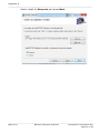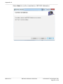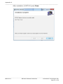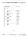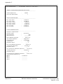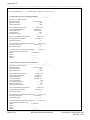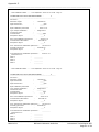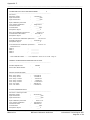
1
Instruction
Manual
BZ7002 Calibration
Software
BE6034-11
Index
________________________________________________________________________
Index
Index ................................................................................................................................... 2
Chapter 1 BZ7002 Calibration Software .................................................................................. 4
1.
Introduction .............................................................................................................. 5
Chapter 2 Installation of the BZ7002 ..................................................................................... 6
2.
Installation of the BZ7002 ........................................................................................... 7
2.1 Installing the BZ7002 Calibration Software. ................................................................ 7
2.1.1 Computer requirements ...................................................................................... 7
2.1.2 Installing BZ7002 .............................................................................................. 8
Chapter 3 Using the Program ................................................................................................ 9
3.
Using the Program.................................................................................................... 10
3.1 Program configuration ............................................................................................ 10
3.1.1 Communication interface .................................................................................. 11
3.1.2.1 The default unit values are: ............................................................................................................ 12
3.2 Gas monitor connect ................................................................................................. 13
3.3 Calibration Setup ................................................................................................... 13
3.3.1 Gas Name .......................................................................................................... 15
3.3.2 Active Bank ..................................................................................................... 15
3.3.3 Single or two-point calibration ........................................................................... 16
3.3.4 Water Vapour Concentration.............................................................................. 16
3.3.5 S.I.T. (Sample Integration Time) ....................................................................... 17
3.3.6 Flushing .......................................................................................................... 18
3.3.7 Calibration Type............................................................................................... 19
3.3.8 Operation........................................................................................................ 20
3.3.9 Calibration Measurement .................................................................................. 21
3.4 Check Measurements ............................................................................................. 22
3.4.1 Measurement Setup ......................................................................................... 22
3.4.2 Measurement Value .......................................................................................... 23
3.5 Documentation/Backup .......................................................................................... 25
3.6 Gas Monitor Calibration Data .................................................................................. 26
3.7 Service................................................................................................................. 27
Appendix A Installation Guide ............................................................................................. 28
Installation of BZ7002 ....................................................................................................... 29
Appendix B Gas Monitor Short Form Overview ...................................................................... 36
Appendix C Print Calibration Data Report View ...................................................................... 39
_______________________________________________________________________________
BE6034-11
BZ7002 Calibration Software
LumaSense Technologies A/S
Page 2 of 48
Index
________________________________________________________________________
Copyright © 2014 LumaSense Technologies A/S
All rights reserved. No part of this publication may be reproduced or
distributed in any form or by any means without prior consent in writing
from LumaSense Technologies A/S, Denmark.
_______________________________________________________________________________
BE6034-11
BZ7002 Calibration Software
LumaSense Technologies A/S
Page 3 of 48
Chapter 1
________________________________________________________________________
Chapter 1
BZ7002 Calibration Software
July 2014
_______________________________________________________________________________
BE6034-11
BZ7002 Calibration Software
LumaSense Technologies A/S
Page 4 of 48
Chapter 1
________________________________________________________________________
1.
Introduction
In some situations, it may be an advantage to calibrate the gas
monitor connecting it to a PC. The procedure to use the Gas-Monitor
as a stand-alone instrument is covered in the User Manual for the
Gas Monitor.
Please consult the User Manual for the Gas Monitor for guidance in
how to Install Optical Filters, Set- up and calibrate the Monitor.
This Manual only describes the use of the BZ7002 Calibration
Software during calibration, control measurements and back-up of
the calibration data.
BZ7002 will utilize the USB interface in the newer 1412i, 1314i and
3434i Gas Monitors:
To use the USB interface the Monitors serial number must be from:
1412i:
713-001
1314i:
702-001
3434i:
952-001
BZ7002 will also be able to run via the RS232 interface using the
older 1412i, 1314i, 3434i with lower serial numbers.
Furthermore the BZ7002 also runs via the RS232 interface with the
1412A, 1314A, 3434A models.
_______________________________________________________________________________
BE6034-11
BZ7002 Calibration Software
LumaSense Technologies A/S
Page 5 of 48
Chapter 2
________________________________________________________________________
Chapter 2
Installation of the BZ7002
July 2014
_______________________________________________________________________________
BE6034-11
BZ7002 Calibration Software
LumaSense Technologies A/S
Page 6 of 48
Chapter 2
________________________________________________________________________
2.
Installation of the BZ7002
When taking delivery of the Gas Monitor the BZ7002 Calibration
software is delivered on a CD.
2.1 Installing the BZ7002 Calibration Software.
2.1.1
Computer requirements
The Software is targeted to work on a Desktop/Laptop PC environment
running a Microsoft Windows Operating System.
Before installing the Software the PC must meet the following minimum
requirements:
Processor
Operating
System
Minimum: 2 gigahertz (GHz) dual core processor
Windows XP SP2
Windows 7
Windows 8
RAM
Minimum: 512 MB (XP) 2048 MB (7+8)
Hard Disk
Up to 500 MB of available space may be required.
Display
Minimum: 1024 x 768 highest colour, 32-bit
Total port
1 USB port Or
connections
1 RS232 port
Connection to 1 USB port
Gas Monitor Or
1 RS-232 port
Table 2.1 Computer requirements
_______________________________________________________________________________
BE6034-11
BZ7002 Calibration Software
LumaSense Technologies A/S
Page 7 of 48
Chapter 2
________________________________________________________________________
2.1.2
Installing BZ7002
Please refer to Appendix A how to perform the installation of the
BZ7002 Calibration software.
After the installation is successfully completed the LumaSense ->
BZ7002 menu is created.
The BZ7002 program icon (Figure 2.1) is also placed on your desktop
for easy access to the program.
Figure 2.1 BZ7002 Calibration desktop shortcut
_______________________________________________________________________________
BE6034-11
BZ7002 Calibration Software
LumaSense Technologies A/S
Page 8 of 48
Chapter 3
________________________________________________________________________
Chapter 3
Using the Program
July 2014
_______________________________________________________________________________
BE6034-11
BZ7002 Calibration Software
LumaSense Technologies A/S
Page 9 of 48
Chapter 3
_______________________________________________________________________
3.
Using the Program
The BZ7002 Calibration startup window will appear after starting the
application.
3.1 Program configuration
The very first time BZ7002 is started the Communication Interface and Units
needs to be configured.
The Configuration menu pull-down contains the Communication Interface and
Units menu items.
After making these configurations it is normally not necessary to change them
again, as the communication interface or the units is by preference.
The chosen configuration will be stored so they need not to be set when
restarting BZ7002.
_______________________________________________________________________________
BE6034-11
BZ7002 Calibration Software
LumaSense Technologies A/S
Page 10 of 48
Chapter 3
_______________________________________________________________________
3.1.1
Communication interface
The USB interface or a serial (RS232) COM port can be chosen.
When using the new 1412i the USB interface should be used.
When using the older 1412i, 1314i, 3434i or the 1412A, 1314A, 3434A the serial
(RS232) COM interface should be used.
The selected communication interface setting will be retained when restarting
the BZ7002 Calibration.
_______________________________________________________________________________
BE6034-11
BZ7002 Calibration Software
LumaSense Technologies A/S
Page 11 of 48
Chapter 3
_______________________________________________________________________
3.1.2
Units
The selected units will be used when calculating the respective values for:
-
Humidity
-
Pressure
-
Gas Concentration
-
Temperature
-
Length
The selected normalization temperature will be used when calibration is
performed.
3.1.2.1
The default unit values are:
-
Humidity : Tdew
-
Pressure : mBar
-
Gas Concentration : ppm
-
Temperature : °C
-
Length : m
The default normalization temperature is 20 °C.
The selected unit and normalization temperature settings will be retained when
restarting the BZ7002 Calibration.
_______________________________________________________________________________
BE6034-11
BZ7002 Calibration Software
LumaSense Technologies A/S
Page 12 of 48
Chapter 3
_______________________________________________________________________
3.2 Gas monitor connect
In order to connect to the Gas Monitor the file menu item Connect can be used.
The configured communication interface will be used when connecting to the gas
monitor.
In case of a failed connect a popup error message box will be displayed.
After a successful connection to the Gas Monitor the Calibration Setup tab (see
next section) becomes visible.
The Configuration file menu will be inactive (not changeable) after connecting
to the Gas Monitor, implying that neither the Communication Interface nor
the Units can be changed while the BZ7002 Calibration is connected with the
Gas Monitor.
While connected the Gas Monitor keyboard will be inactive.
3.3 Calibration Setup
The main purpose of the Setup tab is to configure and select the different
calibration types.
Furthermore the measurement can be setup.
The UA filters available in the Gas Monitor are automatically detected, when
connecting to the Gas Monitor.
_______________________________________________________________________________
BE6034-11
BZ7002 Calibration Software
LumaSense Technologies A/S
Page 13 of 48
Chapter 3
_______________________________________________________________________
This means that the UA filters needs to be predefined, by beforehand setting the
filter UA numbers in the Gas Monitor itself Please consult the Gas Monitor User
Manual for further instructions.
The table column UA no. will display the detected UA filter numbers.
Furthermore the Gas Name and Mol. Wgt. values will be displayed if they are
available in the Gas Monitor.
For the filters A-E, where an UA filter is detected, the following columns becomes
active (changeable):
- Active Bank
- Gas Name
- Mol. Wgt. (Molecular weight of the gas)
- Cal. 1-/2-Points (Single or two-point calibration)
- Conc. High
- Conc Low ( if a 2 point calibration is selected)
- S.I.T. (Sample integration time)
For the rest of the filters A-E, where an UA filter is not detected the respective
column values, becomes inactive (not changeable).
Any illegal input entered in the numeric data fields (like the Mol. Wgt. or Conc.
High) will be marked with red color and a PC beep will be heard.
_______________________________________________________________________________
BE6034-11
BZ7002 Calibration Software
LumaSense Technologies A/S
Page 14 of 48
Chapter 3
_______________________________________________________________________
3.3.1 Gas Name
The Gas Name cannot contain illegal characters like special country characters
and the maximum length is 29 characters.
Illegal Gas Name’s will be marked with red color and a PC beep will be heard.
3.3.2
Active Bank
For each of the filters A-E the Active Bank can be chosen by using the Active
Bank pull-down for the filter in question. The selected row (1-5) in the Active
Bank pull-down determines the active bank (1-5) for the filter.
Each active bank (1-5) will contain its own set of the following parameters:
-
Gas Name
Mol. Wgt. (Molecular weight of the gas)
Cal. 1-/2-Points (Single or two-point calibration)
Conc. High
Conc. Low
_______________________________________________________________________________
BE6034-11
BZ7002 Calibration Software
LumaSense Technologies A/S
Page 15 of 48
Chapter 3
_______________________________________________________________________
3.3.3
Single or two-point calibration
Single point or two-point calibration can be chosen for every bank for each filter.
When two-point calibration is chosen, the Conc. Low field becomes active
(changeable).
3.3.4
Water Vapour Concentration
The concentration used when span calibrating the Water Vapour filter can be
defined.
The default concentration comes predefined as 18 Tdew °C / 291.15 Tdew K /
64.40 Tdew °F / 15254.15 mg/m³ / 20361.55 ppm / 2.06 kPa.
_______________________________________________________________________________
BE6034-11
BZ7002 Calibration Software
LumaSense Technologies A/S
Page 16 of 48
Chapter 3
_______________________________________________________________________
3.3.5
S.I.T. (Sample Integration Time)
The S.I.T. (Sample Integration Time) can be set individually for each of the filter
A to W, with a predefined value of 5 seconds.
The choice of S.I.T. values are
-
0.5 second
-
1 second (Fast)
-
2 seconds
-
5 seconds (Normal)
-
10 seconds
-
20 seconds (Low noise)
-
50 seconds
-
_______________________________________________________________________________
BE6034-11
BZ7002 Calibration Software
LumaSense Technologies A/S
Page 17 of 48
Chapter 3
_______________________________________________________________________
3.3.6
Flushing
Auto(matic) or Fixed Time flushing of the gas can be selected.
For Auto-flushing the Tube Length can be defined.
For Fixed Time-flushing the Chamber- and Tube-flush time can be defined.
The default, minimum and maximum values for all the flush settings are:
Default
Flushing
Minimum Maximum
Auto
Auto
Tube
Length
1 meter
0 meter
99 meter
Fixed
Time
Chamber
flush time
8
seconds
2 seconds
60 seconds
flush 3
seconds
3 seconds
120
seconds
Tube
time
The flush settings will not be retained after restarting the BZ7002 Calibration.
When Auto-flushing is selected the Chamber: and Tube: settings for Fixed
Time-flushing will be in-active (not changeable, and vice versa when Fixed
Time-flushing is selected.
_______________________________________________________________________________
BE6034-11
BZ7002 Calibration Software
LumaSense Technologies A/S
Page 18 of 48
Chapter 3
_______________________________________________________________________
3.3.7
Calibration Type
In the Calibration Type group box the type of calibration to be performed can
be selected.
Only one of the calibration types can be selected at a time.
The Zero+Humidity Interference calibration is a combined zero and humidity
interference calibration performed in the same session. This combined calibration
should be performed on a new Gas-monitor the first time it is to be calibrated
and also if a new optical filter is installed.
For the Gas Span calibration the choice of gasses ( already set-up in the Gasmonitor) will show the filters A-E, where a UA number is set in the gas monitor.
For each filter the active bank determines a specific gas.
The Perform Cross Interference Calibration tick-box becomes active, when
the Gas Span calibration is selected.
The Perform Cross Interference Calibration checkbox is to be ticked (Cross
interference compensation is on), if 2 or more of the filters A-E have UA filters
installed and if cross interference compensation is to be used during
measurement. If only one filter is installed then the Perform Cross
Interference Calibration checkbox will be un-ticked and inactive (not
changeable).
By clicking the Copy Active Bank to all other banks-button you are able to
copy the Zero-calibration and Humidity Interference-calibration, from the active
_______________________________________________________________________________
BE6034-11
BZ7002 Calibration Software
LumaSense Technologies A/S
Page 19 of 48
Chapter 3
_______________________________________________________________________
bank to all the other banks for a filter. This will be done for all of the filters A-E,
having UA filters installed.
3.3.8
Operation
The selected Calibration Type will be performed when pressing the Start
Calibration-button and the Calibration Measurement Values tab will be
shown. Furthermore the Accept- and Cancel Operation-buttons becomes
active. The Calibration Measurement Values-tab is described in the next
section.
When pressing the Start Measurement-button, the Measurement Values-tab
will be shown. Furthermore the Cancel Operation-button becomes active. The
Measurement Values-tab is described in the Measurement Values-section.
During calibration measurement or calibration check the progress bar becomes
active.
The Calibration Status list-box will display progress information and ask the
user to connect a particular gas when needed during a calibration.
The Cancel-button aborts the current job and the actual calibration was not
performed.
_______________________________________________________________________________
BE6034-11
BZ7002 Calibration Software
LumaSense Technologies A/S
Page 20 of 48
Chapter 3
_______________________________________________________________________
3.3.9
Calibration Measurement
The purpose of the Calibration Measurement Values-tab is to monitor the
filter calibration values and accept the current calibration in progress, when
within the necessary limits.
During calibration measurement the following parameters will be shown (for
available filters only) in a table list:
-
Number: Measurement number
Temp: Chamber Temperature
A mean’: Mean µV value (rolling average for up to the last
values) for the A filter.
A StDev: Standard deviation µV value for the A filter.
B mean: Mean µV value (rolling average for up to the last
values) for the B filter.
B StDev: Standard deviation µV value for the B filter.
C mean: Mean µV value (rolling average for up to the last
values) for the C filter.
C StDev: Standard deviation µV value for the C filter
D mean: Mean µV value (rolling average for up to the last
values) for the D filter.
D StDev: Standard deviation µV value for the D filter.
E mean: Mean µV value (rolling average for up to the last
values) for the E filter.
E StDev: Standard deviation µV value for the E filter.
W mean: Mean µV value (rolling average for up to the last
values) for the Water filter.
W StDev: Standard deviation µV value for the Water filter
6 measured
6 measured
6 measured
6 measured
6 measured
6 measured
_______________________________________________________________________________
BE6034-11
BZ7002 Calibration Software
LumaSense Technologies A/S
Page 21 of 48
Chapter 3
_______________________________________________________________________
In the Calibration Status list-box, status information will be shown.
Furthermore the user will be prompted to connect a certain gas, by a message in
the Calibration Status list-box. When the gas is connected to the gas monitor,
the user acknowledges this by clicking the Accept button.
When the user is satisfied with the calibration measurement values, the current
calibration can be accepted by clicking the Accept button.
After accepting a calibration the Gas Monitor will signal, whether the actual
calibration is approved or not and the result is presented in the Calibration
Status list-box.
At any time the user can abort the calibration by clicking the Cancel Operation
button and the actual calibration was then not performed.
During a calibration measurement by BZ7002 Calibration the buttons on the
gas monitor will be locked, meaning that the Gas Monitor itself cannot be
operated during a calibration. When calibration is finished the gas monitor
buttons are unlocked again.
3.4 Check Measurements
3.4.1
Measurement Setup
After calibrating one or more gases the calibration can be validated by
performing a check measurement.
The Measurement Setup selects which of the filters A-W shall be included in
the check measurement and whether Water or Cross compensation shall be
performed during the check measurement.
_______________________________________________________________________________
BE6034-11
BZ7002 Calibration Software
LumaSense Technologies A/S
Page 22 of 48
Chapter 3
_______________________________________________________________________
3.4.2
Measurement Value
The purpose of the Measurement Values-tab is to be able to make check
measurements, after having calibrated the gas monitor.
During check measurement the following parameters will be shown (for available
filters only) in a table list:
-
Number: Measurement number
A Inst: Instantaneous gas A concentration value.
A mean: Mean gas A concentration value (current
average).
A StDev: Standard deviation value for gas A.
B Inst: Instantaneous gas B concentration value.
B mean: Mean gas B concentration value (current
average).
B StDev: Standard deviation value for gas B.
C Inst: Instantaneous gas C concentration value.
C mean: Mean gas C concentration value (current
average).
C StDev: Standard deviation value for gas C.
D Inst: Instantaneous gas D concentration value.
D mean: Mean gas D concentration value (current
average).
D StDev: Standard deviation value for gas D.
E Inst: Instantaneous gas E concentration value.
E mean: Mean gas E concentration value (current
average).
unit, 10 value rolling
unit, 10 value rolling
unit, 10 value rolling
unit, 10 value rolling
unit, 10 value rolling
_______________________________________________________________________________
BE6034-11
BZ7002 Calibration Software
LumaSense Technologies A/S
Page 23 of 48
Chapter 3
_______________________________________________________________________
-
E StDev: Standard deviation value for gas E.
W Inst: Instantaneous water concentration value.
W mean: Mean water value (current unit, 10 value rolling average).
W StDev: Standard deviation value for water.
Event Mark: Events marks added by the user.
The idea behind the Measurement Values-tab is to be able to connect Zero-,
Water Vapour- and Span-gasses one at a time, while checking that the
concentration values being measured is within expected limits.
When the user is finished checking the gas and water values, the check
operation can be finished by clicking the Cancel Operation- button.
The gas concentration unit for the filters A-E and the water (filter W)
concentration unit will be shown in the header of the Measurement Valuestab.
In order for the user to be able to mark measurements with specific events
during the calibration check measurement, the Insert Event Mark-button and
the accompanying text-box can be used.
The event mark will be added to the next measurement.
The check measurement can be restarted by using the Restart Measurementbutton. This could be used if the wrong control gas was connected to the gas
monitor and the user wants to restart the check measurement.
_______________________________________________________________________________
BE6034-11
BZ7002 Calibration Software
LumaSense Technologies A/S
Page 24 of 48
Chapter 3
_______________________________________________________________________
3.5 Documentation/Backup
The purpose of the Documentation/Backup-tab
backup/restore a gas monitor calibration.
is
to
document
and
The Measurement Log-button makes a log file of all the calibration- and checkmeasurements results, during the session with the gas monitor. The log file will
be saved as a text file.
The Print Calibration Data-button gives a detailed report-view of all the filter
calibrations in every bank. It will be possible to print and save the report-view as
a file. See Appendix C for a sample of the Print Calibration Data.
The Gas Monitor Shortform Overview-button gives a short report-view of all
the filter calibrations in every bank. It will be possible to print and save the
report-view as a file. See Appendix B for a sample of the Gas Monitor Setup.
The Backup Gas Monitor Calibration Data-button makes a backup of all the
calibration data in the Gas Monitor. The name of the backup file will be the serial
number of the gas monitor and file type will be .cal.
This gas-monitor backup is saved to a file, which can be later restored using the
Restore Gas Monitor Calibration Data-button, if for example the gas monitor
calibration is lost. The serial number and filter UA numbers of the gas monitor
must match the same in the backup file, in order for the restore to be possible.
Furthermore this gas-monitor backup is checksum-protected, making it invalid if
it has been tampered with.
_______________________________________________________________________________
BE6034-11
BZ7002 Calibration Software
LumaSense Technologies A/S
Page 25 of 48
Chapter 3
_______________________________________________________________________
After the calibration data has been restored the Gas Monitor stores the
calibration data in a non-volatile memory. The user is warned (message below)
not to switch off the power supply of the Gas Monitor, but is prompted to wait 10
seconds, while the calibration data is being stored in the non-volatile memory.
3.6 Gas Monitor Calibration Data
The purpose of the Gas Monitor Calibration Data-tab is to inspect/modify the
calibration data for the gas monitor.
The calibration data is read from the gas monitor by clicking the Read
Calibration Data-button.
The calibration data can be modified by entering the editable calibration data
fields.
The calibration Date fields will not be editable (not changeable).
The Filter combo-box can be used to switch between filter A, B, C, D, E and W.
_______________________________________________________________________________
BE6034-11
BZ7002 Calibration Software
LumaSense Technologies A/S
Page 26 of 48
Chapter 3
_______________________________________________________________________
When inspection/modification of the calibration data is finished, they can be
written back to the gas monitor, by clicking the Write Calibration Data-button.
After the calibration data has been written back to the Gas Monitor, it stores the
calibration data in the non-volatile memory. The user is warned not to switch off
the power supply of the Gas Monitor, but is prompted to wait 10 seconds, while
the calibration data is being stored in non-volatile memory.
3.7 Service
For service use it is possible to create a file containing debug information by
selecting the Service menu item Create Debug Info Zip File.
When selected an explorer window opens where you can select a folder for the
file to be saved.
The file can then be emailed to LumaSense/Innova Service for inspection during
support handling.
_______________________________________________________________________________
BE6034-11
BZ7002 Calibration Software
LumaSense Technologies A/S
Page 27 of 48
Chapter 3
________________________________________________________________________
Appendix A
Installation Guide
July 2014
_______________________________________________________________________________
BE6034-11
BZ7002 Calibration Software
LumaSense Technologies A/S
Page 28 of 48
Appendix A
_______________________________________________________________________
Installation of BZ7002
1. When installing the BZ7002 Calibration software you must be
logged in as Administrator that means that you must have
“administrator” rights.
Please also note that you must have Administrator rights or
Power User rights to run the BZ7002 Calibration application
after installation.
2. Start the installation of BZ7002. Insert the CD into the CD-drive and
wait for auto-start of the CD. If auto-start is disabled run
BZ7002v1.0.xInstaller.exe self-executable file on the installation
CD to start the installation. It will automatically install all the
necessary drivers required to run the BZ7002 application. The
installer will start unpacking with the following window. Please wait.
After a while the following window appears. Press the OK button to
continue:
3. First you are prompted to install the USB driver to enable the PC to
communicate with the gas monitor through the USB interface.
_______________________________________________________________________________
BE6034-11
BZ7002 Calibration Software
LumaSense Technologies A/S
Page 29 of 48
Appendix A
_______________________________________________________________________
If the USB driver has been installed due to a previous BZ7002
installation you can skip this by pressing the Cancel-button otherwise
please press the OK-button to continue.
Press Next to continue.
_______________________________________________________________________________
BE6034-11
BZ7002 Calibration Software
LumaSense Technologies A/S
Page 30 of 48
Appendix A
_______________________________________________________________________
Press Finish to continue
4. Then you are prompted to install the driver for the JV0901 USB to
RS232 converter.
If the USB driver has been installed due to a previous BZ7002
installation you can skip this by pressing the Cancel-button otherwise
please press the OK-button to continue.
Press OK to continue.
_______________________________________________________________________________
BE6034-11
BZ7002 Calibration Software
LumaSense Technologies A/S
Page 31 of 48
Appendix A
_______________________________________________________________________
Now wait for the following window to disappear
5. Finally the BZ7002 application is installed.
installation of BZ7002 Calibration.
Press Next to start
_______________________________________________________________________________
BE6034-11
BZ7002 Calibration Software
LumaSense Technologies A/S
Page 32 of 48
Appendix A
_______________________________________________________________________
Select install for Everyone and press Next
_______________________________________________________________________________
BE6034-11
BZ7002 Calibration Software
LumaSense Technologies A/S
Page 33 of 48
Appendix A
_______________________________________________________________________
Select Next to confirm installation of BZ7002 Calibration
_______________________________________________________________________________
BE6034-11
BZ7002 Calibration Software
LumaSense Technologies A/S
Page 34 of 48
Appendix A
_______________________________________________________________________
After installation of BZ7002 press Close.
_______________________________________________________________________________
BE6034-11
BZ7002 Calibration Software
LumaSense Technologies A/S
Page 35 of 48
Appendix B
________________________________________________________________________
Appendix B
Gas Monitor Short Form Overview
July 2014
_______________________________________________________________________________
BE6034-11
BZ7002 Calibration Software
LumaSense Technologies A/S
Page 36 of 48
Appendix B
________________________________________________________________________
Sample of the Gas Monitor Short-form Overview with filter A and B installed:
_______________________________________________________________________________
BE6034-11
BZ7002 Calibration Software
LumaSense Technologies A/S
Page 37 of 48
Appendix B
________________________________________________________________________
The UA-numbers for the mounted filters is shown. For each filter the Gas Name’s
in each bank is presented where available. The A,B,C,D,E columns denotes
available cross interference factors, where a ‘X’ means present and a ‘0’ means
that it is nulled. The ‘1/2’-column denotes whether a single- or two-pint
calibration is available.
_______________________________________________________________________________
BE6034-11
BZ7002 Calibration Software
LumaSense Technologies A/S
Page 38 of 48
Appendix C
_______________________________________________________________________
Appendix C
Print Calibration Data Report View
July 2014
_______________________________________________________________________________
BE6034-11
BZ7002 Calibration Software
LumaSense Technologies A/S
Page 39 of 48
Appendix C
_______________________________________________________________________
Sample of the Print Calibration Data report-view with filter A and B installed:
_______________________________________________________________________________
BE6034-11
BZ7002 Calibration Software
LumaSense Technologies A/S
Page 40 of 48
Appendix C
_______________________________________________________________________
- 1412i Calibration Data ------- 712-008/9999 - 2014-07-01 13:58 - Page 1 -
GENERAL CALIBRATION INFORMATION FOR FILTER A.
--------------------------------------------------------------------------Installed Optical Filter
Active Filter Bank Number
:
UA0983
1
:
OPTICAL FILTER FACTORS
--------------------------------------------------------------------------Back. temp. factor
:
17.449E-03
Conc. temp. factor
:
5.9198E-03
Hum. temp. 1 factor
:
-15.99E-03
Hum. temp. 2 factor
:
-17.87E-03
Hum. temp. 3 factor
:
0.0000E+00
Hum. sqr. factor
:
-1.243E+03
Hum. cub. factor
:
0.0000E+00
ACTIVE CALIBRATION DATA
--------------------------------------------------------------------------Gas name : Carbon dioxide
Molecular weight
:
44.010E+00
High Alarm limit 1
:
_______ ppm
High Alarm limit 2
:
_______ ppm
Span Calibration performed
Type of Span Calibration
Conversion factor
Concentration
Microphone Signal
Zero-Point Calibration performed
Concentration offset factor
Microphone Signal
:
:
:
:
:
2014-07-01
Single Point
19.222E+06
____ ppm
____ V
:
:
:
2014-07-01
813.81E-09
____ V
Hum. Interference Calibration performed :
2014-07-01
Humidity gain factor
:
42.821E-03
Microphone Signal
:
____ V
Cross Interference Calibration performed :
2014-07-01
Carbon dioxide interference on :
Filter B
:
1.9174E+06
Filter C
:
__________
Filter D
:
__________
Filter E
:
__________
_______________________________________________________________________________
BE6034-11
BZ7002 Calibration Software
LumaSense Technologies A/S
Page 41 of 48
Appendix C
_______________________________________________________________________
- 1412i Calibration Data ------- 712-008/9999 - 2014-07-01 13:58 - Page 2 -
CALIBRATION DATA IN FILTER BANK NUMBER :
1
--------------------------------------------------------------------------Gas name : Carbon dioxide
Molecular weight
:
44.010E+00
High Alarm limit 1
:
____ ppm
High Alarm limit 2
:
____ ppm
Span Calibration performed
Type of Span Calibration
Conversion factor
Concentration
Microphone Signal
Zero-Point Calibration performed
Concentration offset factor
Microphone Signal
:
:
:
:
:
2014-07-01
Single Point
19.222E+06
____ ppm
____ V
:
:
:
2014-07-01
813.81E-09
____ V
Hum. Interference Calibration performed :
2014-07-01
Humidity gain factor
:
42.821E-03
Microphone Signal
:
____ V
Cross Interference Calibration performed :
2014-07-01
Carbon dioxide interference on :
Filter B
:
1.9174E+06
Filter C
:
__________
Filter D
:
__________
Filter E
:
__________
CALIBRATION DATA IN FILTER BANK NUMBER :
2
--------------------------------------------------------------------------Gas name : Carbon dioxide
Molecular weight
:
44.010E+00
High Alarm limit 1
:
____ ppm
High Alarm limit 2
:
____ ppm
Span Calibration performed
Type of Span Calibration
Conversion factor 1
Conversion factor 2
Low Concentration
Low Microphone Signal
High Concentration
High Microphone Signal
Zero-Point Calibration performed
Concentration offset factor
Microphone Signal
:
2014-07-01
Two Point
5.8783E-03
5.0755E-06
____ ppm
____ V
____ ppm
____ V
:
:
:
:
:
:
:
:
:
:
2014-07-01
813.81E-09
____ V
Hum. Interference Calibration performed :
2014-07-01
Humidity gain factor
:
42.821E-03
Microphone Signal
:
____ V
Cross Interference Calibration performed :
2014-07-01
Carbon dioxide interference on :
Filter B
:
0.0000E+00
Filter C
:
__________
Filter D
:
__________
Filter E
:
__________
_______________________________________________________________________________
BE6034-11
BZ7002 Calibration Software
LumaSense Technologies A/S
Page 42 of 48
Appendix C
_______________________________________________________________________
- 1412i Calibration Data ------- 712-008/9999 - 2014-07-01 13:58 - Page 3 CALIBRATION DATA IN FILTER BANK NUMBER :
3
--------------------------------------------------------------------------Gas name : _
Molecular weight
:
1.0000E+00
High Alarm limit 1
:
____ ppm
High Alarm limit 2
:
____ ppm
Span Calibration performed
Type of Span Calibration
Conversion factor
Concentration
Microphone Signal
Zero-Point Calibration performed
Concentration offset factor
Microphone Signal
:
:
:
:
:
2014-07-01
Single Point
__________
____ ppm
____ V
:
:
:
2014-07-01
813.00E-09
____ V
Hum. Interference Calibration performed :
2014-07-01
Humidity gain factor
:
42.821E-03
Microphone Signal
:
____ V
Cross Interference Calibration performed :
2014-07-01
_ interference on :
Filter B
:
__________
Filter C
:
__________
Filter D
:
__________
Filter E
:
__________
- 1412i Calibration Data ------- 712-008/9999 - 2014-07-01 13:58 - Page 4 -
CALIBRATION DATA IN FILTER BANK NUMBER :
4
--------------------------------------------------------------------------Gas name : _
Molecular weight
:
1.0000E+00
High Alarm limit 1
:
____ ppm
High Alarm limit 2
:
____ ppm
Span Calibration performed
Type of Span Calibration
Conversion factor
Concentration
Microphone Signal
Zero-Point Calibration performed
Concentration offset factor
Microphone Signal
:
:
:
:
:
__________
Single Point
__________
____ ppm
____ V
:
:
:
2014-07-01
813.00E-09
____ V
Hum. Interference Calibration performed :
2014-07-01
Humidity gain factor
:
42.821E-03
Microphone Signal
:
____ V
Cross Interference Calibration performed :
__________
_ interference on :
Filter B
:
__________
Filter C
:
__________
Filter D
:
__________
Filter E
:
__________
_______________________________________________________________________________
BE6034-11
BZ7002 Calibration Software
LumaSense Technologies A/S
Page 43 of 48
Appendix C
_______________________________________________________________________
CALIBRATION DATA IN FILTER BANK NUMBER :
5
--------------------------------------------------------------------------Gas name : _
Molecular weight
:
1.0000E+00
High Alarm limit 1
:
____ ppm
High Alarm limit 2
:
____ ppm
Span Calibration performed
Type of Span Calibration
Conversion factor
Concentration
Microphone Signal
:
:
:
:
:
Zero-Point Calibration performed
Concentration offset factor
Microphone Signal
__________
Single Point
__________
____ ppm
____ V
:
:
:
2014-07-01
813.00E-09
____ V
Hum. Interference Calibration performed :
2014-07-01
Humidity gain factor
:
42.821E-03
Microphone Signal
:
____ V
Cross Interference Calibration performed :
2014-07-01
_ interference on :
Filter B
:
__________
Filter C
:
__________
Filter D
:
__________
Filter E
:
__________
- 1412i Calibration Data ------- 712-008/9999 - 2014-07-01 13:58 - Page 5 -
GENERAL CALIBRATION INFORMATION FOR FILTER B.
--------------------------------------------------------------------------Installed Optical Filter
Active Filter Bank Number
:
:
UA0985
1
OPTICAL FILTER FACTORS
--------------------------------------------------------------------------Back. temp. factor
:
2.6707E-03
Conc. temp. factor
:
7.6043E-03
Hum. temp. 1 factor
:
-9.427E-03
Hum. temp. 2 factor
:
-1.483E-03
Hum. temp. 3 factor
:
0.0000E+00
Hum. sqr. factor
:
-944.0E+00
Hum. cub. factor
:
0.0000E+00
ACTIVE CALIBRATION DATA
--------------------------------------------------------------------------Gas name : Dinitrogen oxide
Molecular weight
:
44.010E+00
High Alarm limit 1
:
_______ ppm
High Alarm limit 2
:
_______ ppm
Span Calibration performed
Type of Span Calibration
Conversion factor
Concentration
Microphone Signal
:
:
:
:
:
2014-07-01
Single Point
168.62E+03
____ ppm
____ V
_______________________________________________________________________________
BE6034-11
BZ7002 Calibration Software
LumaSense Technologies A/S
Page 44 of 48
Appendix C
_______________________________________________________________________
Zero-Point Calibration performed
Concentration offset factor
Microphone Signal
:
:
:
2014-07-01
3.0503E-06
____ V
Hum. Interference Calibration performed :
2014-07-01
Humidity gain factor
:
53.574E-03
Microphone Signal
:
____ V
Cross Interference Calibration performed :
2014-06-26
Dinitrogen oxide interference on :
Filter A
:
376.34E+06
Filter C
:
__________
Filter D
:
__________
Filter E
:
__________
- 1412i Calibration Data ------- 712-008/9999 - 2014-07-01 13:58 - Page 6 -
CALIBRATION DATA IN FILTER BANK NUMBER :
1
--------------------------------------------------------------------------Gas name : Dinitrogen oxide
Molecular weight
:
44.010E+00
High Alarm limit 1
:
____ ppm
High Alarm limit 2
:
____ ppm
Span Calibration performed
Type of Span Calibration
Conversion factor
Concentration
Microphone Signal
Zero-Point Calibration performed
Concentration offset factor
Microphone Signal
:
:
:
:
:
2014-07-01
Single Point
168.62E+03
____ ppm
____ V
:
:
:
2014-07-01
3.0503E-06
____ V
Hum. Interference Calibration performed :
2014-07-01
Humidity gain factor
:
53.574E-03
Microphone Signal
:
____ V
Cross Interference Calibration performed :
2014-06-26
Dinitrogen oxide interference on :
Filter A
:
376.34E+06
Filter C
:
__________
Filter D
:
__________
Filter E
:
__________
CALIBRATION DATA IN FILTER BANK NUMBER :
2
--------------------------------------------------------------------------Gas name : _
Molecular weight
:
1.0000E+00
High Alarm limit 1
:
____ ppm
High Alarm limit 2
:
____ ppm
Span Calibration performed
Type of Span Calibration
Conversion factor
Concentration
Microphone Signal
Zero-Point Calibration performed
Concentration offset factor
Microphone Signal
:
:
:
:
:
__________
Single Point
__________
____ ppm
____ V
:
:
:
2014-07-01
3.0503E-06
____ V
_______________________________________________________________________________
BE6034-11
BZ7002 Calibration Software
LumaSense Technologies A/S
Page 45 of 48
Appendix C
_______________________________________________________________________
Hum. Interference Calibration performed :
2014-07-01
Humidity gain factor
:
53.574E-03
Microphone Signal
:
____ V
Cross Interference Calibration performed :
__________
_ interference on :
Filter A
:
__________
Filter C
:
__________
Filter D
:
__________
Filter E
:
__________
- 1412i Calibration Data ------- 712-008/9999 - 2014-07-01 13:58 - Page 7 CALIBRATION DATA IN FILTER BANK NUMBER :
3
--------------------------------------------------------------------------Gas name : _
Molecular weight
:
1.0000E+00
High Alarm limit 1
:
____ ppm
High Alarm limit 2
:
____ ppm
Span Calibration performed
Type of Span Calibration
Conversion factor
Concentration
Microphone Signal
Zero-Point Calibration performed
Concentration offset factor
Microphone Signal
:
:
:
:
:
__________
Single Point
__________
____ ppm
____ V
:
:
:
2014-07-01
3.0503E-06
____ V
Hum. Interference Calibration performed :
2014-07-01
Humidity gain factor
:
53.574E-03
Microphone Signal
:
____ V
Cross Interference Calibration performed :
__________
_ interference on :
Filter A
:
__________
Filter C
:
__________
Filter D
:
__________
Filter E
:
__________
CALIBRATION DATA IN FILTER BANK NUMBER :
4
--------------------------------------------------------------------------Gas name : _
Molecular weight
:
1.0000E+00
High Alarm limit 1
:
____ ppm
High Alarm limit 2
:
____ ppm
Span Calibration performed
Type of Span Calibration
Conversion factor
Concentration
Microphone Signal
Zero-Point Calibration performed
Concentration offset factor
Microphone Signal
:
:
:
:
:
__________
Single Point
__________
____ ppm
____ V
:
:
:
2014-07-01
3.0503E-06
____ V
Hum. Interference Calibration performed :
2014-07-01
Humidity gain factor
:
53.574E-03
Microphone Signal
:
____ V
Cross Interference Calibration performed :
_ interference on :
__________
_______________________________________________________________________________
BE6034-11
BZ7002 Calibration Software
LumaSense Technologies A/S
Page 46 of 48
Appendix C
_______________________________________________________________________
Filter
Filter
Filter
Filter
A
C
D
E
:
:
:
:
__________
__________
__________
__________
- 1412i Calibration Data ------- 712-008/9999 - 2014-07-01 13:58 - Page 8 CALIBRATION DATA IN FILTER BANK NUMBER :
5
--------------------------------------------------------------------------Gas name : _
Molecular weight
:
1.0000E+00
High Alarm limit 1
:
____ ppm
High Alarm limit 2
:
____ ppm
Span Calibration performed
Type of Span Calibration
Conversion factor
Concentration
Microphone Signal
Zero-Point Calibration performed
Concentration offset factor
Microphone Signal
:
:
:
:
:
__________
Single Point
__________
____ ppm
____ V
:
:
:
2014-07-01
3.0503E-06
____ V
Hum. Interference Calibration performed :
2014-07-01
Humidity gain factor
:
53.574E-03
Microphone Signal
:
____ V
Cross Interference Calibration performed :
__________
_ interference on :
Filter A
:
__________
Filter C
:
__________
Filter D
:
__________
Filter E
:
__________
- 1412i Calibration Data ------- 712-008/9999 - 2014-07-01 13:58 - Page 9 GENERAL CALIBRATION INFORMATION FOR WATER FILTER.
--------------------------------------------------------------------------WATER FILTER FACTORS
--------------------------------------------------------------------------Back. temp. factor
:
814.20E-06
Conc. temp. factor
:
-4.301E-03
Hum. sqr. factor
:
2.4070E-06
ACTIVE CALIBRATION DATA
--------------------------------------------------------------------------High Alarm limit 1
:
_______ Tdew
High Alarm limit 2
:
_______ Tdew
Span Calibration performed
Conversion factor
Concentration
Microphone Signal
Zero-Point Calibration performed
Concentration offset factor
Microphone Signal
:
:
:
:
2014-06-17
24.263E-09
____ ppm
____ V
:
:
:
2014-06-18
6.5934E-06
____ V
_______________________________________________________________________________
BE6034-11
BZ7002 Calibration Software
LumaSense Technologies A/S
Page 47 of 48
BZ7002
LumaSense Technologies A/S
Energivej 30
DK-2750 Ballerup, Denmark
Tel.:(+45) 44 20 01 00
Fax: (+45) 44 20 01 01
http://www.lumasenseinc.com