1
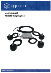
User Manual Agreto Heavy Duty Modules 4x 5t/10t/15t 26.03.2014 © AGRETO electronics GmbH AGRETO Heavy Duty Modules Content 1 2 3 4 5 6 7 8 9 10 11 12 13 14 15 Introduction ........................................................................................................... 3 Scope of delivery .................................................................................................. 3 Intended use ......................................................................................................... 3 Security ................................................................................................................. 4 Technical Specifications ....................................................................................... 6 Mounting the Agreto heavy duty modules............................................................ 7 Mounting the construction .................................................................................... 8 Adjustment of the lift lock ..................................................................................... 9 Junction box ....................................................................................................... 10 Connecting the Weighing Indicator .................................................................... 11 Troubleshooting .................................................................................................. 11 Warranty ............................................................................................................. 12 Disposal .............................................................................................................. 13 Declaration of Conformity ................................................................................... 14 Imprint ................................................................................................................. 15 © AGRETO electronics GmbH Seite:2 Seite:2 AGRETO Heavy Duty Modules 1 Introduction Thank you for choosing Agreto heavy duty modules. You have acquired rugged weighing technology for everyday practical use. Please read this manual carefully before taking the weighing equipment in operation. In this manual, as usual "weight" is used in common parlance, the term for the mass. 2 Scope of delivery The delivery of a set of 4 modules include: 4 Load cells 4 Movable load feet 4 Ground plates 4 Top plates 8 Lift locks Screws and fixing material 1 Junction box 10m Connection cable to the display This manual A weighing system can consist of 3 to 8 modules. 3 Intended use The Agreto heavy duty modules can be used universally. Through the integrated liftlock and by the inclusion of lateral forces by the load application design, they can be mounted on any type of silos, containers, feed mixer, or other constructions. The load cells are made of alloy steel, the mounting plates made of galvanized steel. The load cells can be connected to all common weighing displays. © AGRETO electronics GmbH Seite:3 Seite:3 AGRETO Heavy Duty Modules 4 Security 4.1 Safety Instructions for the buyer IMPORTANT! Make sure that each person who works for the first time with the product, has read and understood this manual. 4.2 Safety instructions for the operator DANGER! Die AGRETO heavy duty modules may only be operated by persons who are familiar with the operation of the device. PRECAUTION! Keep the work area clean! Soiled areas contributes to accidents. PRECAUTION! Note the crushing hazard for the establishment and handling with the weighing construction. PRECAUTION! Note the risk of injury from stumbling and inattention while the assembly, disassembly, and adjustment operations. © AGRETO electronics GmbH Seite:4 Seite:4 AGRETO Heavy Duty Modules For persons who are engaged in the assembly, dismantling or adjustments, the wearing of safety shoes are required. For persons who are engaged in the assembly, dismantling or adjustments, the wearing of protective gloves is mandatory. 4.3 Residual Hazards Working with the device residual risks may arise for persons and objects that cannot be prevented by design or technical protection measures. WARNING! The AGRETO weighing feet must not be operated in explosive areas. © AGRETO electronics GmbH Seite:5 Seite:5 AGRETO Heavy Duty Modules 5 Technical Specifications Nominal load: 5t/10t/15t per load cell (depending on version) Secure overload: 150 % Breaking load: 300 % Working temperature: -35 bis +65 °C Temperature compensated range: -10 bis +40 °C Power supply: 5 bis 15 Volt DC Resistance: 350 Ohm Signal: 2 mV/V Cable length: 6,5 m Accuracy: + / - 0,02% Protection class: IP 68 © AGRETO electronics GmbH Seite:6 Seite:6 AGRETO Heavy Duty Modules 6 Mounting the Agreto heavy duty modules The base plates of the modules are bolted with 4 concrete anchors M16 in concrete or with 4 other screws M16 with other materials fixed down. These screws are individually and not included in delivery. The modules have a defined installation position to accommodate lateral movements occurring by material expansion without affecting the weighing accuracy. The 2 lift lock plates per module have around the screws either: Holes without play = fixed Marking: o Slotted holes for side play in 2 directions = semi-floating Marking: Slotted holes for side play in two directions 90 degrees apart = semi-floating Marking: Larger holes for side play in all 4 directions = floating Marking: and © AGRETO electronics GmbH Seite:7 Seite:7 AGRETO Heavy Duty Modules The identification of the modules is located on the top of the upper mounting plate. In a set of 4 modules the 4 variants are installed as follows: o Thus expansion can be included in all directions and nevertheless the structure is secured on all sides. 7 Mounting the construction For the assembly of the structure on the head plates 4 M16 bolts per mounting module are included. The load of the structure should act as centrally as possible on the top plates. In some cases it is useful first to mount the module to the structure and then to fix the base plates in the foundation. In the locked position, the head plate must be absolutely parallel to the base plate are, so that no stresses occur in the lift lock. lock. The structure should be dimensioned so that the structure deforms as little as possible and the load is introduced into the weighing feet vertically over all load ranges. Please also note that the weight of the structure reduces the maximum load of your scale. Assemble the installation modules as much as possible at the edge of your construction to prevent a tipping (risk of injury, risk of overload). The junction box should be mounted as high as possible in a safe place. Make sure that the cables are properly routed. In a cable damage the entire load cell must be replaced. © AGRETO electronics GmbH Seite:8 Seite:8 AGRETO Heavy Duty Modules 8 Adjustment of the lift lock With two M16 bolts per mounting module, the lift lock and the inclusion of lateral forces are ensured. These screws are tightened lightly and supplied as transport fixation and must be adjusted after installation of the modules in any case. They must be adjusted so that no pulling action is produced on the load cells and the load and does not rest on these screws. The total load may be transferred only over the moving load foot in the middle and on the load cell. The screws are then fixed with the lower nuts in the set position. © AGRETO electronics GmbH Seite:9 Seite:9 AGRETO Heavy Duty Modules 9 Junction box Each of the load cell cables is routed through one of the cable glands into the supplied junction box and connected in the junction box to the terminal blocks. If you need to disconnect the load cells during installation follow on reconnecting the pin assignment below: Cable colour load cell Marking on the circuit board (if existing) Red + Brown EX + (power supply „plus“) Black and yellow EX - (power supply „minus“) Blue SI + (signal „plus “) White SI - (signal “minus”) Transparent SHI (shielding) Tighten the cable glands, insert the gel cushion back into the box and close the cover. Attach the junction box, and all cables at a suitable point on the underside of the platform. Ensure a careful routing of the cables. The junction box should be mounted in a dry, protected place. © AGRETO electronics GmbH Seite:10 Seite:10 AGRETO Heavy Duty Modules 10 Connecting the Weighing Indicator If you use an Agreto weighing indicator, the right plug has been installed to the connection cable and you just need to connect to the weighing indicator. The Agreto weighing indicator comes with a separate user manual, where you can read about the operation of the scale. If you use a different weighing indicator you can find the pin assignment below: Cable No. Cable colour (if existing) Marking 1 Yellow EX - (power supply - minus) 2 Brown EX + (power supply - plus) 3 White SI - (signal - minus) 4 Green SI + (signal - plus) 11 Troubleshooting If you can assume weight deviations at your scale this can have the following causes: The screws of the lift lock are adjusted too far at the top and transfer loads from the structure to the base plate. -> Adjust the screws on the lift lock as per details. The screws of the lift lock are adjusted too far down and pre-load the load cell. -> Adjust the screws on the lift-off as per details. The construction deflects and thus generates lateral forces on the load cells. -> Strengthen (or reduce) you construction. The scale construction is somewhere in contact with a wall or another object. -> Place the scales so, that no part of the scale construction is somewhere in contact with another object. One or more cables are damaged. -> look for the corner, at which a wrong weight is displayed and check the appropriate cable. If there is a damage to the cable, the affected cable, including load cell must be replaced. There is moisture in the junction box. -> Open the junction box, and dry the junction gently with a hair dryer for about 15 minutes. Are all the points listed above excluded is one or more load cells defect. -> Please contact the manufacturer. © AGRETO electronics GmbH Seite:11 Seite:11 AGRETO Heavy Duty Modules 12 Warranty Over and above statutory warranty following warranty provisions apply: The AGRETO electronics GmbH guarantees the function and repairs or replaces all the parts that have a material or manufacturing damage within the warranty period. Warranty services will be performed by the AGRETO electronics GmbH. The decision on the existence of a warranty claim is sole responsibility of the AGRETO electronics GmbH. The warranty period begins with the first accounting to an end customer and ends 5 years from this date of invoice. Prerequisite for warranty service are the presentation of the original invoice and compliance with all elements of this instruction manual. Excluded from warranty are wear, normal wear and tear, damage due to misuse, negligence or accident. When processing a warranty claim transport costs incurred will be charged to the buyer. © AGRETO electronics GmbH Seite:12 Seite:12 AGRETO Heavy Duty Modules 13 Disposal Dispose the product in the definitive shutdown or parts of environmentally friendly (metal to the respective metal scrap, plastic to plastic waste, etc. Do not dispose as household waste!) Detailed information can be found in Directive 2002/96/EC © AGRETO electronics GmbH Seite:13 Seite:13 AGRETO Heavy Duty Modules 14 Declaration of Conformity EC Declaration of Conformity For the following named product AGRETO Heavy Duty Modules This is to confirm that it complies with the essential protection requirements of Council Directive on the approximation of the laws of Member States relating to electromagnetic compatibility (2004/108/EC) and scales (2009/23/EG) and Low Voltage Directive (2006/95/EC). For the evaluation compatibility, the following standards were applied: EN 61010-1:2010 EN61326-1:2013, EN61000-6-4:2007+A1:2011, EN61000-6-2:2005 EN 61000-3-3:2008, This explanation is given by the manufacturer AGRETO electronics GmbH Pommersdorf 11 3820 Raabs Submitted by: Anton Eder Business Manager Pommersdorf ___________________ 25.03.2014 ________________ ______________________ legally binding signature © AGRETO electronics GmbH Seite:14 Seite:14 AGRETO Heavy Duty Modules 15 Imprint All information, specifications and illustrations are as of 2014, subject to technical changes or design changes. All information in this manual are supplied without liability despite careful preparation. A liability by the author is excluded. Copyright © 2014, AGRETO electronics GmbH AGRETO electronics GmbH Pommersdorf 11 A-3820 Raabs Tel.: +43 (0) 2846 620 60 Fax: +43 (0) 2846 620 69 E-Mail: [email protected] Internet: www.agreto.com © AGRETO electronics GmbH Seite:15 Seite:15