1
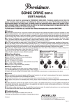
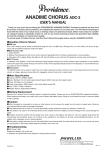
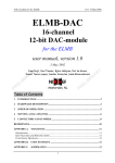
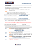
RED ROCK OD ROD-1
OWNER’S MANUAL
Thank you for choosing Providence. In order to take full advantage of the product’s features and performance, please read this manual
thoroughly and keep it in a safe place for future reference.
■Main Features
● Warm overdrive with plenty of sustain gives guitarists a wide-ranging expressive voice. The tone is a perfect match for guitars with single-coil pickups.
● An extra pre-gain circuit and three level controls (VOLUME, GAIN, and MASTER) make it possible to create distortion effects ranging from crunch to hard
drive with subtle control over all nuances in between.
● The pre-gain stage and volume control are similar to guitar amp input circuits, allowing level compensation for pickups of differing output as well as boost
before the signal reaches the overdrive circuit.
● Specially voiced tone control circuitry maintains optimum overdrive sound throughout the control range.
● Internal circuitry doubles the 9-volt supply voltage to 18 volts, achieving wide dynamic range with impressive projection and a sense of unlimited depth.
● In conventional “true bypass” circuits the guitar signal passes through two sets of switch contacts when the effect is bypassed. The ROD-1 features an S.C.T
(Single Contact True-bypass) circuit in which the signal only passes through one set of contacts in bypass mode. This increases reliability while maintaining the
highest possible sound quality at all times.
● Improved output jack grounding is achieved with a D.C.G (Double Contact Ground) circuit that contacts the mono plug ground sleeve at two points rather
than one. Increased ground contact area minimizes intermittent connections while ensuring maximum sonic quality.
■Controls and Connectors
①VOLUME
Adjusts level at the pre-gain stage.
②MASTER
Adjusts the level of the signal output at the OUT jack.
③TONE
Adjusts full-range tonal balance. Turn clockwise to emphasize the midrange and add “edge” to the sound.* Low-frequency compensation is applied at the same time to
prevent the sound from becoming thin.
* Turning this control clockwise also increases overall level. Use the MASTER control to compensate as
necessary.
④GAIN
Adjusts the amount of distortion produced.
⑤FAT
Boosts the low frequency range when engaged. Flip the switch upward to boost the lows.
⑥LED Indicator
Lights when the effect is ON. The LED will start to dim when the battery voltage drops below approximately 7 volts. The effect will still function when the LED begins to dim, but performance may not be optimum
and the battery should be replaced as soon as possible.
⑦IN
The output from a guitar, electronic musical instrument, or preceding effect pedal should be connected
here.
⑧OUT
This jack should be connected to the input of an amplifier or effect unit.
⑨Footswitch
Turns the effect ON or OFF.
⑩DC 9V IN Connector
The DC output from the AC adaptor should be connected here.
Important:
The VOLUME and GAIN controls are designed to provide high maximum gain. When both controls are set
higher than their 12 o’clock (middle) positions saturation will occur and noise may increase. Oscillation may
occur when the maximum settings are approached. For optimum performance, when one of these controls is
set higher than 12 o’clock the other should be set to below 12 o’clock
■Standard Drive
■Classic Hard Drive
■Light Crunch
ON
OFF
MASTER:12 o’clock GAIN:10 o’clock
VOLUME:3 o’clock
TONE:10 o’clock
FAT SWITCH:OFF
OFF
MASTER:12∼3 o’clock GAIN:3 o’clock
MASTER:3 o’clock∼MAX
VOLUME:10 o’clock
VOLUME:11 o’clock∼1 o’clock FAT SWITCH:OFF
TONE:MAX
FAT SWITCH:ON
TONE:1∼2 o’clock
GAIN:MIN
BLOCKDIAGRAM
BUFFER
PRE GAIN
Lo-BOOST
GAIN/
CLIPPER
FILTER
BUFFER
INPUT
OUTPUT
VOLUME
FAT
GAIN
TONE
MASTER
■Specifications
●Controls: VOLUME, MASTER, TONE, GAIN, FAT
●Jacks: Standard 1/4 inch phone jacks (Input/Output), DC9V Input jack (AC adaptor jack)
●Power: 9V battery, AC adaptor
●Power consumption: DC9V approx. 20mA (with effect turned ON)
●Size: 115(D) x 73(W) x 50(H)mm
●Weight: Approx. 250g (without battery installed)
■Battery Replacement
Remove the 4 screws from the back cover to replace the battery. Use a 9V/6F22/MN1604 type replacement battery. When changing the battery, do not pull
strongly on the battery cable. This could result in disconnection or malfunctioning of the device.
■Caution
●When connected to an amp and speaker with the power turned on, do not insert or remove plugs in the input or output jacks. Doing so may cause sufficient
noise to damage the speaker.
●If the pedal should fail to work or if it works abnormally, please contact the place of purchase or Pacifix Ltd.
●If the pedal is not used for an extended period of time, please remove the battery to prevent leakage which could damage the pedal.
●A battery should be inserted into the pedal even when using an AC adaptor. By doing so, if the AC adaptor plug should be inadvertently disconnected, power
will continue to be supplied by the battery to provide uninterrupted performance. An AC adaptor with a regulator circuit is recommended.
●If the battery voltage becomes too low, the pedal effect may become weak, the output level may drop, or no sound may come out of the pedal. In that case,
please replace the battery with a new one.
■Troubleshooting
● If the indicator LED does not light: Replace the battery with a new one or connect an appropriate AC adaptor.
※ (Designs and specifications are subject to change without notice.)
PPD1403-02
Rev 1.0