1
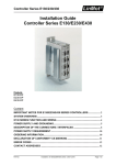
G3 Display/remote 006-00001GF Document rev: 007 Firmware rev: 2.05.06 Date: 08. Feb. 2013 Table of contents IMPORTANT INFORMATION ............................................................................................. 4 Exclusion of liability .................................................................................................................... 4 In the box ...................................................................................................................................... 5 Environment ................................................................................................................................. 5 Mounting ....................................................................................................................................... 5 Cleaning ........................................................................................................................................ 5 Functions ...................................................................................................................................... 5 G3 display outline drawing ......................................................................................................... 6 Start-up Guide .............................................................................................................................. 8 Setting up the basic system ....................................................................................................... 9 Keyboard .................................................................................................................................... 10 Menu and usage ......................................................................................................................... 10 Home screen .............................................................................................................................. 10 Settings and information ........................................................................................................... 12 Menu index ................................................................................................................................. 12 G3 Display Menu Description ................................................................................................... 13 Technical specifications.................................................................................................. 16 G3 Display – General information ............................................................................................ 16 Connectors Pin-out and Location ............................................................................................ 16 G3 display inputs ....................................................................................................................... 17 Output 1 – 3 ................................................................................................................................ 17 Remote output............................................................................................................................ 17 Single wire communication ...................................................................................................... 17 Warranty ..................................................................................................................................... 18 Copyright .................................................................................................................................... 18 G3 Display User Manual IMPORTANT INFORMATION This User-Manual serves a guideline for safe and effective operation, installation of equipment and equipment maintenance. Please read the manual thoroughly before starting installation and operation with the G3 Display. Exclusion of liability Clayton Power shall in no event be liable for any direct or indirect loss, damages or costs arising from use of this Clayton Power product, or in any way connected with faulty installation, improper operation or incorrect utilization and maintenance. Clayton Power shall in no event be liable for any direct or indirect damages, disablement or death on persons who -‐ works with or are dependent on Clayton Power products. -‐ are connected to medical equipment or to any life support system, where Clayton Power products is integrated as a component. Clayton Power Pakhusgården 42 - 48 5000 Odense C Denmark Phone: +45 46 98 57 60 URL: www.claytonpower.com Mail: sales @ claytonpower.com Revision History 2013-01-31: Initial release. 4 G3 Display User Manual In the box 1x G3 display 1x 7-pole data cable (5m) 1x G3 Display manual Environment • • • • The display must be placed in a dry, well ventilated and dust free location. Place the unit within 5 meters of the battery. Make sure that water or dust cannot enter the cabinet. Avoid mounting the device next to flammable materials. Mounting • • • The unit is to be mounted within a casing or mounting hole prepared for the device (4 x Ø4.5mm holes – See G3 outline drawing). Make sure that each wire and connector is connected in according to the set-up guide. During wiring, use standard cable fixtures and connectors. Do not bent the wires extremely and avoid sharp edges to prevent the isolation of the wires from cutting and abrasion. Cleaning • Front can be wiped with a damp cloth for cleaning purposes. Functions G3 Display provides following features: ü Battery voltage measurement ü Remote control of connected G3 unit(s) ü Remote and manual control of generator ü G3 status information ü Display of battery current ü Display of inverter power ü Manual control of Boost charge ü Handles up to six G3 units 5 G3 Display User Manual G3 display outline drawing 6 G3 Display User Manual 7 G3 Display User Manual Start-up Guide Following products are used as reference in this manual: Or G3 Display G3 Inverter/charger G3 Inverter Battery The diagram below shows a basic wiring setup using a G3 Display, 12VDC - 100Ah Lithium Battery and a G3 Combi (Inverter/Charger). Figure 1 Basic system setup 8 G3 Display User Manual Setting up the basic system 1. Connect the white wire to from the G3 Display cable to input 2 in the Lithium Battery using the 5 pin terminal connector. 2. Connect the CP SingleWire between the G3 Display cable, the Lithium Battery and the G3 Inverter/Charger using the green wire from the Display cable and an extra piece of wire (not supplied) between the G3 Inverter/Charger and the Lithium Battery. 3. Connect the power supply and ground (red and black wires) to the battery terminals or an auxiliary 12 V power source. 4. Connect the G3 Display cable to the Lithium Battery and G3 Charger/Inverter. Output 2 and 3 (Purple and Grey wires) are available for output to secondary components such as: LED lights or an alarm system. For a guide on how to setup the outputs for secondary components see Figure 2 For instructions on how to mount and connect battery and G3 inverter or inverter/charger please see G3 and Lithium Battery manual. 9 G3 Display User Manual Keyboard Menu and usage Turn display - The default home screen will appear. Home screen The display has one or three home screens to choose between depending on there being a Lithium battery or Lead battery in the system. In a Lithium system there are three different home screens. In a Lead system only one home screen is available. Lead-acid system: Default home screen 10 G3 Display User Manual Lithium system: Default home screen Press to go home screen 2: Home screen 2 Press to go home screen 3: 11 G3 Display User Manual Settings and information Menu index For any system information and settings enter 1. Display settings 1.1. Output 2 1.1.1. Out 2 Trigger – under voltage 1.1.2. Out 2 Trigger – Over voltage 1.1.3. Out 2 Trigger – Under SOC 1.1.4. Out 2 Trigger – Over SOC 1.1.5. Out 2 Reset – Under voltage 1.1.6. Out 2 Reset – Over voltage 1.1.7. Out 2 Reset – Under SOC 1.1.8. Out 2 Reset – Over SOC 1.1.9. Manual Cont. 1.2. Output 3 1.2.1. Out 3 Trigger – under voltage 1.2.2. Out 3 Trigger – Over voltage 1.2.3. Out 3 Trigger – Under SOC 1.2.4. Out 3 Trigger – Over SOC 1.2.5. Out 3 Reset – Under voltage 1.2.6. Out 3 Reset – Over voltage 1.2.7. Out 3 Reset – Under SOC 1.2.8. Out 3 Reset – Over SOC 1.2.9. Manual Cont. 1.3. Gen-set – Mode 1.4. Temp. Control 1.5. Display Version 2. Lith. Batt. Settings 2.1. Version Lith. Batt. 2.2. View cell voltage 2.3. View temperature 3. Combi xxxx-xx 3.1. Status 3.2. Boost charge 3.3. Firmware 12 , following will appear G3 Display User Manual G3 Display Menu Description Display settings 1.1. Output 2 & 1.2. Output 3 For setting an output from output 2 and/or 3 a trigger threshold and reset threshold has to be made. By default all thresholds are off. It is possible to trigger an output if certain system values get higher or lower than specific a value. The system values are either voltage, starting at 9.00V going to 32V, or State Of Charge (SOC), starting at 1% going to 100%. When the output trigger is set, a reset threshold must also be set in order to deactivate the signal. The reset threshold can be set when the system values get higher or lower than a specific value. The system values are either voltage, starting at 9.00V going to 32V, or State Of Charge, starting at 1% going to 100%. For a manual test of the signal the 1.1.9. / 1.2.9. Manual cont. can be used. Example: Figure 2 Example of using the outputs It is possible to set a trigger that will activate output 2 or 3. With the setup in Figure 2 the G3 Display can activate the Gen-Set if the SOC drops below a predefined level, for example 20%. If the Gen-Set fails, for whatever reason, and the SOC drops below a critical level, for example 10%, output 3 can be activated sounding an alarm that will alert the user of the situation. 13 G3 Display User Manual 1.3. Gen-set – Mode Gen-set mode is mostly used when there is lead–acid batteries in the system. The Gen-set function makes it possible to automatically start a generator when the battery is discharged to a preset voltage, for example 11,5 V, and stop it again when the battery reaches a preset voltage, for example 13,2 V. A timer can also be set to stop the generator. The Gen-set feature is disabled by default. Press to enable gen-set mode. Depending on the Gen-Set interface, Figure 3 shows one way of connecting a Gen-Set to the G3 Display. Figure 3 Gen-Set mode 1.5. Display version Enter to see the current software (SW) and hardware (HW) versions of the G3 display. 14 G3 Display User Manual Lithium battery settings 2.1. Version Lith. Batt. Enter to view firmware vesion of lithium battery. 2.2. View cell voltage Enter to view voltage of all cells. 2.3. View temperature Enter to view temperature of the battery cells. Combi xxxx.xx 3.1. Status Will display Charging if the system is charging or Inverting if the system is in use. 3.2. Boost charge - Only for flooded lead - acid cells. DO NOT USE WITH GEL OR AGM BATTERIES. Press to activate boost charge – Repeat to deactivate During normal charge the Combi charges the battery with a 14.4 voltage, but when boost charge is activated, the Combi raises the charging voltage to 15.4V. The boost charge mode function is automatically disabled when the 230VAC mains grid is removed or the battery is fully charged, making the Combi return to the normal charging voltage. The function is only to be used on flooded lead acid cells periodically to desulfate the cells. This function should not be used on GEL or AGM batteries! 3.3. Firmware Enter to view firmware version of G3 combi. 15 G3 Display User Manual Technical specifications G3 Display – General information G3 Display - General information Operating voltage Absolute Voltage rating Normal mode Consumption (@12VDC) Sleep mode Consumption Operating Temperature Storage Temperature Dimensions Weight Housing 10,2 - 32 VDC 8-35 VDC 70 mA <5 mA -20°C to 55°C -40°C to 55°C 137 x 43,8 x 88 mm 285g Aluminium case Connector J1 Molex 39-28-1123 Connector J4 & J5 Molex 95003-2661 Connectors Pin-out and Location Figure 4: Location of connectors on rear panel of G3 Display J1 Pin Signal Description 1 2 3 4 5 6 7 8 9 10 11 12 GND GND HALL +5V HALL REMOTE OUT +BATTERY DATA OUT_1 OUT_2 OUT_3 SNS HALL INPUT_1 WAKEUP OUT Supply ground ( - BATTERY) Hall sensor ground Hall sensor supply Remote control of G3 Supply voltage (+ BATTERY) Single Wire Data communication Output #1 – Generator remote control Output #2 Output #3 Hall sensor output Input #1 Mating connector type is MOLEX 0039012125 16 G3 Display User Manual J4, J5 Pin 1 2 3 4 5 6 Signal -TEMPX1 GND_TELE +TEMPX1 SYNC_IN/OU T DATA REMOTE OUT Description N/A for Display User’s GND (Fused) N/A for Display N/A for Display Single Wire Data communication Remote control of G3 Mating connector type is MOLEX 0900750031 Connectors J4 and J5 are connected in parallel. G3 display inputs Input pin 1 & 2 Input voltage absolute max “High” level input voltage “Low” level input voltage Input Impedance Transient protection 32 VDC >9 VDC <4 VDC 1.8K By internal diode Output 1 – 3 Output 1 – 3 Output Topology Absolute voltage rating Max sink current Transient protection Open Collector 48 VDC 170 mA By internal diode Remote output Remote Output Source Voltage Max Source Current Output Impedance Transient protection 12 VDC 50 mA 100 Ω By internal diode Single wire communication Single Wire Communication Output Voltage Max source current (limited) Internal pull up resistor Fuse rating Transient protection Communication Topology Communication Speed Communication protocol 12 VDC 450 mA 1K 500mAT By internal diode Simplex USART (0-12v) 9600 baud Clayton Power Single Wire rev2.1D 17 G3 Display User Manual Warranty CAUTION & WARNING: DO NOT USE OR ATTEMPT TO USE THIS PRODUCT UNTIL YOU HAVE READ THIS USER'S MANUAL IN ITS ENTIRETY. IMPROPER INSTALLATION OR USAGE OF THIS DEVICE MAY BE HAZARDOUS AND MAY CAUSE DAMAGE TO OTHER ELECTRICAL EQUIPMENT AND WILL VOID WARRANTY. • Clayton Power warrants, to the original purchaser only, for a period of 24 months from the date of purchase, that the Clayton Power device will be in good working order when properly installed and operated as described in this manual. • If the display fails within this time period under normal use, Clayton Power will, without charge, at the place of Clayton Power's choosing, repair or replace the display - with new or reconditioned parts or a new or reconditioned display as Clayton Power deems necessary. This warranty is void and will not be applied if: • The inverter has been used against the recommendations of this manual. • The inverter has been used in an application outside of general automotive, solar, industrial or marine applications without the agreement of Clayton Power. • The inverter has been modified or repaired without written authorization of Clayton Power. • Reverse polarity, excessive overloading, general abuse, neglect, wear & tear, ingress of liquids (water, oil, acid, or otherwise), foreign objects, lightening strikes, over or under voltage, RFI/EMI, etc. Obtaining Warranty Service To obtain warranty service, please contact the outlet at which you purchased your product. Do not contact Clayton Power directly. For warranty service you will require the following: 1. Proof of purchase 2. Model number 3. Serial number 4. Brief description of application and problem Telephone your Clayton Power dealer for an authorization number prior to dispatch - do not send without authorization. Once this number has been obtained, please carefully package your display and send (freight paid) to the Clayton Power dealer. Copyright The information contained within this document remains the sole property of Clayton Power No part of this document may be copied or reproduced in any form or by any means, and the information contained within is not to be communicated to a third party, without the prior written consent of Clayton Power. 18 G3 Display User Manual CE mark CE-Decla ration of Conformity (€ The following product 006-00001GF G3 Display Fully complies with the guidelines of the directive 2OO4/108/EG, based on the following standards: DIN EN 61204-3:2000 DIN EN 55011:2009 + AL:20L0; DIN EN 55022:2006 + AI:2007; DIN EN 55024:2010 DIN EN 6tOO0-4-2:2009; DIN EN 6L000-4-3:2008; DIN EN 6LOOO-4-4:20L0; DIN EN 61000-4-5:2007; DIN 61000-4-6:2009 Odense, L8.01.2013 Clayton Power ApS 19 EN G3 Display User Manual Clayton Power Pakhusgården 42 – 48 DK-5000 Odense C Denmark Phone: +45 4698 5760 E-mail: sales @ claytonpower.com Web: www.claytonpower.com 20