1
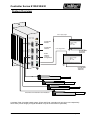
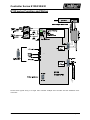
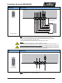
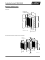
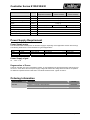
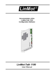
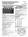
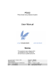
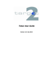
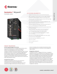
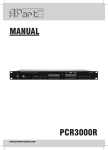
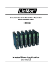
Controller Series E130/230/430 Installation Guide Controller Series E130/E230/E430 Products E130-DP E230-DP E430-DP Content IMPORTANT NOTES FOR E130/E230/E430 SERIES CONTROLLERS ..................... 2 SYSTEM OVERVIEW............................................................................................................. 3 E130 SERIES FUNCTION AND WIRING ........................................................................... 4 POWER SUPPLY AND GROUNDING ................................................................................ 5 DESCRIPTION OF THE CONNECTORS / INTERFACES .............................................. 6 POWER SUPPLY REQUIREMENT ................................................................................... 10 ORDERING INFORMATION ............................................................................................... 10 DECLARATION OF CONFORMITY CE-MARKING ....................................................... 11 ERROR CODES .................................................................................................................... 12 CONTACT ADDRESSES .................................................................................................... 12 NTI AG Installation: E130/E230/E430 series / 28.07.2010 Page 1/12 Controller Series E130/230/430 Important notes for E130/E230/E430 series controllers CAUTION !! In order to assure a safe and error free operation, and to avoid severe damage to system components, all system components must be directly attached to a single ground bus that is earth or utility grounded. Each system component should be tied directly to the ground bus (star pattern), rather than daisy chaining from component to component. (LinMot motors are properly grounded through their power cables when connected to LinMot controllers.) All connectors must not be connected or disconnected while DC voltage is present. Do not disconnect system components until all LinMot controller LED’s have turned off. (Capacitors in the power supply may not fully discharge for several minutes after input voltage been disconnected). Failure to observe these precautions may result in severe damage to electronic components in LinMot motors and/or controllers. Do not switch Power Supply DC Voltage. All power supply switching and E-Stop breaks should be done to the AC supply voltage of the power supply. Do not connect or disconnect the motors from controllers with voltage present. Wait to connect or disconnect motors until all LinMot controller LED’s have turned off. (Capacitors may not fully discharge for several minutes after power has been turned off). Failure to observe these precautions may result in severe damage to electronic components in LinMot motors and/or controllers. © 2010 NTI Ltd This work is protected by copyright. Under the copyright laws, this publication may not be reproduced or transmitted in any form, electronic or mechanical, including photocopying, recording, microfilm, storing in an information retrieval system, not even for didactical use, or translating, in whole or in part, without the prior written consent of NTI AG. LinMot® is a registered trademark of NTI AG. Note The information in this documentation reflects the stage of development at the time of press and is therefore without obligation. NTI AG. reserves itself the right to make changes at any time and without notice to reflect further technical advance or product improvement. NTI AG Installation: E130/E230/E430 series / 28.07.2010 Page 2/12 Controller Series E130/230/430 System Overview Power Supply Signal Fault Ready Stat A Stat B ID High Mot A --> Profibus ID -->--> Mot B --> DP -->--> Mot C --> Com -->--> Mot D --> PWR -->--> 1 6 2 7 3 Profibus DP Address Power Supply Signal 24 ... 48 V 8 4 9 5 ID Low Profibus DP Interface 5 1 6 2 7 3 8 4 9 5 1 6 2 7 3 8 4 9 5 9 4 From AC Mains 1x115V AC 1x230V AC 3 7 2 6 1 RS232 Interface to PC for Configuration 5 9 4 8 3 7 2 6 1 1 6 2 7 3 8 4 9 Power Supply Motor 8 Power Supply Motor 24 ... 48 V 1 2 3 5 From AC Mains 1x115V AC 1x230V AC Linear Motor with internal Position Feedback Complete E430 Controller based system (E130 and E230 controllers will only drive one respectively two motors). Power Supply for Signal and Motor may be the same device (see later). NTI AG Installation: E130/E230/E430 series / 28.07.2010 Page 3/12 Controller Series E130/230/430 E130 series Function and Wiring Picture shows typical wiring of a single axes controller. Multiple axes controller will have additional motor connectors. NTI AG Installation: E130/E230/E430 series / 28.07.2010 Page 4/12 Controller Series E130/230/430 Power Supply and Grounding Power Supply signal Fault Ready Stat A Stat B PWR signal + AC-Mains = - - Circuit Breaker - Fuse GND ID High 1 6 Mot A --> 24...48VDC 2 7 3 8 4 Profibus DP Galvanically Isolated Power Supply: - Switch Mode Power Supply - Transformer with Rectifier Bridge 9 5 -->--> Ground Bus ID Low Mot B --> DP -->--> 1 Mot C --> Com -->--> 1 5 6 2 7 3 8 4 9 5 6 2 7 3 8 4 9 5 9 4 8 3 7 2 6 1 5 9 4 8 3 7 2 6 1 1 Mot D --> PWR -->--> Power Supply motor Emergency Stop Breaker + AC-Mains = - - Circuit Breaker - Fuse 1 6 2 7 3 8 4 2 9 5 3 PWR motor PE GND 24...48VDC Galvanically Isolated Power Supply: - Switch Mode Power Supply - Transformer with Rectifier Bridge All wires 1.5mm2 (AWG16) Instead of two separated power supplies it may be possible to use only one power supply if there is no need to control the signal power supply (logical devices of the controller) and the power supply of the powerstage for the motors independently (see safety rules of the application). In order to assure a safe and error free operation, and to avoid severe damage to system components, all system components must be well grounded to either a single earth or utility ground. This includes both LinMot and all other control system components to the same ground bus. Each system component should be tied directly to the ground bus (star pattern), rather than daisy chaining from component to component. (LinMot motors are properly grounded through their power cables when connected to LinMot controllers.) Power supply connectors must not be connected or disconnected while DC voltage is present. Do not disconnect system components until all LinMot controller LED’s have turned off. (Capacitors in the power supply may not fully discharge for several minutes after input voltage been disconnected).Failure to observe these precautions may result in severe damage to electronic components in LinMot motors and/or controllers. Do not switch Power Supply DC Voltage. All power supply switching and E-Stop breaks should be done to the AC supply voltage of the power supply. Failure to observe these precautions may result in severe damage to controller. NTI AG Installation: E130/E230/E430 series / 28.07.2010 Page 5/12 Controller Series E130/230/430 Description of the connectors / Interfaces Power Supply Power Connector 24...48VDC GND Internal Fuse 500mAT 24...48VDC Internal Fuse 10AT GND internally connected to controller housing 1 PWR Signal+ 2 GND 3 PWR Motor+ 24...48VDC GND PWR Motor + PWR Signal + 1 2 3 24...48VDC Supply GND must be externally connected to earth (Ground Bus) Supply: Supply Voltage 24...48VDC. Absolute max. Rating 48VDC + 10% Supply voltage for PWR Signal and PWR Motor may be different Motor Supply GND must be externally connected to earth Caution: By exceeding 53VDC supply voltage, the controller will go into error state. Voltage higher than 55 VDC will damage the controller! Do not switch Power Supply DC Voltage. All power supply switching and E-Stop breaks should be done to the AC supply voltage of the power supplies Power supply connectors must not be connected or disconnected while DC voltage is present. Wiring: 1.5 mm² (AWG16), max length 5 m LED State Display Fault Ready Stat A Stat B Ready Green READY Stat A Yellow Stat B Yelllow STAT A Coding for the actual operating state STAT B Coding for the actual operating state The display of the various operating states is shown on the last page of this manual. Fault red NTI AG The system has started correctly FAULT An error has occurred (In the state ERROR a blink code of the STAT LEDs A and B tells what the actual error is. The blink codes are explained in chapter ‘Service’of the user Manual.) Installation: E130/E230/E430 series / 28.07.2010 Page 6/12 Controller Series E130/230/430 Motor Connector 2k2 1 6 2 3 7 8 4 9 10k GND GND +5VDC +5VDC GND Mot A (B,C,D) 2k2 Mot A (B,C,D) 5 Temp. Cosine Sine AGND +5VDC Phase 2- Phase 2+ Phase 1- Phase 1+ Outer shield connected to connector housing black green yellow inner shield white grey blue pink red Extension Cable DSUB-9 (female) Note: - Use only special double-shielded Linear Motor Cable (see datasheet ‘extension cables’) - Use +5V (Pin 3) and AGND (Pin 8) only for motor internal Hall Sensor supply (max. 100mA). - Do NOT connect AGND (Pin 8) to ground or earth! - Inner shield (AGND) and outer shield (earth) must be isolated to each other. Caution: - Wrong Motor wiring may damage Linear Motors and/or Servo Controller. - If you are assembling motor cables by your own, double check motor wiring carefully before power up. Do not connect or disconnect the motors from controllers with voltage present. Wait to connect or disconnect motors until all LinMot controller LED’s have turned off. (Capacitors may not fully discharge for several minutes after power has been turned off).Failure to observe these precautions may result in severe damage to electronic components in LinMot motors and/or controllers. Com COM (RS-232) 1k0 GND 5 9 4 8 3 1 7 2 6 6 2 7 3 8 4 9 5 1 RS232: NTI AG RS-232 RX RS-232 TX DSUB-9 (male) GND 9.6kBaud, use 1:1 connection cable to PC Installation: E130/E230/E430 series / 28.07.2010 Page 7/12 Controller Series E130/230/430 DP Profibus Connector DSUB-9 (female) Isolated 5V output: max 50 mA Profibus ID ID High ID Low ID 1 : Profibus address high ID 2 : Profibus address low NTI AG Installation: E130/E230/E430 series / 28.07.2010 Page 8/12 Controller Series E130/230/430 Mechanical Dimension Dimensions Fixings for 2 x M5 screws 119 ® LinMot -E400 Centers 194 210 176 55 Dimensions in mm 70 Recommended mounting for multiple controller installation Fixings for 2 x M5 screws 100 ® LinMot ® LinMot ® LinMot -E400 -E400 -E400 100 50 50 50 100 50 Dimensions in mm NTI AG Installation: E130/E230/E430 series / 28.07.2010 Page 9/12 Controller Series E130/230/430 E130 E230 E430 Single axes controller 2 axes controller 4 axes controller Width mm (in) 70 (2.8) Height mm (in) 210 (8.3) Height without fixings mm (in) 176 (6.9) Depth mm (in) Weight Kg (lb) Case 119 (4.7) 1.1 (2.4) 1.2 (2.7) IP 40 Storage Temperature °C -25…70 Operating Temperature °C 0…50 Max. Case Temperature °C 65 1.3 (2.9) Power Supply Requirement Power Supply motor The calculation of the needed power for the Motor supply is depending on the application and the used motor(s). The following table shows a recommendation for general applications. Controller E100 E200 E400 1 motor Up to 2 motors Up to 4 motors Voltage/ Power 48 V / 150 W 48 V / 300 W 48 V / 300 W LinMot Switched- Power Supply S01-48/150 S01-48/300 S01-48/300 Part-Nr. 0150-1940 0150-1941 0150-1941 Power Supply signal 24 … 48 V / 5 W Regeneration of Power The Exxx controller don’t use a regeneration resistor. In most application the recuperated energy will not become an issue. In cases where the motor power supply voltage will exceeds the voltage limits because of recuperation an additional capacitor between ‘PWR motor’ and ‘GND’ should be used. Typical: 22’000 uF. Ordering Information Servo Controller E130-DP E230-DP E430-DP NTI AG Description Profibus Controller 1 Axis (48V/3A) Profibus Controller 2 Axis (48V/3A) Profibus Controller 4 Axis (48V/3A) Installation: E130/E230/E430 series / 28.07.2010 Art. No. 0150-1621 0150-1622 0150-1624 Page 10/12 Controller Series E130/230/430 Declaration of Conformity CE-Marking Manufacturer: NTI AG LinMot ® Haerdlistrasse 15 8957 Spreitenbach Switzerland Tel.: +41 (0)56 419 91 91 Fax: +41 (0)56 419 91 92 Products: LinMot ® Controllers Type Art.-No. E130-DP 0150-1621 E230-DP 0150-1622 E430-DP 0150-1624 Type Art-No. Type Art.-No. The product must be mounted and used in strict accordance with the installation instruction contained within the User’s Manual, a copy of which may be obtained from NTI Ltd. I declare that as the authorized representative, the above information in relation to the supply/manufacture of this product is in conformity with the stated standards and other related documents in compliance with the protection requirements of the Electromagnetic Compatibility (EMC) Directive 2004/108/EC. Standards Complied with: EMI EN 55011 Class A Electromagnetic EN 61000-4-2 4 kV / 8kV Suspectibility EMC EN 61000-4-4 1 kV / 2kV EN 61000-6-2 EN 61000-4-3 10 V/m EN 61000-4-6 10 V ENV 50204 10 V/m EN 61000-6-4 Company NTI Ltd. Spreitenbach, July 28, 2010 ----------------------------------------------------------R. Rohner / CEO NTI AG NTI AG Installation: E130/E230/E430 series / 28.07.2010 Page 11/12 Controller Series E130/230/430 Error codes Error display When an error occurs it is displayed by means of the blinking of at least one of the four LEDs on the front of the servo controller. Ready LED The Ready LED is ON as soon as the supply voltage for the processor is guaranteed and the system has started up correctly. Communication with the PC over the serial interface is only possible when this LED is ON. The following table summarizes the blink codes and their meaning: F LED Description Fault Stat A Stat B z ~ 3Hz 2x z ~ 1Hz HW system error: Hardware error in the servo controller. off off z ~ 1Hz On SW1 System error: Software error in the servo controller. The system software wasn’t loaded successfully. SW2 System error: Software error in the servo controller. The system software wasn’t loaded successfully. z ~ 2Hz z ~ 2Hz Generic fault: The exact error message may be displayed with the error inspector. 2x z The supply voltage for the Power circuitry is too low. 3x z The supply voltage for the Power circuitry is too high. 4x z The supply voltage for the Signal circuitry is too low. 5x z The supply voltage for the Signal circuitry is too high. 6x z The servo controller is too hot. 8x z Application Software Error (see manual) 1x z The motor is overloaded. 2x z The motor is too hot. 3x z Following error. 4x z The slider is missing from the motor. 6x z The initialization was not completed successfully. 7x z Incorrect motor type configured or damaged motor. 8x z A referenced motion profile for a motor is missing. Selected motion profile not valid for actual drive type. On 1x z: Mot A 2x z: Mot B 3x z: Mot C 4x z: Mot D on LED is ON off LED is OFF z LED blinks shortly (ca. ¼s) LED blinks longer (ca. 1½s) Contact Addresses NTI AG LinMot Haerdlistrasse 15 CH-8957 Spreitenbach Schweiz LinMot Inc. 5750 Townline Road Elkhorn WI 53121 USA NTI AG Tel.: Fax: E-Mail: Web: +41 (0)56-419 91 91 +41 (0)56-419 91 92 [email protected] www.linmot.com Sales: 877-546-3270 262-743-2555 Tech. Service: 877-804-0718 262-743-1284 Fax: 800-463-8708 262-723-6688 E-Mail: [email protected] Web: www.linnmot-usa.com Installation: E130/E230/E430 series / 28.07.2010 Page 12/12