1
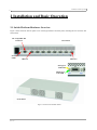
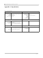
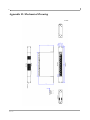
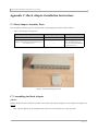
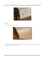
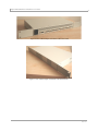
Eight 4X SDR InfiniBand Port Switch Platform
User’s Manual
Part Number: F-X430066
Rev 1.01
2
Eight 4X SDR InfiniBand Port Switch Platform User’s Manual
3
Contents
Contents
3
List of Figures
5
Revision History
7
About this Manual
9
Chapter 1 Overview
11
Chapter 2
Installation and Basic Operation
12
2.1 Switch Platform Hardware Overview
2.1.1 InfiniBand Connectors
2.1.2 InfiniBand Port LEDs
2.1.3 System Status Indicators
2.1.4 I2C-compatible Bus Connector
2.2 Switch Platform Installation and Operation
2.2.1 Mechanical Installation
2.2.2 Power Connections and Initial Power On
2.2.3 InfiniBand Copper Cable Installation
2.2.3.1 Cable Length Support And IB Port Configuration
12
13
13
13
13
13
14
14
14
15
Chapter 3 Management Tools Overview
3.1 Updating Firmware
3.2 IB Administration
3.2.1 IBADM Requirements
3.2.2 How to Get IBADM
16
16
16
17
17
Appendix A Specification
19
Appendix B
Mechanical Drawing
20
Appendix C
Rack Adapter Installation Instructions
21
Rev 1.01
4
Rev 1.01
Eight 4X SDR InfiniBand Port Switch Platform User’s Manual
5
List of Figures
Figure 1:
Figure 2:
Figure 3:
Figure 4:
Figure 5:
Figure 6:
Figure 7:
Switch Front and Rear Panels
Default Configuration Model (Example)
Switch, Mounting Ears, Screws
Rear Panel Side with Ear Screws Removed
Mounting Ear Assembled on Rear Panel Side
View of Rack Adapter Assembled on Rear Panel Sides
View of Rack Adapter Assembled on Front Panel Sides
12
16
21
22
22
23
23
Rev 1.01
6
Rev 1.01
Eight 4X SDR InfiniBand Port Switch Platform User’s Manual
7
Revision History
Table 1 - Revision History Table
Revision & Date
1.01 March 2006
1.00 February 2006
Description
Added warnings to Section 2.2.2, “Power Connections and Initial Power On,” on page 14
First version
Rev 1.01
8
Rev 1.01
Eight 4X SDR InfiniBand Port Switch Platform User’s Manual
9
About this Manual
This manual provides an overview of the Eight 4X SDR InfiniBand Port Switch system and guidelines for its operation. Specifically, it covers the following product:
Table 1 - Switch Products Covered in this User’s Manual
Product Number
Description
F-X430066
Eight 4X InfiniBand Port Switch Platform
Intended Audience
This manual is intended for users and system administrators responsible for installing and setting up the switch platform listed above.
The manual assumes familiarity with the InfiniBand™ architecture specification.
Rev 1.01
10
Rev 1.01
Eight 4X SDR InfiniBand Port Switch Platform User’s Manual
11
1 Overview
This User’s Manual provides an overview of the Eight 4X InfiniBand Port Switch System based on Mellanox Technologies’ MT43132 InfiniScale switch device.
The switch platform comes pre-installed with all necessary firmware and configuration for standard operation in an
InfiniBand fabric running an InfiniBand compliant Subnet Management software in the subnet. All that is required
for normal operation is to follow the usual precautions for installation and connection to the fabric. Once connected,
the Subnet Management software automatically configures and begins utilizing the switch.
Basic installation and hardware maintenance is covered in “Installation and Basic Operation” on page 12.
Maintenance and configuration of the switch is done In-Band through the InfiniBand fabric using the IBADM tools
package. This package provides the ability to monitor the temperature, voltage, port utilization, and other status
parameters in the switch. To upgrade switch firmware, the MFT package is required. See “Management Tools Overview” on page 16.
Rev 1.01
Installation and Basic Operation
12
2 Installation and Basic Operation
2.1 Switch Platform Hardware Overview
Figure 1 shows the front and rear panel views of the Eight 4X Ports Switch System, including the I2C connector and
status LEDs.
I2C-compatible Bus
Connector
Status
LEDs
Rear Panel
IB Port 1
IB Port 8
IB Logical
Link LED
IB Physical
Link LED
Front Panel
Figure 1: Switch Front and Rear Panels
Rev 1.01
Eight 4X SDR InfiniBand Port Switch Platform User’s Manual
13
2.1.1 InfiniBand Connectors
All InfiniBand connectivity is via the rear panel. Figure 1 shows the eight 4X InfiniBand port connectors. Each port
also includes power supply functionality to support fiber media adapters.
2.1.2 InfiniBand Port LEDs
Two IB port LEDs are located to the left of each IB port connector on the rear panel (see Figure 1 on page 12). The
lower (Green) LED is the IB port Physical link LED, and the upper (Yellow) LED is the IB port Logical link LED
(Activity LED).
Physical Link LED (Green) indications:
• Steady On:
The Physical link is established
• Off:
Physical link error, poor connection quality, or no physical connection
Activity LED (Yellow) indications:
• Steady On:
The Logical link is up but there is no data transfer
• Blinking:
Data is being transferred to/from the switch port across the cable wires
• Off:
The Logical link is down
2.1.3 System Status Indicators
Two system status indicators are located on the left of the rear panel and are labeled “Status” (see Figure 1 on
page 12). The following status conditions are possible:
1.
SYSTEM STATUS OK: Green ON, Yellow OFF
2.
TEMPERATURE ALARM: Yellow ON
3.
SYSTEM OFF: Green OFF, Yellow OFF
4.
POWER CIRCUIT ERROR: Green OFF, Yellow OFF (with the power cord connected to power)
2.1.4 I2C-compatible Bus Connector
The I2C-compatible Bus connector is for factory and development use only.
The connector is a female 9 pin D-Type connector. Table 1 shows the pinout functions:
Table 1 - I2C-compatible Bus Connector Pinout Functions
Pin Number
Function
1-5
GND
6
SDA
8
SCL
7, 9
Not Connected
2.2 Switch Platform Installation and Operation
Installation and initialization of the switch platform are straightforward processes, requiring attention to the normal
mechanical, power, and thermal precautions for rack-mounted equipment. The switch platform does not require any
programming or configuration to operate as a basic InfiniBand switch and includes all of the necessary functionality
to operate with external standard InfiniBand Subnet Management software.
Rev 1.01
Installation and Basic Operation
14
This section describes the installation process and basic operation of the switch platform.
2.2.1 Mechanical Installation
The switch platform is packaged in a 1U chassis. See Table 2, “Switch Platform Mechanical and Environmental
Requirements (Worst Case, Fully Populated Chassis)”. If the switch is to be mounted in a standard 19” rack it will
require an adapter. Two ear brackets are included (but not assembled) in the packing box of the switch system, which
can be assembled on the sides of the chassis acting as the 19” rack adapter, and include rack mounting holes which
conform to the IEA-310 standard for such a rack. See “Rack Adapter Installation Instructions” on page 21.
Note:
The installer should use a rack cable to support the mechanical and environmental characteristics of a fully populated switch Chassis as listed in Table 2.
Table 2 - Switch Platform Mechanical and Environmental Requirements (Worst Case, Fully Populated Chassis)
Rack Height
Rack Width
Rack Depth
Weight
Power
Ambient Temp.
1U
12.4”
(315mm)
w/o Rack Adapter
6.9”
(175mm)
7.7lb
(3.5Kg)
45W
Max: 50ºC
Min: 0ºC
19” (EIA-310)
(483mm)
w/ Rack Adapter
Single 100-240 VAC 50-60Hz
Input
Proper ventilation should also be guaranteed for air intake at the front of the chassis and exhaust at the rear in order to
maintain good airflow at ambient temperature. Cable routing in particular should not impede the air exhaust from the
chassis.
Note that the switch platform can be either front or rear mounted. The notion of “front” and “rear” is arbitrary; however, “rear” is used consistently in this manual to refer to the side of the chassis with the InfiniBand connectors.
2.2.2 Power Connections and Initial Power On
Warning: The switch platform will automatically power on when AC power is applied. There is no
power switch. Make sure the power cable is properly plugged into the system before connecting to
power.
Warning: The switch platform must be connected to an earthed mains socket-outlet.
Warning: In Norway, this system should be connected to the IT power distribution system only.
The input voltage is auto-adjusting for a 100-240 VAC, 50-60Hz power connection. The power cord should be a standard 3-wire AC power cord including a safety ground and rated for 2A or higher.
2.2.3 InfiniBand Copper Cable Installation
The switch platform uses industry standard 4X InfiniBand cables which are available from several vendors. The standard 4X cables support full-duplex 10Gb/s wire speed for all switch platform ports. All cables can be inserted or
removed with the unit powered on. To insert a cable, press the connector onto the port receptacle until the connector
is firmly seated. The GREEN LED indicator to the left of each port will light when the physical connection is established (that is, when the unit is powered on and a cable is plugged into the port with a functioning port plugged into
the other end of the connector). After plugging in a cable, lock the connector using the latching mechanism particular
to the cable vendor. To remove, disengage the locks and slowly pull the connector away from the port receptacle.
Both LED indicators will turn off when the cable is unseated.
Rev 1.01
Eight 4X SDR InfiniBand Port Switch Platform User’s Manual
15
Warning:
Care should be taken not to impede the air exhaust flow through the ventilation next to the InfiniBand ports. Cable
lengths should be used which allow for routing horizontally around to the side of the chassis before bending upward
or downward in the rack.
2.2.3.1 Cable Length Support And IB Port Configuration
The switch platform is configured to drive cables up-to 20 meters long. This configuration allows maximum flexibility in building a robust IB cluster.
The selected configuration and cables should meet the required BER specified in the InfiniBand Architecture Specification, Volume 2, release 1.2.
Rev 1.01
Management Tools Overview
16
3 Management Tools Overview
3.1 Updating Firmware
In order to update switch firmware, the MFT tools package is needed by Mellanox Technologies. To download this
package, visit http://www.mellanox.com/support/switch_firmware_table.php. Make sure to also download the MFT
User’s Manual and Release Notes. Specifically, the ‘spark’ tool of the MFT package is required for firmware updates.
Please see the MFT User’s Manual for details.
The most updated firmware is also available for download from the same web page above. Please find the ‘Custom
Switch based on Mellanox's MT43132 InfiniScale switch device’ entry in the firmware table.
3.2 IB Administration
To monitor status conditions in the switch platform, the IBADM tools package is needed (by Mellanox Technologies). IBADM enables the system administrator to manage one or more switch platforms from a single remote InfiniBand host. The features include the following:
• Full In-Band Management of Multiple Switch and HCA Systems from single host1
• Simple default configuration to get started quickly
• Name-based subnet browsing and topology verification
• Event monitoring of port statistics, link status and system status for all ports in the switch
• Checking and updating the firmware
• Intuitive CLI interface
• Extensible and customizable
The figure below shows the default configuration model for these tools:
Figure 2: Default Configuration Model (Example)
Switch Admin Components:
• HCA
• Driver
• IBADM Tools
InfiniBand HCA
One or more switches
InfiniBand
Subnet
w/Subnet
Manager
1. Firmware updates to this Eight 4X IB Port Switch System cannot be performed using ibfwmgr (the burning tool of IBADM package). See Section 3.1, “Updating Firmware,” on page 16.
Rev 1.01
Eight 4X SDR InfiniBand Port Switch Platform User’s Manual
17
3.2.1 IBADM Requirements
The general requirements for installing the IBADM software are listed below. Please see the IBADM release notes
for details on platform, OS, Driver and Subnet Management support.
1.
Computer Platform with an InfiniBand HCA card installed1
2.
HCA Driver
3.
InfiniBand Compliant Subnet Management. The Open Source SM (Eponyms) is supported.
3.2.2 How to Get IBADM
Please visit Mellanox Technologies’s Documents Distribution System at http://docs.mellanox.com. The IBADM
package is available for download under ‘Code Releases/ Tools’. Note that access requires a customer login account.
Consult your sales representative for details.
1. Any Mellanox Technologies HCA card can be used. Consult your sales representative for other possibilities.
Rev 1.01
Management Tools Overview
18
Rev 1.01
Eight 4X SDR InfiniBand Port Switch Platform User’s Manual
19
Appendix A: Specification
Table 3 - Specification Data
Physical
Power and Environmental
Size (HxDxW):
Size with Rack Adapter
Weight:
Mounting:
10Gb/s Connector:
1U x 6.9” x 12.4” (43.6mm x 175mm x 315mm)
1U x 6.9” x 19” (43.6mm x 175mm x 482.6mm)
7.7lb (3.5kg)
19” Rackmount
InfiniBand
Protocol Support
InfiniBand:
QoS:
RDMA Support:
Management:
Input Voltage:
Maximum Power:
Ambient Temperature:
Humidity:
Altitude:
Shock:
Vibration:
Internal Voltage:
100-240 VAC 50-60Hz
45W
0ºC to 50ºC
10% - 90% non-condensing
+5 VDC
Regulatory Compliance
10Gb/s
8 InfiniBand Virtual Lanes for all ports
Yes, All Ports
Performance, and Device management
Agents for full InfiniBand In-Band Management
Scalability and Performance
Switching Performance: Simultaneous wire-speed any port to any port
48K Unicast Addresses Max. per Subnet
Safety
EMC
Reliability, Availability and Serviceability Features
Hot-Swappable: None
N+1 Redundant: None
Addressing: 16K Multicast Addresses per Subnet
Rev 1.01
20
Appendix B: Mechanical Drawing
Rev 1.01
Eight 4X SDR InfiniBand Port Switch Platform User’s Manual
21
Appendix C: Rack Adapter Installation Instructions
C.1 Rack Adapter Assembly Parts
The rack adapter assembly parts are included in the switch packing box and are listed in Table 4:
Table 4 - Rack Adapter Assembly Parts
Item
Quantity
Notes
Mounting Ear
2
See Figure 3
2
Each mounting ear requires 3
screws. Two additional pairs of
screws are to be found assembled on
the switch chassis sides.
Phillips 100° Flat Head, Passivated Stainless Steel
UNC Screw 4-40 x ¼
Figure 3: Switch, Mounting Ears, Screws
C.2 Assembling the Rack Adapter
STEP 1:
Remove the pair of screws from the two sides of the chassis where the rack adapter is to be installed. See Figure 4 on
page 22.
Note: The rack adapter can be installed on the sides close to the front panel or to the rear panel.
Rev 1.01
22
Figure 4: Rear Panel Side with Ear Screws Removed
STEP 2:
Assemble the rack kit as shown in Figure 5.
Figure 5: Mounting Ear Assembled on Rear Panel Side
See also Figure 6,“View of Rack Adapter Assembled on Rear Panel Sides” and Figure 7, “View of Rack Adapter
Assembled on Front Panel Sides,” on page 23.
Rev 1.01
Eight 4X SDR InfiniBand Port Switch Platform User’s Manual
23
Figure 6: View of Rack Adapter Assembled on Rear Panel Sides
Figure 7: View of Rack Adapter Assembled on Front Panel Sides
Rev 1.01
24
Rev 1.01


![*Sted Plus UG Jan 2012 [2].indd](http://vs1.manualzilla.com/store/data/005710511_1-f757ed41a0935df19f469c7cee361c5b-150x150.png)