1
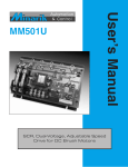
250-0281.qxd 4/4/01 11:16 AM Page a Models: NRGD05-D240AC-4Q NRGD10-D240AC-4Q Digitally-Controlled, Four-Quadrant, Regenerative PWM Drives for DC Brush Motors USER’S MANUAL NRGD–4Q Series 250-0281.qxd 4/4/01 11:16 AM Page b Copyright 2001 by Minarik Corporation All rights reserved. No part of this manual may be reproduced or transmitted in any form without written permission from Minarik Corporation. The information and technical data in this manual are subject to change without notice. Minarik Corporation and its Divisions make no warranty of any kind with respect to this material, including, but not limited to, the implied warranties of its merchantability and fitness for a given purpose. Minarik Corporation and its Divisions assume no responsibility for any errors that may appear in this manual and make no commitment to update or to keep current the information in this manual. Printed in the United States of America. 250-0281.qxd 4/4/01 11:16 AM Page i i Safety Warnings • This symbol denotes an important safety tip or warning. Please read these instructions carefully before performing any of the procedures contained in this manual. • DO NOT INSTALL, REMOVE, OR REWIRE THIS EQUIPMENT WITH POWER APPLIED. Have a qualified electrical technician install, adjust and service this equipment. Follow the National Electrical Code and all other applicable electrical and safety codes, including the provisions of the Occupational Safety and Health Act (OSHA), when installing equipment. • Reduce the chance of an electrical fire, shock, or explosion by proper grounding, over-current protection, thermal protection, and enclosure. Follow sound maintenance procedures. It is possible for a drive to run at full speed as a result of a component failure. Minarik strongly recommends the installation of a master switch in the main power input to stop the drive in an emergency. Circuit potentials are at 120 VAC or 240 VAC above earth ground. Avoid direct contact with the printed circuit board or with circuit elements to prevent the risk of serious injury or fatality. Use a non-metallic screwdriver for adjusting the calibration trimpots. Use approved personal protective equipment and insulated tools if working on this drive with power applied. 250-0281.qxd 4/4/01 11:16 AM Page ii ii Contents Specifications 1 Dimensions 3 Installation 6 Mounting . . . . . . . . . . . . . . . . . . . . . . . . . . . . . . . . . . . . . . . . . . . . . . . . . . . . .6 Wiring . . . . . . . . . . . . . . . . . . . . . . . . . . . . . . . . . . . . . . . . . . . . . . . . . . . . . . .7 Shielding guidelines . . . . . . . . . . . . . . . . . . . . . . . . . . . . . . . . . . . . . . . . . .8 Heat sinking . . . . . . . . . . . . . . . . . . . . . . . . . . . . . . . . . . . . . . . . . . . . . . . . . .9 Line fusing . . . . . . . . . . . . . . . . . . . . . . . . . . . . . . . . . . . . . . . . . . . . . . . . . .10 Speed adjust potentiometer installation . . . . . . . . . . . . . . . . . . . . . . . . . . . . .11 Connections . . . . . . . . . . . . . . . . . . . . . . . . . . . . . . . . . . . . . . . . . . . . . . . . .12 Power, fuse and motor connections . . . . . . . . . . . . . . . . . . . . . . . . . . . . .12 Optional switch connections . . . . . . . . . . . . . . . . . . . . . . . . . . . . . . . . . . .15 Optional speed adjust potentiometer connections . . . . . . . . . . . . . . . . . . .18 Regen dump circuit connections . . . . . . . . . . . . . . . . . . . . . . . . . . . . . . . .20 Voltage signal follower connections . . . . . . . . . . . . . . . . . . . . . . . . . . . . .22 Jumper settings . . . . . . . . . . . . . . . . . . . . . . . . . . . . . . . . . . . . . . . . . . . . . . .23 Tach-generator feedback voltage select (J501) . . . . . . . . . . . . . . . . . . . . .23 Feedback select (J502/J503) . . . . . . . . . . . . . . . . . . . . . . . . . . . . . . . . . .23 Motor armature voltage select (J505/J506) . . . . . . . . . . . . . . . . . . . . . . . .24 Operation 28 Before applying power: . . . . . . . . . . . . . . . . . . . . . . . . . . . . . . . . . . . . . . . . .28 Startup and shutdown . . . . . . . . . . . . . . . . . . . . . . . . . . . . . . . . . . . . . . . . . .29 Starting and stopping methods . . . . . . . . . . . . . . . . . . . . . . . . . . . . . . . . . . .30 Calibration 32 NRGD05 Series Calibration Trimpots . . . . . . . . . . . . . . . . . . . . . . . . . . . . . . .33 NRGD10 Series Calibration Trimpots . . . . . . . . . . . . . . . . . . . . . . . . . . . . . . .34 250-0281.qxd 4/4/01 11:16 AM Page iii iii Calibration procedure . . . . . . . . . . . . . . . . . . . . . . . . . . . . . . . . . . . . . . . . . .35 Before applying power . . . . . . . . . . . . . . . . . . . . . . . . . . . . . . . . . . . . . . .35 Application Notes Connection to other Minarik devices . . . . . . . . . . . . . . . . . . . . . . . . . . DIRECTION switch . . . . . . . . . . . . . . . . . . . . . . . . . . . . . . . . . . . . . . . FWD-STOP-REV switch . . . . . . . . . . . . . . . . . . . . . . . . . . . . . . . . . . . Independent adjustable speeds . . . . . . . . . . . . . . . . . . . . . . . . . . . . . Independent forward and reverse speeds . . . . . . . . . . . . . . . . . . . . . . Independent forward and reverse speeds with FWD-STOP-REV switch Troubleshooting Before applying power Diagnostic LEDs . . . . Terminal assignments Replacement Parts . . Index Unconditional Warranty . .. . .. . . . . . . . . . . . . . . . . . . . . . . . . . . . . . . . . . . . . . . . . . . . . . . . . . . . . . . . . . . . . . . . . . . . . . . . . . . . . . . . . . . . . . . . . . . . . . . . . . . . . . . . . . . . . . . . . . . . . . . . . . . . . . . . . . . . . . . . . . . . . . . . . . . . . . . . . . . . . . . . . . . . 45 .45 .46 .47 .48 .49 .50 . . . . . . . . . . . . . . . . 51 .51 .52 .54 .60 62 inside back cover 250-0281.qxd 4/4/01 11:16 AM Page iv iv Illustrations Figure 1. Four Quadrant Operation . . . . . . . . . . . . . . . . . . . . . . . . . . . . . . . .vii Figure 2. NRGD05 Series Dimensions . . . . . . . . . . . . . . . . . . . . . . . . . . . . . .3 Figure 3. NRGD10 Series Dimensions . . . . . . . . . . . . . . . . . . . . . . . . . . . . . .4 Figure 4. Heat Sink Dimensions for NRGD10 Series Drives . . . . . . . . . . . . . .5 Figure 4. Speed Adjust Potentiometer . . . . . . . . . . . . . . . . . . . . . . . . . . . . .11 Figure 5. Power and Motor Connections . . . . . . . . . . . . . . . . . . . . . . . . . . .14 Figure 6. Signal and Optional Switch Connections . . . . . . . . . . . . . . . . . . . .17 Figure 7. Speed Adjust Potentiometer Connections Figure 8. Regen Dump Circuit Connections To NRGD Drives . . . . . . . . . . . .21 Figure 9. Voltage Follower Connections . . . . . . . . . . . . . . . . . . . . . . . . . . . .22 . . . . . . . . . . . . . . . . . .19 Figure 10. NRGD05 Jumper Terminal Location . . . . . . . . . . . . . . . . . . . . . . .25 Figure 11. NRGD10 Jumper Terminal Location . . . . . . . . . . . . . . . . . . . . . . .26 Figure 12. Jumper Settings . . . . . . . . . . . . . . . . . . . . . . . . . . . . . . . . . . . . . .27 Figure 13. NRGD05 Calibration Trimpot Layout . . . . . . . . . . . . . . . . . . . . . .33 Figure 14. NRGD10 Calibration Trimpot Layout . . . . . . . . . . . . . . . . . . . . . .34 Figure 15. Connection to DLC600 and PCM4 . . . . . . . . . . . . . . . . . . . . . . . .45 Figure 16. Direction Switch . . . . . . . . . . . . . . . . . . . . . . . . . . . . . . . . . . . . . .46 Figure 17. Forward-Stop-Reverse Switch . . . . . . . . . . . . . . . . . . . . . . . . . . . .47 Figure 18. Independent Adjustable Speeds . . . . . . . . . . . . . . . . . . . . . . . . . .48 Figure 19. Independent Forward and Reverse Speeds . . . . . . . . . . . . . . . . . .49 Figure 20. Independent Forward and Reverse Speeds with a Forward-Stop-Reverse Switch . . . . . . . . . . . . . . . . . . . . . . .50 Figure 21. NRGD05 Diagnostic LED Location . . . . . . . . . . . . . . . . . . . . . . . .53 Figure 22. NRGD10 Diagnostic LED Location . . . . . . . . . . . . . . . . . . . . . . .53s 250-0281.qxd 4/4/01 11:16 AM Page v v Tables Table 1. Recommended Line Fuse Sizes . . . . . . . . . . . . . . . . . . . . . . . . . .10 Table 2. Regen Dump Circuit Part Numbers Table 3. Replacement Parts . . . . . . . . . . . . . . . . . . . . . . .20 . . . . . . . . . . . . . . . . . . . . . . . . . . . . . . . . . . .60 250-0281.qxd 4/4/01 11:16 AM Page vi vi Regenerative Drives Non-regenerative, variable speed DC drives control current and speed to a motor in one direction only. The direction of current flow is in the same direction as the motor rotation. This is commonly described as Single Quadrant operation. (Quadrants 1 or 3 depending on your direction of rotation-see Figure 1). Non-regenerative drives cannot oppose an overhauling load with reverse torque, nor decelerate a load faster than coasting to a lower speed. Dynamic braking with an external brake resistor can be added to accomplish these things; however, it would require the use of an external switch. Regenerative drives, however, can operate in all four quadrants of operation. They are able to control motor speed and current in both directions simultaneously. Thus, regenerative drives can reverse a motor, oppose an overhauling load and decelerate a load faster than it would take to coast to a lower speed–all without any external contactors or switches. 250-0281.qxd 4/4/01 11:16 AM Page vii Regenerative Drives Figure 1. Four Quadrant Operation vii 250-0281.qxd 4/4/01 11:16 AM Page viii viii NRGD–4Q Drives Minarik’s NRGD–4Q Series drives are four-quadrant, full-wave, regenerative PWM drives. These open-chassis drives come with the following features: Low power consumption. The NRGD series consume 30% less power than typical analog PWM drives, and 50% less power than typical SCR drives. Four-quadrant ACCEL/DECEL. The ACCEL trimpot determines the time the motor takes to ramp from a lower to a higher speed independent of direction. The DECEL trimpot determines the time the motor takes to ramp down from higher to lower speed independent of direction. Pulse width modulation. Lower form factor than SCR drives (1.10 versus 1.37) throughout the motor speed range. Motor runs with greater efficiency and less maintenance. Four-quadrant regenerative operation. See Regenerative drives section on the preceding pages. Regenerative braking. When used with an external dump circuit, the drive brakes along user-adjusted deceleration profile. No contactors required and no electromechanical components to overheat or wear out. 250-0281.qxd 4/4/01 11:16 AM Page ix NRGD-4Q Drives Fast brake/inhibit. Active braking as fast as user-adjusted current limit allows. Enable/Disable. Turns off the output stage, allowing the motor to coast to a stop. Cage-clamp terminals. Quicker and easier wiring than screw terminals. Plug reversing. Quickly switch from forward to reverse without contactors. Autoranging dual voltage input Power the drive with either 120 VAC or 240 VAC. Tachogenerator feedback option. Improve the speed regulation from approximately 1% (armature feedback) to 0.1% with tachogenerator feedback. Diagnostic LEDs. Green POWER ON and red FAULT LEDs allow easy visual inspection of the drive status. User adjustable trimpots. Calibrate the drive precisely to your application needs with the nine trimpots described in the Calibration section (starting on page 31). ix 250-0281.qxd x Notes 4/4/01 11:16 AM Page x 250-0281.qxd 4/4/01 11:16 AM Page 1 1 Specifications NRGD05-D240AC-4Q Maximum Continuous Armature Current 5.0 amps DC Peak Armature Current* 7.5 amps DC HP Range (120 VAC Line Voltage) 1/8 – 1/2 HP Range (240 VAC Line Voltage) 1/4 – 1 NRGD10-D240AC-4Q Maximum Continuous Armature Current – No Heat Sink 5.0 amps DC Maximum Continuous Armature Current with Heat Sink Installed** 10.0 amps DC Peak Armature Current* 15 amps DC HP Range (120 VAC Line Voltage) 1/4 – 1 HP Range (240 VAC Line Voltage) 1/2 – 2 *Applied for less than one minute. **NRGD10 series drives require heat sink kit 223-0363 when continuous armature current is above 5 ADC. AC Line Voltage 120 VAC or 240 VAC, ±10%, 50Hz or 60 Hz, single phase Armature Voltage Range 120 VAC line voltage 0 – 130 VDC 240 VAC line voltage 0 – 240 VDC Form Factor 1.10 Acceleration Time Range 0.1 – 20 seconds Deceleration Time Range 0.1 – 20 seconds Floating Input Signal Range (signal must be isolated) – 10 to +10 VDC 250-0281.qxd 2 4/4/01 11:16 AM Page 2 Specifications Input Impedance 100K ohms minimum Speed Regulation (% of base speed) 1% open loop 0.1% in tachogenerator feedback mode Vibration 0.5G max. (0–50 Hz); 0.1G max. (>50 Hz) Weight Ambient Operating Temperature Range† † Forced external air flow is required to meet temperature limits 0.78 lb 10° C – 40° C 250-0281.qxd 4/4/01 11:16 AM Page 3 3 Dimensions ALL DIMENSIONS IN INCHES [MILLIMETERS] Figure 2. NRGD05 Series Dimensions 250-0281.qxd 4 4/4/01 11:16 AM Page 4 Dimensions ALL DIMENSIONS IN INCHES [MILLIMETERS] Figure 3. NRGD10 Series Dimensions 250-0281.qxd 4/4/01 11:16 AM Page 5 Dimensions Figure 4. Heat Sink Dimensions for NRGD10 Series Drives 5 250-0281.qxd 4/4/01 11:16 AM Page 6 6 Installation Mounting Warning Do not install, rewire, or remove this control with line voltage applied. Doing so may cause fire or serious injury. Make sure you have read and understood the Safety Warnings before attempting installation. • Drive components are sensitive to electrostatic fields. Avoid direct contact with the circuit board. Hold drive by the chassis only. • Protect the drive from dirt, moisture, and accidental contact. Provide sufficient room for access to the terminal block and calibration trimpots. • Mount the drive away from heat sources. Operate the drive within the specified ambient operating temperature range. • Prevent loose connections by avoiding excessive vibration of the drive. • Mount drive with its board in either a horizontal or vertical plane. Six 0.19 in. (5 mm) wide slots in the chassis accept #8 pan head screws. Fasten either the large base or the narrow flange of the chassis to the subplate. • The chassis must be earth grounded. Use a star washer beneath the head of at least one of the mounting screws to penetrate the anodized chassis surface and to reach bare metal. 250-0281.qxd 4/4/01 11:16 AM Page 7 Installation Wiring Warning Do not install, remove, or rewire this equipment with power applied. Failure to heed this warning may result in fire, explosion, or serious injury. Circuit potentials are at 120 or 240 VAC above ground. To prevent the risk of injury or fatality, avoid direct contact with the printed circuit board or with circuit elements. Do not disconnect any of the motor leads from the drive unless power is removed or the drive is disabled. Opening any one motor lead may destroy the drive. • Use 18-24 AWG wire for speed adjust potentiometer wiring. Use 14–16 AWG wire for AC line (L1, L2) and motor (A1, A2) wiring. 7 250-0281.qxd 8 4/4/01 11:16 AM Page 8 Installation Shielding guidelines Warning Under no circumstances should power and logic leads be bundled together. Induced voltages can cause unpredictable behavior in any electronic device, including motor controls. As a general rule, Minarik recommends shielding of all conductors. If it is not practical to shield power conductors, Minarik recommends shielding all logic-level leads. If shielding is not practical, the user should twist all logic leads with themselves to minimize induced noise. It may be necessary to earth ground the shielded cable. If noise is produced by devices other than the drive, ground the shield at the drive end. If noise is generated by a device on the drive, ground the shield at the end away from the drive. Do not ground both ends of the shield. If the drive continues to pick up noise after grounding the shield, it may be necessary to add AC line filtering devices, or to mount the drive in a less noisy environment. Logic wires from other input devices, such as motion controllers and PLC velocity controllers, must be separated from power lines in the same manner as the logic I/O on this drive. 250-0281.qxd 4/4/01 11:16 AM Page 9 Installation 9 Heat sinking NRGD05-series drives do not require an external heat sink. NRGD10-series drives require an external heat sink kit, part number 223-0363, when the continuous armature current is above 5 amps DC. Apply a thermally conductive heat sink compound (such as Dow Corning® 340 Heat Sink Compound) in a thin layer between the drive chassis and heat sink surface for optimum heat transfer. 250-0281.qxd 10 4/4/01 11:16 AM Page 10 Installation Line fusing Protect all Minarik drives with AC line fuses. Use fast acting AC line fuses rated for 250 volts, and approximately 150% – 200% of the maximum armature current. Fuse only the “hot” side of the AC line (L1) if using 120 VAC line voltage. See Table 1 below for recommended line fuse sizes. Table 1. Recommended Line Fuse Sizes 90 VDC Motor 180 VDC Motor Horsepower Horsepower 1/20 1/10 1/15 1/8 1/8 1/4 1/6 1/3 1/4 1/2 1/3 3/4 1/2 1 3/4 1 1/2 1 2 Max. DC Armature AC Line Current (amps) Size (amps) 0.5 2 0.8 2 1.5 3 1.7 5 2.5 8 3.5 8 5.0 10 7.5 15 10 20 Minarik Corporation offers two fuse kits: part number 050–0069 (3–8A Fuse Kit) and 050–0073 (5–20A Fuse Kit). 250-0281.qxd 4/4/01 11:16 AM Page 11 Installation 11 Speed adjust potentiometer installation Warning Be sure that the potentiometer tabs do not make contact with the potentiometer enclosure. Grounding the input will cause damage to the drive. Mount the speed adjust potentiometer through a 0.38 in. (10 mm) hole with the hardware provided (Figure 4). Install the circular insulating disk between the panel and the 10K ohm speed adjust potentiometer. Twist the speed adjust potentiometer wire to avoid picking up unwanted electrical noise. If speed adjust potentiometer wires are longer than 18 in. (457 mm), use shielded cable. Keep speed adjust potentiometer wires separate from power leads (L1, L2, A1, A2). Figure 4. Speed Adjust Potentiometer 250-0281.qxd 12 4/4/01 11:16 AM Page 12 Installation Connections Warning Do not install, remove, or rewire this equipment with power applied. Failure to follow this warning may result in fire, explosion, or serious injury. Minarik strongly recommends the installation of a master power switch in the voltage input line, as shown in Figure 5, page 14. The switch contacts should be rated at a minimum of 200% of motor nameplate current and 250 volts. Power, fuse and motor connections Connect the power input leads, an external line fuse and a DC motor to TB501 on the drive’s printed circuit board (PCB) as shown in Figure 5, page 14. Motor Minarik drives supply motor voltage from A1 and A2 terminals. It is assumed throughout this manual that, when A1 is positive with respect to A2 , the motor will rotate clockwise (CW) while looking at the output shaft protruding from the front of the motor. If this is opposite of the desired rotation, simply reverse the wiring of A1 and A2 with each other. 250-0281.qxd 4/4/01 11:16 AM Page 13 Installation 13 With line voltage disconnected, connect a DC motor armature to PCB terminals A1 and A2 as shown in Figure 5. Ensure that the motor voltage rating is consistent with the drive’s output voltage. Power input Warning Do not install, remove, or rewire this equipment with power applied. Failure to follow this warning may result in fire, explosion, or serious injury. Minarik strongly recommends the installation of a master power switch in the voltage input line, as shown in Figure 5, page 14. The switch contacts should be rated at a minimum of 200% of motor nameplate current and 250 volts. Connect the AC line power leads to TB501 terminals L1 and L2, or to a single-throw, double-pole master power switch (recommended). Line fuse With line voltage disconnected, wire an external line fuse between the stop switch (if installed) and the L1 terminal on terminal board TB501. An additional line fuse should be installed on L2 if the input voltage is 240 VAC. The line fuse(s) should be rated at 250 volts and 150 - 200% of maximum motor nameplate current. Refer to the line fuse chart on page 10 for fuse ratings. 250-0281.qxd 14 4/4/01 11:16 AM Page 14 Installation TO REGEN DUMP CIRCUIT BUS+ AND BUSTERMINALS (OPTIONAL); SEE PAGE 20 NOTE: INSTALL FUSE ON L2 WHEN LINE VOLTAGE IS 240 VAC. DO NOT INSTALL IF LINE VOLTAGE IS 120 VAC. Figure 5. Power and Motor Connections 250-0281.qxd 4/4/01 11:16 AM Page 15 Installation 15 Optional switch connections Connect the following switches or jumpers to terminal board TB502 as shown in Figure 6, page 17. ENABLE/DISABLE switch Install a single-pole, single-throw switch between the ENABLE and COM terminals. Open the switch to disable the drive and coast the motor to a stop. Close the switch to enable the drive and run the motor. If no switch is installed, a jumper must be installed for the drive to run. RUN/BRAKE switch Install a single-pole, single-throw switch between the RB and COM terminals. Close the switch to regeneratively brake the motor to minimum speed at a rate controlled by the DECEL trimpot. Open the switch to accelerate the motor to set speed at a rate controlled by the ACCEL trimpot. Direction switch Install a single-pole, single-throw switch between the DIR and COM terminals. Close the switch to change direction. Refer to the Application Notes for additional direction switch connections. 250-0281.qxd 16 4/4/01 11:16 AM Page 16 Installation INHIBIT switch Shorting the INH and COM terminals on connector TB502 to each other causes the motor to regeneratively brake the motor to a stop at the maximum current allowed by the CURRENT LIMIT trimpot setting, bypassing the DECEL trimpot circuit. Remove the short to accelerate the motor to set speed. An alternative is to install a single-pole, single- throw switch between the INH and COM terminals. Close the switch to decelerate to a stop. Open the switch to accelerate the motor to set speed. 250-0281.qxd 4/4/01 11:16 AM Page 17 Installation NOTE: REFER TO FIGURE 7 (PAGE 19) FOR ADDITIONAL SPEED ADJUST POTENTIOMETER CONNECTIONS Figure 6. Signal and Optional Switch Connections 17 250-0281.qxd 18 4/4/01 11:16 AM Page 18 Installation Optional speed adjust potentiometer connections The motor can operate in one direction (unidirectionally) or two directions (bidirectionally) depending on how the speed adjust potentiometer is connected to the drive. Connect the speed adjust potentiometer as shown in Figure 7a for bidirectional operation. The motor shaft does not rotate when the wiper is in the center position. Turning the wiper CW from the center causes the motor to rotate in one direction, while turning the wiper CCW from center causes rotation in the opposite direction. Connect the speed adjust potentiometer as shown in Figure 7b for unidirectional operation in the forward direction. Connect the speed adjust potentiometer as shown in Figure 7c for unidirectional operation in the reverse direction. Refer to the Application Notes for additional speed adjust potentiometer connections. 250-0281.qxd 4/4/01 11:16 AM Page 19 Installation 19 (a) (b) (c) Figure 7. Speed Adjust Potentiometer Connections for (a) Bidirectional Operation; (b) Unidirectional Operation (Forward); and (c) Unidirectional Operation (Reverse) 250-0281.qxd 20 4/4/01 11:16 AM Page 20 Installation Regen dump circuit connections Warning Minarik strongly recommends the installation of an extenal regen dump circuit if you plan to use regenerative braking. This will help avoid damage to the motor or drive. The external regen dump circuit reduces the voltage across the bus capacitor when it reaches a factory-set trip point. As the drive regeneratively brakes, it returns excess voltage to the bus capacitor, where it is stored until it can be discharged. When the regen dump circuit detects excess bus voltage, it redirects or “dumps” the excess voltage through a shunt resistor network, safely discharging the bus capacitor. Bus capacitor maximum working voltage ratings are 200 VDC for 120 VAC drives and 400 VDC for 240 VAC drives. Please contact your Minarik representative for more information on changing the dump circuit’s regen dump trip setting. Refer to Figure 8, page 21, for regen dump circuit connections. Table 2. Regen Dump Circuit Part Numbers Drive model number NRGDxx–D240AC–4Q NRGD Drive Line Input Voltage 120 VAC 240 VAC BOSS DB-115* BOSS DB-230* *Because the BOSS-DB is powered by the drive’s bus voltage, the BOSS DB-230 regen dump circuit requires a line voltage of 240 VAC. Use BOSS DB-115 if line voltage is 120 VAC. 250-0281.qxd 4/4/01 11:16 AM Page 21 Installation Figure 8. Regen Dump Circuit Connections To NRGD Drives 21 250-0281.qxd 22 4/4/01 11:16 AM Page 22 Installation Voltage signal follower connections Instead of using a speed adjust potentiometer to set motor speed, the drive may follow a floating (isolated) –10 to +10 VDC signal. Connect the signal input (+) to S2, and signal common (-) to S0. See Figure 9. Figure 9. Voltage Follower Connections 250-0281.qxd 4/4/01 11:16 AM Page 23 Installation 23 Jumper settings Warning Do not change jumper settings with power applied. Remove line voltage or disable the drive before changing jumper settings. Failure to follow these instructions may result in damage to the drive or motor or serious injury. For NRGD05-series jumper locations, refer to Figure 10 (page 25). For NRGD10-series jumper locations, refer to Figure 11 (page 26). Tach-generator feedback voltage select (J501) NOTE: This jumper setting is applicable only if J502 and J503 are set for tach-generator feedback. It is otherwise inoperative. Jumper terminals 1 and 2 on J501 as shown if the tach-generator voltage range is 7.5–20 volts/1000 RPM. Jumper terminals 2 and 3 if the voltage range is 50–100 volts/1000 RPM. The factory (default) setting is 7.5–20 volts/1000 RPM (terminals 1 and 2). See Figure 12, page 27, for settings. Feedback select (J502/J503) Jumper terminals 1 and 2 on J502 and J503 as shown if the feedback selected is from the motor armature. Jumper terminals 2 and 3 on J502 and J503 if the feedback is from a tach-generator. The factory (default) setting is motor armature feedback (terminals 1 and 2). See Figure 12, page 27, for settings. 250-0281.qxd 24 4/4/01 11:16 AM Page 24 Installation Motor armature voltage select (J505/J506) Jumper terminals 1 and 2 on J505 and J506 if the motor armature voltage is 90 volts. Jumper terminals 2 and 3 on J505 and J506 if the motor armature voltage is 180 volts. The factory (default) setting is 180 volts (terminals 2 and 3). See Figure 12, page 27, for settings. 250-0281.qxd 4/4/01 11:16 AM Page 25 Installation 25 ARMATURE VOLTAGE SELECT (J505 AND J506) ARM/TACH FEEDBACK SELECT (J502 AND J503) TACH VOLTAGE RANGE SELECT (J501) Figure 10. NRGD05 Jumper Terminal Location 250-0281.qxd 26 4/4/01 11:16 AM Page 26 Installation ARMATURE VOLTAGE SELECT (J505 AND J506) TACH VOLTAGE RANGE SELECT (J501) ARM/TACH FEEDBACK SELECT (J502 AND J503) Figure 11. NRGD10 Jumper Terminal Location 250-0281.qxd 4/4/01 11:16 AM Page 27 Installation J502/J503 ARM/TACH FEEDBACK SELECT J505/J506 MOTOR ARMATURE VOLTAGE J501 TACH FEEDBACK VOLTAGE RANGE Figure 12. Jumper Settings 27 250-0281.qxd 4/4/01 11:16 AM Page 28 28 Operation Warning Dangerous voltages exist on the drive when it is powered, and up to 30 seconds after power is removed and the motor stops. BE ALERT. High voltages can cause serious or fatal injury. For your safety, use personal protective equipment (PPE) when operating this drive. Do not change jumper settings with power applied. Remove line voltage or disable the drive before changing jumper settings. Failure to follow these instructions may result in damage to the drive or motor or serious injury. Before applying power: • Verify that no conductive material is present on the printed circuit board. • Ensure that all jumpers are properly set. 250-0281.qxd 4/4/01 11:16 AM Page 29 Operation 29 Startup and shutdown To start the drive: 1. Turn the speed adjust potentiometer full counterclockwise (CCW). If the speed adjust potentiometer is wired for bidirectional operation, set the pot to its center of travel. If the drive is following a voltage signal, set the voltage signal to 0 VDC. 2. Apply AC line voltage. 3. Slowly advance the speed adjust potentiometer clockwise (CW). If the drive is following a voltage signal, slowly increase the voltage signal. The motor slowly accelerates as the potentiometer is turned CW, or the voltage signal is increased. Continue until the desired speed is reached. 4. Remove AC line voltage from the drive to coast the motor to a stop. If the motor or drive does not perform as described, disconnect the AC line voltage immediately. Refer to the Troubleshooting section for further assistance. 250-0281.qxd 30 4/4/01 11:16 AM Page 30 Operation Starting and stopping methods Warning Decelerating to minimum speed, regenerative braking, or coasting to a stop is recommended for frequent starts and stops. Do not use any of these methods for emergency stopping. They may not stop a drive that is malfunctioning. Removing AC line power (both L1 and L2) is the only acceptable method for emergency stopping. For this reason, Minarik strongly recommends installing an emergency stop switch on both the L1 and L2 inputs (see Figure 5, page 14). Frequent decelerating to minimum speed or regenerative braking produces high torque. This may cause damage to motors, especially gearmotors that are not properly sized for the application. Minarik strongly recommends the installation of an external regen dump circuit if you plan to use the NRGD’s regenerative braking capability. This will help avoid damage to the motor and/or drive. Refer to page 20 for information on connecting an external regen dump circuit. Automatic restart upon power restoration After a one-second time delay, all drives automatically run to set speed when power is applied and the ENABLE input is jumpered. 250-0281.qxd 4/4/01 11:16 AM Page 31 Operation 31 INHIBIT switch Shorting the INH and COM terminals on connector TB502 to each other causes the motor to regeneratively brake the motor to a stop at a rate controlled by the CURRENT LIMIT trimpot, bypassing the DECEL trimpot circuit. Remove the short to accelerate the motor to set speed. See Figure 6, page 17. An alternative is to install a single-pole, single- throw switch between the INH and COM terminals. Close the switch to decelerate to minimum speed at a rate controlled by the CURRENT LIMIT trimpot. Open the switch to accelerate the motor to set speed. ENABLE/DISABLE switch Install a single-pole, single-throw switch between the ENABLE and COM terminals. Open the switch to disable the drive and coast the motor to a stop. Close the switch to enable the drive and run the motor. If no switch is installed, a jumper must be installed for the drive to run. See Figure 6, page 17. RUN/BRAKE switch Install a single-pole, single-throw switch between the RB and COM terminals. Close the switch to regeneratively brake the motor to minimum speed at a rate controlled by the DECEL trimpot. Open the switch to accelerate the motor to set speed at a rate controlled by the ACCEL trimpot. See Figure 6, page 17. 250-0281.qxd 4/4/01 11:16 AM Page 32 32 Calibration Warning Dangerous voltages exist on the drive when it is powered, and up to 30 seconds after power is removed and the motor stops. When possible, disconnect the voltage input from the drive before adjusting the trimpots. If the trimpots must be adjusted with power applied, use insulated tools and the appropriate personal protection equipment. BE ALERT. High voltages can cause serious or fatal injury. NRGD–4Q drives have nine user-adjustable trimpots. Each drive is factory calibrated to its maximum horsepower rating. Readjust the calibration trimpot settings to accommodate lower horsepower motors. With the exception of the TACH trimpot, all adjustments increase with CW rotation, and decrease with CCW rotation. The TACH trimpot increases with CCW rotation, and decreases with CW rotation. Use a non-metallic screwdriver for calibration. Each trimpot is identified on the printed circuit board. 250-0281.qxd 4/4/01 11:16 AM Page 33 Calibration 33 NRGD05 Series Calibration Trimpots TACHOGENERATOR BALANCE MAXIMUM SPEED ACCELERATION LOOP CURRENT LIMIT IR COMP OFFSET DECELERATION Figure 13. NRGD05 Calibration Trimpot Layout 250-0281.qxd 34 4/4/01 11:16 AM Page 34 Calibration NRGD10 Series Calibration Trimpots MAXIMUM SPEED TACHOGENERATOR BALANCE CURRENT LIMIT LOOP OFFSET ACCELERATION IR COMP DECELERATION Figure 14. NRGD10 Calibration Trimpot Layout 250-0281.qxd 4/4/01 11:16 AM Page 35 Calibration 35 Calibration procedure: Before applying power 1. Verify that no conductive material is present on the printed circuit board. 2. Ensure that all jumpers are properly set. 3. Set the following trimpots full counterclockwise (CCW): • IR COMP • ACCEL • DECEL 4. Set the following trimpots to their center of travel: • MAX SPD • TACH • BAL 5. Set the CURRENT LIMIT trimpot full clockwise (CW). 6. Make no adjustment to the OFFSET and LOOP trimpots. 7. Set the speed adjust potentiometer or input signal to zero speed. 8. Set the ENABLE/DISABLE switch to DISABLE, or remove the jumper between the ENBL and COM terminals of terminal board TB502. 9. Set the FWD/REV switch to the desired direction, or insert or remove a jumper as required between the DIR and COM terminals of terminal board TB502. 10. Set the INHIBIT switch to RUN, or remove the jumper between the INHIBIT and COM terminals of terminal board TB502. 250-0281.qxd 36 4/4/01 11:16 AM Page 36 Calibration 11. Set the RUN/BRAKE switch to RUN, or remove the jumper between the RB and COM terminals of terminal board TB502. 12. Apply line voltage to the drive. The green POWER LED shall light. 13. Set the ENABLE/DISABLE switch to ENABLE, or insert a jumper between the ENBL and COM terminals of terminal board TB502. The red RUN LED shall light when the drive is enabled. Calibrate the drive trimpots as follows. BALANCE (BAL) The balance setting corrects for a small offset voltage which could be applied to the motor while the drive is in BRAKE mode. This voltage may cause the motor shaft to continue to rotate even after the drive and motor have been braked. To calibrate BAL: 1. Set the BAL trimpot to the middle of its travel. 2. Set the speed adjust potentiometer or analog voltage signal to minimum speed. 3. Apply input power. 4. Set the speed adjust potentiometer or analog voltage signal for maximum forward speed. The motor should run at maximum speed. 5. Set the RUN/BRAKE switch to BRAKE. If no switch is installed, short the COM and RB terminals of connector TB502. The motor should brake to a stop. 250-0281.qxd 4/4/01 11:16 AM Page 37 37 6. If the motor shaft does not stop, but slowly rotates after braking, adjust the BAL trimpot either CW or CCW (depending on the direction of motor shaft rotation) until the motor shaft comes to a stop. OFFSET Warning The OFFSET trimpot is used to provide low-speed regulation for certain drives. It is calibrated at the factory and should not require adjustment. Please consult your Minarik representative for more information before adjusting this trimpot. The OFFSET setting adjusts the zero offset voltage in the internal velocity loop. This affects the gain circuit which controls motor regulation. To calibrate OFFSET: 1. Set the speed adjust potentiometer or analog voltage signal to zero speed and apply input power. If in unidirectional mode, set the speed adjust potentiometer fully CCW. If in bidirectional mode, set the speed adjust pot to midrange or 50%. 2. Apply line voltage and observe motor behavior. 3. If the motor shaft “creeps”, i.e., slowly rotates with no signal applied, adjust the OFFSET trimpot until the shaft stops rotating. 250-0281.qxd 38 4/4/01 11:16 AM Page 38 Calibration MAXIMUM SPEED (MAX SPD) The MAX SPD setting determines the maximum motor speed when the speed adjust potentiometer, or voltage input signal is set for maximum forward speed. It is factory set for maximum rated motor speed. To calibrate MAX SPD: 1. Set the MAX SPD trimpot full CCW. 2. Set the speed adjust potentiometer or voltage input signal for maximum forward speed. 3. Adjust the MAX SPD trimpot until the desired maximum forward speed is reached. TACHOGENERATOR (for use with tachogenerator feedback only) Calibrate the TACH setting only when a tachogenerator is used. The TACH setting determines the degree to which motor speed is held constant as the motor load changes. To calibrate the TACH trimpot: 1. Connect the tachogenerator to terminal SO502. The polarity is “+” for T1 and “–” for T2 with the motor running in the forward direction. The motor will run in the forward direction when the voltage at terminal A1 is more positive than A2. 250-0281.qxd 4/4/01 11:16 AM Page 39 Calibration 39 2. Set ARM/TACH FEEDBACK jumpers J502 and J503 for armature feedback. Refer to Figures 10 (pg. 24) and 11 (pg. 25) for jumper locations. 3. Run the motor at full speed. Measure the armature voltage across A1 and A2 using a voltmeter. 4. Run the motor at either minimum speed or zero speed. 5. Remove AC line voltage. 6. Set ARM/TACH FEEDBACK jumpers J502 and J503 for tachogenerator feedback. 7. Set the TACH VOLTAGE jumper to the correct tachogenerator voltage range. 8. Apply AC line voltage. 9. Set the IR COMP trimpot full CCW. 10. Set the TACH trimpot full CW. 11. Run the motor at full speed. 12. Adjust the TACH trimpot until the armature voltage is the same value as the voltage measured in step 3. Check that the tachogenerator is properly calibrated. The motor should run at the same set speed when the ARM/TACH FEEDBACK jumpers are set to either armature or tachogenerator feedback. 250-0281.qxd 40 4/4/01 11:16 AM Page 40 Calibration REGULATION (IR COMP) The IR COMP trimpot (also known as regulation) determines the degree to which motor speed is held constant as the motor load changes. It is factory set for optimum motor regulation at maximum rated horsepower. To calibrate IR COMP (exact calibration): 1. Turn the IR COMP trimpot full CCW. 2. Set the speed adjust potentiometer or voltage input signal until the motor runs at midspeed without load (for example, 900 RPM for an 1800 RPM motor). Measure the motor speed with a hand held tachometer. 3. Load the motor armature to its full load armature current rating. The motor should slow down. 4. While keeping the load on the motor, rotate the IR COMP trimpot until the motor runs at the speed measured in step 2. To calibrate IR COMP (approximate calibration): If the motor does not maintain set speed as the load changes, gradually rotate the IR COMP trimpot CW. If the motor oscillates around the set speed (overcompensation), then IR COMP was adjusted too high or too far CW. Turn the IR COMP trimpot slowly CCW to stabilize the motor and regulate set speed. Repeat this adjustment if necessary. 250-0281.qxd 4/4/01 11:16 AM Page 41 Calibration 41 CURRENT LIMIT Warning Although CURRENT LIMIT is set to 120% of drive nameplate current rating, continuous operation beyond that rating may damage the motor. If you intend to operate beyond the rating, contact your Minarik representative for assistance. 1. With no power applied to the drive, connect a DC ammeter in series with the motor armature. 2. Set the CURRENT LIMIT trimpot to full CCW. 3. Carefully lock the motor armature. Ensure that the motor is firmly mounted. 4. Apply line power. The motor should be stopped. 5. Set the speed potentiometer or reference signal to maximum speed. The motor should remain stopped. 6. Slowly rotate the Forward torque trimmer pot clockwise (CW) until the ammeter reads 120% of maximum motor armature current. 7. Set the speed adjust potentiometer or reference signal to zero speed. 8. Remove power from the drive. 9. Remove the lock from the motor shaft. 10. Remove the ammeter in series with the motor armature. 250-0281.qxd 42 4/4/01 11:16 AM Page 42 Calibration ACCELERATION (ACCEL) The ACCEL setting determines the time the motor takes to ramp to a higher speed in either direction. ACCEL is factory set for the fastest acceleration time (full CCW). To calibrate ACCEL: 1. Set the speed adjust potentiometer or voltage input signal for zero speed. The motor should run at zero (or minimum) speed. 2. Set the speed adjust potentiometer or voltage input signal to maximum forward speed, and measure the time it takes the motor to go from minimum to maximum speed. 3. If the time measured in step 2 is not the desired acceleration time, turn the ACCEL trimpot CW for a slower acceleration time, or CCW for a faster acceleration time. Repeat steps 1 through 3 until the acceleration time is correct. 250-0281.qxd 4/4/01 11:16 AM Page 43 Calibration 43 DECELERATION (DECEL) The DECEL setting determines the time the motor takes to ramp to a lower speed in either direction. DECEL is factory set for the shortest deceleration time (full CCW). To calibrate DECEL: 1. Set the speed adjust potentiometer or voltage input signal for maximum forward speed. The motor should run at maximum speed. 2. Set the speed adjust potentiometer or voltage input signal for minimum speed and measure the time it takes the motor to go from maximum to minimum speed. 3. If the time measured in step 2 is not the desired deceleration time, turn the DECEL trimpot CW for a slower deceleration time, or CCW for a faster deceleration time. Repeat steps 1 through 3 until the deceleration time is correct. 250-0281.qxd 44 4/4/01 11:16 AM Page 44 Calibration LOOP GAIN (LOOP) Warning The LOOP trimpot is used to provide additional regulation for certain low-horsepower, high-inductance motors. It is unused in most applications and is factory set to zero (full CCW). Please consult your Minarik representative for more information before adjusting this trimpot. If calibration is necessary, perform the following procedure: 1. Apply input power and set the speed adjust pot to approximately 50% of maximum motor speed. If an input signal is used, set the signal to approximately 50% of maximum. 2. Adjust the LOOP trimpot slowly CW until the motor becomes unsteady under load. A hum from the motor may be audible at this point. 3. Slowly adjust the LOOP trimpot CCW until the motor stabilizes and the hum (if any) is quieted. At this point, the LOOP GAIN trimpot is adjusted to its maximum acceptable setting and should need no further adjustment. Calibration sequence conclusion 1. Set the speed adjust potentiometer or analog input signal to zero speed. 2. Remove power to the drive and motor. The drive is now calibrated for nominal operation. 250-0281.qxd 4/4/01 11:16 AM Page 45 45 Application Notes Connection to other Minarik devices Figure 15. Connection to DLC600 and PCM4 250-0281.qxd 46 4/4/01 11:16 AM Page 46 Application Notes DIRECTION switch NOTE: You may need to adjust the OFFSET trimpot when using a DIRECTION switch in unidirectional mode. Use a single-pole, single-throw switch with a single speed adjust potentiometer to reverse a motor (Figure 16). Brake the drive before reversing by using a RUN/BRAKE switch as shown. Close the switch to regeneratively brake the motor to a stop at a rate controlled by the DECEL trimpot. This will help prevent high reversing currents from damaging the drive or motor. Figure 16. Direction Switch 250-0281.qxd 4/4/01 11:16 AM Page 47 Application Notes 47 FWD-STOP-REV switch Use a single-pole, three-position switch with a single speed adjust potentiometer to stop a motor between reversals (Figure 17). Set the switch to the center position to decelerate the motor to a stop. Figure 17. Forward-Stop-Reverse Switch 250-0281.qxd 48 4/4/01 11:16 AM Page 48 Application Notes Independent adjustable speeds NOTE: Minarik recommends disabling the drive before changing speeds. Connect two speed adjust potentiometers with a single-pole, two-position switch to select between two independent speeds in the same direction. Refer to Figure 18. Figure 18. Independent Adjustable Speeds (Forward Direction) 250-0281.qxd 4/4/01 11:16 AM Page 49 Application Notes 49 Independent forward and reverse speeds NOTE: Minarik recommends disabling the drive before changing directions. Connect two speed adjust potentiometers with a single-pole, twoposition switch as shown in Figure 19 to select between independent forward and reverse speeds. Figure 19. Independent Forward and Reverse Speeds 250-0281.qxd 50 4/4/01 11:16 AM Page 50 Application Notes Independent forward and reverse speeds with FWD-STOP-REV switch NOTE: Minarik recommends disabling the drive before changing direction. Use a switch to select forward, stop or reverse (Figure 20). Set the switch to the center position to decelerate the motor to a stop. Figure 20. Independent Forward and Reverse Speeds with a Forward-Stop-Reverse Switch 250-0281.qxd 4/4/01 11:16 AM Page 51 51 Troubleshooting Warning Dangerous voltages exist on the drive when it is powered. When possible, disconnect the drive while troubleshooting. High voltages can cause serious or fatal injury. Before applying power: Check the following steps before proceeding: 1. The AC line voltage must be connected to the proper terminals. 2. Check that the voltage switches and jumpers are set correctly. 3. The motor must be rated for the drive’s rated armature voltage and current. 4. Check that all terminal block connections are correct. For additional assistance, contact your local Minarik® distributor, or the factory direct: 1-800-MINARIK (646-2745) or Fax: 1-800-394-6334 250-0281.qxd 52 4/4/01 11:16 AM Page 52 Troubleshooting Diagnostic LEDs NRGD05 and NRGD10 series drives are equipped with the following diagnostic LEDs to aid in troubleshooting. Refer to Figure 21 (NRGD05) and Figure 22 (NRGD10) for diagnostic LED locations. POWER The green POWER LED lights when AC line voltage is applied to the drive (the drive’s power supply is active). RUN The red RUN LED lights when the drive is enabled. CURRENT LIMIT (CL/FTL) The red CURRENT LIMIT LED lights when drive output current exceeds the threshold set by the CURRENT LIMIT trimpot. PEAK The red PEAK LED lights when the drive’s output to the regen dump circuit exceeds the dump circuit’s maximum input voltage. When this condition exists, the NRGD drive will switch off its power control components, coasting the motor to a stop. However, once the threshold is cleared (bus voltage drops below the PEAK value), the power components will begin to switch on at a rate controlled by the speed adjust pot or voltage signal input. This may lead to sudden, undesired motor restarts or intermittent motor operation. For this reason, if the PEAK LED lights, always set the speed adjust pot or input signal to zero speed, then restart the drive. 250-0281.qxd 4/4/01 11:16 AM Page 53 Troubleshooting CURRENT LIMIT POWER PEAK RUN Figure 21. NRGD05 Diagnostic LED Location PEAK POWER RUN CURRENT LIMIT Figure 22. NRGD10 Diagnostic LED Location 53 250-0281.qxd 54 4/4/01 11:16 AM Page 54 Troubleshooting Terminal assignments S0 Circuit common for 10K ohm speed adjust potentiometer or isolated voltage input signal. S1 Floating +10 VDC reference for 10K ohm speed adjust potentiometer. S2 Accepts a 10K ohm speed adjust potentiometer wiper or isolated –10 VDC to +10 VDC reference. S3 Floating –10 VDC reference for 10K ohm speed adjust potentiometer. DIR Short the DIR and COM terminals to reverse the direction of motor shaft rotation. INHIBIT Short the INHIBIT and COM terminals to brake the motor to a stop at a rate controlled by the CURRENT LIMIT trimpot, bypassing the DECEL trimpot circuit. 250-0281.qxd 4/4/01 11:16 AM Page 55 Troubleshooting 55 RB Short RB to COM to decelerate the motor to minimum speed using regenerative braking. The braking rate is controlled by the DECEL trimpot. ENBL Short the ENBL and COM terminals to enable the drive’s power section. Removing the short will disable the drive and coast the motor to a stop. COM Circuit common for signal switch and jumper installation 250-0281.qxd 56 4/4/01 11:16 AM Page 56 Troubleshooting Problem External line fuse blows Line fuse does not blow, but the motor does not run Possible Cause Suggested Solution 1. Line fuses are the wrong size. 1. Check that line fuses are properly sized for the motor being used. 2. Motor cable or armature is shorted to ground. 2. Check motor cable and armature for shorts. 1. Speed adjust potentiometer or voltage input signal set to zero speed. 1. Increase the speed adjust potentiometer setting or voltage input signal. 2. Speed adjust potentiometer or voltage input signal not connected to drive input properly; connections are open. 2. Check connections to input. Verify that connections are not open. 250-0281.qxd 4/4/01 11:16 AM Page 57 Troubleshooting Problem Line fuse does not blow, but the motor does not run (cont.) Motor runs too slow or too fast at set speed Possible Cause 57 Suggested Solution 3. INH terminal is shorted to COM; S2 is shorted to S0, or RB is shorted to COM. 3. Remove short. 4. Drive is in current limit (CURRENT LIMIT LED lit). 4. Verify that motor is not jammed. Increase CURRENT LIMIT setting if it is set too low ( see page 41). 5. Drive is not receiving AC line voltage. 5. Apply AC line voltage to L1 and L2. 6. Motor is not connected. 6. Connect motor to A1 and A2. 1. Switches or jumpers are set incorrectly. 1. Verify all switch and jumper settings. 250-0281.qxd 58 4/4/01 11:16 AM Page 58 Troubleshooting Problem Possible Cause Suggested Solution Motor runs too slow or too fast at set speed (cont.) 2. MAX SPD is not calibrated. 2. Calibrate MAX SPD (see page 38). Motor will not reach the desired speed 1. MAX SPD setting is too low. 1. Increase MAX SPD setting (see page 38). 2. IR COMP setting is too low. 2. Increase the IR COMP setting (see page 40). 3. Motor is overloaded. 3. Check motor load. Resize the motor if necessary. 1. IR COMP is set too high. 1. Adjust the IR COMP setting slightly CCW until the motor speed stabilizes (see page 40). Motor pulsates or surges under load 250-0281.qxd 4/4/01 11:16 AM Page 59 Troubleshooting Problem Possible Cause 59 Suggested Solution Motor pulsates or surges under load (cont.) 2. Motor “bouncing” 2. Make sure motor in and out of torque limit. is not undersized for load. Motor does not reverse 1. Bad switch connection to DIR and COM. 1. Check switch connection to DIR and COM. 2. Reversing circuit not working properly. 2. Check reversing circuit by shorting DIR to COM with jumper wire. BAL trimpot not set for zero speed. Calibrate BAL trimpot (see page 37). Motor creeps when INH and COM terminals are shorted or RB and COM terminals are shorted. 250-0281.qxd 60 4/4/01 11:16 AM Page 60 Troubleshooting Replacement Parts Replacement parts are available from Minarik Corporation and its distributors for this drive series. Table 3. Replacement Parts Model No. Symbol NRGD05-D240AC-4Q C501, 509 C502 C504, 508 C503, 505, 506 IC505 Q501 T501 TB501 TB502 NRGD10-D240AC-4Q C504, 508 Q501 Q503 - 506 Description Minarik® P/N 10 uF, 25V Capacitor 220 uF, 25VDC Capacitor 470 uF, 400VDC Capacitor 120 uF, 25V Capacitor Isolation Unit HCPL7840 IRG4BC30UD IGBT POL-15204 Transformer 6-Terminal Block 10-Terminal Block Speed Adj. Pot Kit Fuse Kit (3 – 8A) Same as above, except: 680 uF, 400V Capacitor IRFDC20 600V 0.32A MOSFET IRG4PC50UD IGBT Fuse Kit (5 – 20A) POTENTIOMETER KIT CONTENTS Potentiometer, 10K ohm, 5W, 5% tol. 3/8-32 X 1/2 Nut 3/8IN Int. Tooth Lock Washer Pot Insulating Washer 4 ea Non-insulated Female Tab, 1/4 inch 011-0059 011-0027 011-0120 011-0122 060-0121 070-0083 230-0111 160-0108 160-0153 202-0096 050-0069 011-0080 070-0083 070-0086 050–0073 250-0281.qxd 4/4/01 11:16 AM Page 61 Troubleshooting FUSE KIT CONTENTS 3 - 8A FUSE KIT 3 AMP 3AG Fast-Acting Fuse (2 ea) 5 AMP 3AG Fast-Acting Fuse (2 ea) 8 AMP 3AG Fast-Acting Fuse (2 ea) 1/2A Pico Fuse (1 ea) 5 - 20A FUSE KIT 5 AMP 3AG Fast-Acting Fuse (2 ea) 8 AMP 3AG Fast-Acting Fuse (2 ea) 10 AMP 3AB Normal-blo Fuse (2 ea) 5 AMP 3AB Normal-blo Fuse (2 ea) 20 AMP 3AB Normal-blo Fuse (2 ea) 1/2A Pico Fuse (1 ea) 61 250-0281.qxd 4/4/01 11:16 AM Page 62 62 Index Application Notes 45 Connection to other Minarik devices 45 DIRECTION switch 46 FWD-STOP-REV switch 47 Independent adjustable speeds 48 Independent forward and reverse speeds 49 Independent forward and reverse speeds with FWD-STOP-REV switch 50 Calibration 32 Calibration procedure 35 ACCEL trimpot 42 BALANCE (BAL) trimpot 37 Before applying power 35 CURRENT LIMIT trimpot 41 DECEL trimpot 43 IR COMP trimpot 40 LOOP GAIN (LOOP) trimpot 44 MAX SPD trimpot 38 OFFSET trimpot 36 TACH trimpot (for use with tachogenerator feedback only) 38 NRGD05 Series Calibration Trimpots 33 NRGD10 Series Calibration Trimpots 34 Contents ii Dimensions 3 250-0281.qxd 4/4/01 11:16 AM Page 63 Index Illustrations iv Figure 1. Four Quadrant Operation vii Figure 2. NRGD05 Series Dimensions 3 Figure 3. NRGD10 Series Dimensions 4, 5 Figure 4. Speed Adjust Potentiometer 11 Figure 5. Power and Motor Connections 14 Figure 6. Signal and Optional Switch Connections 17 Figure 7. Speed Adjust Potentiometer Connections 19 Figure 8. Regen Dump Circuit Connections 21 Figure 9. Voltage Follower Connections 22 Figure 10. NRGD05 Jumper Terminal Location 25 Figure 11. NRGD10 Jumper Terminal Location 26 Figure 12. Jumper Settings 27 Figure 13. NRGD05 Calibration Trimpot Layout 33 Figure 14. NRGD10 Calibration Trimpot Layout 34 Figure 15. Connection to DLC600 and PCM4 45 Figure 16. Direction Switch 46 Figure 17. Forward-Stop-Reverse Switch 47 Figure 18. Independent Adjustable Speeds (Forward Direction) 48 Figure 19. Independent Forward and Reverse Speeds 49 Figure 20. Independent Forward and Reverse Speeds with a Forward-Stop-Reverse Switch 50 Figure 21. NRGD05 Diagnostic LED Location 53 Figure 22. NRGD10 Diagnostic LED Location 53 Figure 23. Terminal Assignments 55 Installation 6 Connections 12 Optional speed adjust potentiometer connections 18 Optional switch connections 15 Direction switch 15 ENABLE/DISABLE switch 15 INHIBIT switch 16 63 250-0281.qxd 64 4/4/01 11:16 AM Page 64 Index RUN/BRAKE switch 15 Power, fuse and motor connections 12 Line fuse 13 Motor 12 Power input 13 Regen dump circuit connections 20 Voltage signal follower connections 22 Heat sinking 9 Jumper settings 23 Feedback select (J502/J503) 23 Motor armature voltage select (J505/J506) 24 Tach-generator feedback voltage select (J501) 23 Line fusing 10 Mounting 6 Speed adjust potentiometer installation 11 Wiring 7 Shielding guidelines 8 NRGD-4Q Drive Features viii Operation 28 Before applying power 28 Starting and stopping methods 30 Automatic restart upon power restoration 30 ENABLE/DISABLE switch 31 INHIBIT switch 31 RUN/BRAKE switch 31 Startup and shutdown 29 To start the drive 29 Regenerative Drives General Information vi Safety Warnings i Specifications 1 250-0281.qxd 4/4/01 11:16 AM Page 65 Index Tables v Table 1. Recommended Line Fuse Sizes 10 Table 2. Regen Dump Circuit Part Numbers 20 Table 3. Replacement Parts 60 Troubleshooting 51 Before applying power 51 Diagnostic LEDs 52 CURRENT LIMIT (CL/FTL) 52 PEAK 52 POWER 52 RUN 52 Replacement Parts 60 Terminal assignments 54 Troubleshooting Tree 56 Unconditional Warranty inside back cover 65 250-0281.qxd Notes 4/4/01 11:16 AM Page 66 250-0281.qxd 4/4/01 11:16 AM Page 67 Unconditional Warranty A. Warranty Minarik Corporation (referred to as “the Corporation”) warrants that its products will be free from defects in workmanship and material for twelve (12) months from date of manufacture thereof. Within this warranty period, the Corporation will repair or replace such products that are returned to Minarik Corporation, 901 East Thompson Avenue, Glendale, CA 91201-2011 USA. This warranty shall not apply to any product that has been repaired by unauthorized persons. The Corporation is not responsible for removal, installation, or any other incidental expenses incurred in shipping the product to and from the repair point. B. Disclaimer The provisions of Paragraph A are the Corporation’s sole obligation and exclude all other warranties of merchantability for use, express or implied. The Corporation further disclaims any responsibility whatsoever to the customer or to any other person for injury to the person or damage or loss of property of value caused by any product that has been subject to misuse, negligence, or accident, or misapplied or modified by unauthorized persons or improperly installed. C. Limitations of Liability In the event of any claim for breach of any of the Corporation’s obligations, whether express or implied, and particularly of any other claim or breech of warranty contained in Paragraph A, or of any other warranties, express or implied, or claim of liability that might, despite Paragraph B, be decided against the Corporation by lawful authority, the Corporation shall under no circumstances be liable for any consequential damages, losses, or expense arising in connection with the use of, or inability to use, the Corporation’s product for any purpose whatsoever. An adjustment made under warranty does not void the warranty, nor does it imply an extension of the original 12-month warranty period. Products serviced and/or parts replaced on a nocharge basis during the warranty period carry the unexpired portion of the original warranty only. If for any reason any of the foregoing provisions shall be ineffective, the Corporation’s liability for damages arising out of its manufacture or sale of equipment, or use thereof, whether such liability is based on warranty, contract, negligence, strict liability in tort, or otherwise, shall not in any event exceed the full purchase price of such equipment. Any action against the Corporation based upon any liability or obligation arising hereunder or under any law applicable to the sale of equipment or the use thereof, must be commenced within one year after the cause of such action arises. 250-0281.qxd 4/4/01 11:16 AM Page 68 901 E Thompson Avenue Glendale, CA 91201-2011 Tel.: 1-800-MINARIK (646-2745) Fax: 1-800-394-6334 www.minarikcorp.com Document number 250–0281, Revision 1 Printed in the U.S.A – 01/01 North America $12.00, Outside North America $15.00