1
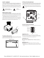
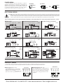
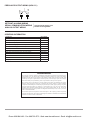
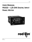
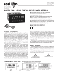
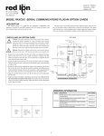
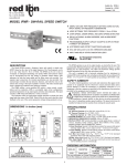
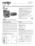
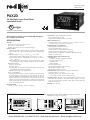
Drawing No. LP0901A Effective 04/13 PAX2D 1/8 DIN Digital Input Panel Meter Installation Guide C UL R US LISTED 3RSD PROCESS CONTROL EQUIPMENT See the Red Lion website or the enclosed USB thumbdrive for a complete user manual SPECIFICATIONS POWER: AC Power: 40 to 250 VAC, 50/60 Hz, 20 VA DC Power: 21.6 to 250 VDC, 8 W Isolation: 2300 Vrms for 1 min. to all inputs and outputs. INPUTS A and B: DIP switch selectable to accept pulses from a variety of sources including switch contacts, TTL outputs, magnetic pickups and all standard RLC sensors. LOGIC: Input trigger levels VIL = 1.5 V max.; VIH = 3.75 V min. Current sinking: Internal 7.8 KΩ pull-up to +5 VDC, IMAX = 0.7 mA. Current sourcing: Internal 3.9 KΩ pull-down, 7.3 mA max. @ 28 VDC, VMAX = 30 VDC. Filter: Damping capacitor provided for switch contact bounce. Limits input frequency to 50 Hz and input pulse widths to 10 msec. minimum. MAGNETIC PICKUP: Sensitivity: 200 mV peak Hysteresis: 100 mV Input impedance: 3.9 KΩ @ 60 Hz; Must also have SRC switch ON. (Not recommended with counting applications.) Maximum input voltage: ±40 V peak, 28 Vrms DUAL COUNT MODES: When any dual count mode is used, then User Inputs 1 and/or 2 will accept the second signal of each signal pair. The user inputs do not have the Logic/Mag, HI/LO Freq, and Sink/Source input setup switches. The user inputs are inherently a logic input with no low frequency filtering. Any mechanical contacts used for these inputs in a dual count mode must be debounced externally. The user input may only be selected for sink/source by the User Jumper placement. SENSOR POWER: +18 VDC, ± 5% @ 60 mA max.; short circuit protected PRESCALER OUTPUT: NPN Open Collector: ISNK = 100 mA max. @ VOL = 1 VDC max. VOH = 30 VDC max. Duty cycle 25% min. and 50 % max. ENVIRONMENTAL CONDITIONS: Operating Temperature Range: 0 to 50 °C Storage Temperature Range: -40 to 60 °C Vibration to IEC 68-2-6: Operational 5-150 Hz, 2 g Shock to IEC 68-2-27: Operational 25 g (10 g relay) Operating and Storage Humidity: 0 to 85% max. RH non-condensing Altitude: Up to 2000 meters CERTIFICATIONS AND COMPLIANCES: CE Approved EN 61326-1 Immunity to Industrial Locations Emission CISPR 11 Class A IEC/EN 61010-1 RoHS Compliant UL Listed: File #E179259 Type 4X Indoor Enclosure rating (Face only) IP65 Enclosure rating (Face only) IP20 Enclosure rating (Rear of unit) CONNECTIONS: High compression cage-clamp terminal block Wire Strip Length: 0.3" (7.5 mm) Wire Gauge Capacity: One 14 AWG (2.55 mm) solid, two 18 AWG (1.02 mm) or four 20 AWG (0.61 mm) CONSTRUCTION: This unit is rated NEMA 4X/IP65 for indoor use only. IP20 Touch safe. Installation Category II, Pollution Degree 2. One piece bezel/ case. Flame resistant. Synthetic rubber keypad. Panel gasket and mounting clip included. WEIGHT: 8 oz. (226.8 g) Note: Recommended minimum clearance (behind the panel) for mounting clip installation is 2.1" (53.4) H x 5.5" (140) W. DIMENSIONS In inches (mm) 1.95 (49.53) USER INPUTS: Three programmable user inputs Max. Continuous Input: 30 VDC Isolation To Sensor Input Common: Not isolated. 1.75 (44.45) 12 34 3.80 (96.52) 0.10 (2.54) 4.14 (105) 3.60 (91.44) Phone: 800.894.0412 - Fax: 888.723.4773 - Web: www.the-red-lion.net - Email: [email protected] All safety related regulations, local codes and instructions that appear in this literature or on equipment must be observed to ensure personal safety and to prevent damage to either the instrument or equipment connected to it. If equipment is used in a manner not specified by the manufacturer, the protection provided by the equipment may be impaired. Do not use this unit to directly command motors, valves, or other actuators not equipped with safeguards. To do so can be potentially harmful to persons or equipment in the event of a fault to the unit. CAUTION: Risk of Danger. Read complete instructions prior to installation and operation of the unit. SETTING THE DIP SWITCHES To access the switches, remove the meter base from the case by firmly squeezing and pulling back on the side rear finger tabs. This should lower the latch below the case slot (which is located just in front of the finger tabs). It is recommended to release the latch on one side, then start the other side latch. Warning: Exposed line voltage exists on the circuit boards. Remove all power to the meter and load circuits before accessing inside of the meter. CAUTION: Risk of electric shock. FRONT DISPLAY Main Circuit Board METER INSTALLATION The PAX2D meets NEMA 4X/IP65 requirements when properly installed. The unit is intended to be mounted into an enclosed panel. Prepare the panel cutout to the dimensions shown. Remove the panel latch from the unit. Slide the panel gasket over the rear of the unit to the back of the bezel. The unit should be installed fully assembled. Insert the unit into the panel cutout. While holding the unit in place, push the panel latch over the rear of the unit so that the tabs of the panel latch engage in the slots on the case. The panel latch should be engaged in the farthest forward slot possible. To achieve a proper seal, tighten the latch screws evenly until the unit is snug in the panel (Torque to approximately 7 in-lbs [79N-cm]). Do not over-tighten the screws. USB Connector Finger Tab INPUT SET-UP DIP SWITCHES 1 2 3 4 5 6 SAFETY SUMMARY USER INPUT JUMPER SRC Finger Tab SNK REAR TERMINALS PANEL SETTING THE INPUT DIP SWITCHES BEZEL LATCHING SLOTS PANEL LATCH LATCHING TABS The meter has six DIP switches for Input A and Input B terminal set-up that must be set before applying power. Input B LO Freq. Input B SRC. Input B MAG. Input A LO Freq. PANEL GASKET Input A SRC. Input A MAG. PANEL MOUNTING SCREWS ON 6 5 4 3 2 1 HI Freq. SNK. Logic HI Freq. SNK. Logic Factory Setting SWITCHES 1 and 4 Installation Environment The unit should be installed in a location that does not exceed the operating temperature and provides good air circulation. Placing the unit near devices that generate excessive heat should be avoided. SWITCHES 2 and 5 SNK.: Adds internal 7.8 KΩ pull-up resistor to +5 VDC, IMAX = 0.7 mA. SRC.: Adds internal 3.9 KΩ pull-down resistor, 7.3 mA max. @ 28 VDC, VMAX = 30 VDC. PANEL CUT-OUT 3.62 +.03 -.00 (92 +.8 -.0 ) LOGIC: Input trigger levels VIL = 1.5 V max.; VIH = 3.75 V min. MAG: 200 mV peak input sensitivity; 100 mV hysteresis; maximum voltage: ± 40 V peak (28 Vrms); Input impedance: 3.9 KΩ @ 60 Hz; Must also have SRC switch ON. (Not recommended with counting applications.) 1.77+.02 -.00 (45 +.5 -.0 ) SWITCHES 3 and 6 HI Frequency: Removes damping capacitor and allows max. frequency. LO Frequency: Adds a damping capacitor for switch contact bounce. Also limits input frequency to maximum 50 Hz and input pulse widths to minimum 10 msec. Phone: 800.894.0412 - Fax: 888.723.4773 - Web: www.the-red-lion.net - Email: [email protected] POWER WIRING The power supplied to the meter shall employ a 15 Amp UL approved circuit breaker for AC input and a 1 Amp, 250 V UL approved fuse for DC input. It shall be easily accessible and marked as a disconnecting device to the installed unit. This device is not directly intended for connection to the mains without a reliable means to reduce transient over-voltages to 1500 V. AC Power DC Power 1 AC/DC 2 AC/DC + 1 AC/DC - 2 AC/DC OR - 1 AC/DC + 2 AC/DC INPUT SIGNAL WIRING CAUTION: Sensor input common is NOT isolated from user input common. In order to preserve the safety of the meter application, the sensor input common must be suitably isolated from hazardous live earth referenced voltage; or input common must be at protective earth ground potential. If not, hazardous voltage may be present at the User Inputs and User Input Common terminals. Appropriate considerations must then be given to the potential of the user input common with respect to earth ground; and the common of the isolated plug-in cards with respect to input common. If you are wiring Input B, connect signal to Terminal 6 instead of 5, and set DIP switches 4, 5, and 6 to the positions shown for 1, 2, and 3. ON 6 5 4 3 2 1 ON COMM INPUT A INPUT B INPUT B INPUT A INPUT B +18VOUT COMM INPUT A INPUT B +18VOUT COMM INPUT A 6 +5V DIODE COMM 6 4 5 6 8 6 5 4 3 2 1 Count ON Rate If using single Counter B, then wire signal to 6, and Quad/Direction to 9. Set switches as shown. 4 5 6 Dual Quad/Quad; Current Sink Output Counter A & Rate B NPN O.C. 3 Input A 3 2 1 ON 3 INPUT B 5 INPUT A 4 COMM 3 Emitter Follower; Current Source Input A Dual Quad/Count; Current Sink Output NPN O.C. 5 USER 2 INPUT B 6 4 USER 1 INPUT A 5 3 Input A INPUT B COMM 4 2.2KΩ INPUT A INPUT B +18VOUT 3 6 3 2 1 ON 3 2 1 Single Counter A 5 Input A Interfacing With TTL Switch or Isolated Transistor; Current Source ON Quad; Current Sink Output ON PNP O.C. Input A 3 2 1 4 +18VOUT INPUT A 6 6 3 3 2 1 COMM COMM 5 5 INPUT B +18VOUT 4 4 3 2 1 ON 3 3 AC Input A USER 1 ON Current Sourcing Output NPN O.C. Switch or Isolated Transistor; Current Sink Resistor to limit current to 2.5 mA MAX. INPUT A 6 ON INPUT B INPUT B 5 6 COMM INPUT A 4 5 COMM COMM 3 3 2 1 Input A 4 INPUT A ON +18VOUT Current Sinking Output 3 3 2 1 +18VOUT MAGNETIC PICKUP +18VOUT 6 +18VOUT INPUT B 5 +18VOUT INPUT A 4 Two Wire Proximity, Current Source Input A COMM COMM 3 3 2 1 Input A +18VOUT ON AC Inputs From Tach Generators, Etc. +18VOUT Magnetic Pickup 3 4 5 6 8 9 6 5 4 3 2 1 Counter A & Counter B Count A NPN O.C. Count B NPN O.C. NPN O.C. Shaded areas not recommended for counting applications. USER INPUT WIRING If User Input 1 and/or 2 are wired for quadrature or directional counting, an additional switching device should not be connected to that User Input terminal. User Input terminal does not need to be wired in order to remain in inactive state. USER 3 9 10 - USER 3 USER 2 8 When the USrACt parameter is programmed to HI, the user inputs of the meter are internally pulled down to 0 V with 20 KΩ resistance. The input is active when a voltage greater than 2.2 VDC is applied. USER 2 USER 1 7 USER INPUTS USER 1 COMM. When the USrACt parameter is programmed to LO, the user inputs of the meter are internally pulled up to +3.3 V with 20 KΩ resistance. The input is active when it is pulled low (<1.1 V). Sourcing Logic (USrACt HI) USER INPUTS COMM. Sinking Logic (USrACt LO) 7 8 9 10 + V SUPPLY (30V max.) Phone: 800.894.0412 - Fax: 888.723.4773 - Web: www.the-red-lion.net - Email: [email protected] COMM PS OUT PRESCALER OUTPUT WIRING (NPN O.C.) 7 11 - + SETPOINT (ALARMS) WIRING SERIAL COMMUNICATION WIRING See appropriate plug-in card bulletin for wiring details. ANALOG OUTPUT WIRING ORDERING INFORMATION DESCRIPTION PART NUMBER Digital Input Panel Meter PAX2D000 Dual Setpoint Relay Output Card PAXCDS10 Quad Setpoint Relay Output Card PAXCDS20 Quad Setpoint Sinking Open Collector Output Card PAXCDS30 Quad Setpoint Sourcing Open Collector Output Card PAXCDS40 RS485 Serial Communications Card with Terminal Block PAXCDC10 Extended RS485 Serial Communications Card with Dual RJ11 Connector PAXCDC1C RS232 Serial Communications Card with Terminal Block PAXCDC20 Extended RS232 Serial Communications Card with 9 Pin D Connector PAXCDC2C DeviceNet Communications Card PAXCDC30 Profibus-DP Communications Card PAXCDC50 Analog Output Card PAXCDL10 LIMITED WARRANTY The Company warrants the products it manufactures against defects in materials and workmanship for a period limited to two years from the date of shipment, provided the products have been stored, handled, installed, and used under proper conditions. The Company’s liability under this limited warranty shall extend only to the repair or replacement of a defective product, at The Company’s option. The Company disclaims all liability for any affirmation, promise or representation with respect to the products. The customer agrees to hold Red Lion Controls harmless from, defend, and indemnify RLC against damages, claims, and expenses arising out of subsequent sales of RLC products or products containing components manufactured by RLC and based upon personal injuries, deaths, property damage, lost profits, and other matters which Buyer, its employees, or sub-contractors are or may be to any extent liable, including without limitation penalties imposed by the Consumer Product Safety Act (P.L. 92-573) and liability imposed upon any person pursuant to the Magnuson-Moss Warranty Act (P.L. 93-637), as now in effect or as amended hereafter. No warranties expressed or implied are created with respect to The Company’s products except those expressly contained herein. The Customer acknowledges the disclaimers and limitations contained herein and relies on no other warranties or affirmations. Phone: 800.894.0412 - Fax: 888.723.4773 - Web: www.the-red-lion.net - Email: [email protected]