1
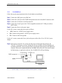
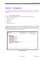
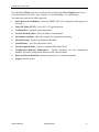
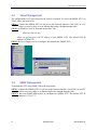
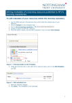
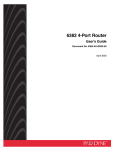
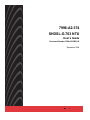
7996-A2-374
SHDSL-G.703 NTU
User’s Guide
Document Number 7996-A2-GB21-00
September 2004
7996 SHDSL NTU User’s Guide
Copyright © 2004 Paradyne Corporation.
All rights reserved.
Printed in U.S.A.
Notice
This publication is protected by federal copyright law. No part of this publication may be copied or distributed,
transmitted, transcribed, stored in a retrieval system, or translated into any human or computer language in any form
or by any means, electronic, mechanical, magnetic, manual or otherwise, or disclosed to third parties without the
express written permission of Paradyne Corporation, 8545 126th Ave. N., Largo, FL 33773.
Paradyne Corporation makes no representation or warranties with respect to the contents hereof and specifically
disclaims any implied warranties of merchantability or fitness for a particular purpose. Further, Paradyne Corporation
reserves the right to revise this publication and to make changes from time to time in the contents hereof without
obligation of Paradyne Corporation to notify any person of such revision or changes.
Changes and enhancements to the product and to the information herein will be documented and issued as a new
release to this manual.
Warranty, Sales, Service, and Training Information
Contact your local sales representative, service representative, or distributor directly for any help needed. For
additional information concerning warranty, sales, service, repair, installation, documentation, training, distributor
locations, or Paradyne worldwide office locations, use one of the following methods:
Internet: Visit the Paradyne World Wide Web site at www.paradyne.com. (Be sure to register your warranty at
www.paradyne.com/warranty.)
Telephone: Call our automated system to receive current information by fax or to speak with a company
representative.
Within the U.S.A., call 1-800-870-2221
Outside the U.S.A., call 1-727-530-2340
Document Feedback
We welcome your comments and suggestions about this document. Please mail them to Technical Publications,
Paradyne Corporation, 8545 126th Ave. N., Largo, FL 33773, or send e-mail to [email protected]. Include
the number and title of this document in your correspondence. Please include your name and phone number if you
are willing to provide additional clarification.
Trademarks
Acculink, Bitstorm, Comsphere, DSL the Easy Way, ETC, Etherloop, FrameSaver, GranDSLAM, GrandVIEW,
Hotwire, the Hotwire logo, Jetstream, MVL, NextEDGE, Net to Net Technologies, OpenLane, Paradyne, the
Paradyne logo, Paradyne Credit Corp., the Paradyne Credit Corp. logo, Performance Wizard, StormPort, TruePut are
registered trademarks of Paradyne Corporation. ADSL/R, Connect to Success, Hotwire Connected, iMarc, JetFusion,
JetVision, MicroBurst, PacketSurfer, Quick Channel, ReachDSL, Reverse Gateway, Spectrum Manager, and
StormTracker are trademarks of Paradyne Corporation. All other products and services mentioned herein are the
trademarks, service marks, registered trademarks, or registered service marks of their respective owners.
CE Marking
When the product is marked with the CE mark on the equipment label, a supporting Declaration of Conformity may be
downloaded from the Paradyne World Wide Web site at www.paradyne.com. Select Library → Technical Manuals
→ CE Declarations of Conformity.
2
September 2004
7996-A2-GB21-00
7996 SHDSL NTU User’s Guide
Table of Contents
CHAPTER 1
INTRODUCTION...........................................................................................................................5
1.1 OVERVIEW .......................................................................................................................................................5
1.2
FEATURES.........................................................................................................................................................5
1.3
APPLICATIONS ..................................................................................................................................................6
1.4
FRONT PANEL LED INDICATORS ......................................................................................................................7
CHAPTER 2
HARDWARE INSTALLATION ....................................................................................................8
2.1 REAR PANEL CONNECTORS ..............................................................................................................................8
2.2
INSTALLATION ..................................................................................................................................................9
CHAPTER 3
MANAGEMENT ..........................................................................................................................10
3.1 CONSOLE MANAGEMENT ...............................................................................................................................10
3.2
TELNET MANAGEMENT ..................................................................................................................................12
3.3
SNMP MANAGEMENT ...................................................................................................................................12
CHAPTER 4
SYSTEM SETUP ..........................................................................................................................13
4.1 LOGIN ............................................................................................................................................................13
4.2
MAIN MENU ...................................................................................................................................................14
4.3
CONFIGURATION ............................................................................................................................................15
4.4
LOGOUT .........................................................................................................................................................22
CHAPTER 5
OPERATION MODE ...................................................................................................................23
5.1 SELECTING DEVICE ........................................................................................................................................24
5.2
SELECTING MODE ..........................................................................................................................................25
CHAPTER 6
MAINTENANCE..........................................................................................................................26
6.1 PERFORMANCE ...............................................................................................................................................26
6.2
ALARM MONITORING .....................................................................................................................................33
6.3
LOOPBACK TEST ............................................................................................................................................34
6.4
SYSTEM MAINTENANCE .................................................................................................................................38
6.5
SYSTEM RESET AND SOFTWARE DOWNLOAD .................................................................................................41
CHAPTER 7
TROUBLESHOOTING ...............................................................................................................44
APPENDIX A SPECIFICATIONS.........................................................................................................................45
APPENDIX B PIN ASSIGNMENTS .....................................................................................................................46
List of Figures
Figure 1-1 Applications of 7996-A2-374 ........................................................6
Figure 1-2 7996-A2-374 Front View ..............................................................7
Figure 2-1 7996-A2-374 Rear Panel Connectors-DC power ...............................8
Figure 2-2 7996-A2-374 Rear Panel Connectors-AC power ...............................8
Figure 3-1 Main Menu ............................................................................... 10
Figure 4-1 Main Menu ............................................................................... 13
Figure 4-2 Configuration Menu ................................................................... 15
7996-A2-GB21-00
September 2004
3
7996 SHDSL NTU User’s Guide
Figure 4-3 System Configuration Screen...................................................... 16
Figure 4-4 Local Management Port Configuration Screen................................ 16
Figure 4-5 System Date and Time Setting Screen ......................................... 17
Figure 4-6 Password Configuration Screen ................................................... 18
Figure 4-7 SNMP Configuration Screen ........................................................ 19
Figure 4-8 SHDSL Interface Configuration Screen ......................................... 20
Figure 4-9 E1 Interface Configuration Screen I ............................................. 21
Figure 5-1 Operation Mode Indication ......................................................... 23
Figure 5-2 Select Device Menu ................................................................... 24
Figure 5-3 Remote Device Configuration Main Menu ...................................... 24
Figure 5-4 Select NE Mode Menu ................................................................ 25
Figure 6-1 Performance Data Menu............................................................. 26
Figure 6-2 SHDSL Performance Data Menu .................................................. 26
Figure 6-3 Current Quarter Performance Screen for SHDSL ............................ 27
Figure 6-4 Previous 96 Quarters Performance Screen for SHDSL ..................... 27
Figure 6-5 Current & Previous 7 Days Performance Screen for SHDSL.............. 28
Figure 6-6 Clear Performance Data Screen for SHDSL ................................... 28
Figure 6-7 Current Quarter Performance Screen for E1 .................................. 29
Figure 6-8 Previous 96 Quarters Performance Screen for E1 ........................... 30
Figure 6-9 Current & Previous 7 Days Performance Screen for E1.................... 30
Figure 6-10 Clear Performance Data Screen for E1........................................ 31
Figure 6-11 Threshold Set Menu................................................................. 31
Figure 6-12 SHDSL Threshold Setup Screen................................................. 31
Figure 6-13 E1 Threshold Setup Screen....................................................... 32
Figure 6-14 Current Alarm Status Screen .................................................... 33
Figure 6-15 Alarm History Screen............................................................... 33
Figure 6-16 Test and Loopback Menu .......................................................... 34
Figure 6-17 SHDSL Loopback Screen .......................................................... 34
Figure 6-18 SHDSL BER Test Screen ........................................................... 35
Figure 6-19 E1 Loopback Screen ................................................................ 36
Figure 6-20 E1 BER Test Screen ................................................................. 37
Figure 6-21 Configuration Database Maintenance Menu ................................. 38
Figure 6-22 Reset & Software Download Menu ............................................. 41
4
September 2004
7996-A2-GB21-00
7996 SHDSL NTU User’s Guide
Chapter 1
1.1
Introduction
Overview
This user’s manual provides general information about the features, functions and operation of
the 7996-A2-374 SHDSL NTU.
The 7996-A2-374 is a Network Termination Unit (NTU) that utilizes SHDSL technology,
combining the best of 2B1Q SDSL and HDSL2 to achieve fast and efficient data transmission in
both directions, over a single copper telephone line.
The 7996-A2-374 has an industry standard E1 interface. Based on TC-PAM coding, the
7996-A2-374 supports data rates of up to 2,048 kbps. It is suitable for leased line applications
such as video conferencing, Internet access, and Digital Data Network (DDN) access.
Featuring remote control capability, the local 7996-A2-374 is able to perform configuration,
performance monitoring, querying, diagnostics, and all maintenance functions over the remote
NTU via the DSL line.
1.2
Features
TDM-based SHDSL NTUs guarantee real bandwidth without the large overhead required
by ATM-based NTUs
Full remote control capability via SHDSL Embedded Operation Channel
Complies with ITU-T G.991.2 (G.shdsl)
E1 DTE interface
Versatile loopbacks for diagnostics
Built-in test pattern generator and detector
SHDSL and E1 line performance monitoring (PM)
96-quarter-hour / 7-day PM storage
Local control via RS-232 management port (VT100) and LAN port (Telnet access)
SNMP management through Ethernet LAN port
Software download capability
7996-A2-GB21-00
September 2004
5
7996 SHDSL NTU User’s Guide
1.3
Applications
Figure 1-1 shows the applications of the 7996-A2-374 SHDSL NTU.
Figure 1-1 Applications of 7996-A2-374
6
September 2004
7996-A2-GB21-00
7996 SHDSL NTU User’s Guide
1.4
Front Panel LED Indicators
The 7996-A2-374 has eight LED indicators. These LEDs indicate power status, diagnostics,
machine status, data activity, and alarm conditions.
Figure 1-2 7996-A2-374 Front View
LED
Color
Indicator
Mode Function
Power is supplied
No power is connected
Bit Error testing
TEST
Self testing
Normal operation
NT mode enabled
NT
LT mode enabled
Major alarm detected
ALARM
No major alarm detected
Loopback testing
LB
Normal operation
E1 connection is working
E1
E1 connection is not working
Loss of signal (DSL link is out of service or not
On
connected)
DSL LOS Red
Blink DSL link is training
Off
DSL link is connected
On
Self-test error
ERR
Yellow Blink Bit error test error
Off
Normal operation
POWER
On
Off
On
Green Blink
Off
On
Green
Off
On
Red
Off
On
Yellow
Off
On
Green
Off
Green
Table 1-1 7996-A2-374 LEDs
Note: The average training period for the SHDSL line is one minute and forty seconds. If the training
period exceeds three minutes, or it fails (the DSL LOS LED keeps blinking), it means the line
quality is poor or the link distance is too long for the SHDSL NTU to train. Contact your service
provider.
7996-A2-GB21-00
September 2004
7
7996 SHDSL NTU User’s Guide
Chapter 2
2.1
Hardware Installation
Rear Panel Connectors
There are two types of rear panels for the 7996-A2-374. Their only difference is the power
supply: –48 VDC or 110/220 VAC.
Figure 2-1 7996-A2-374 Rear Panel Connectors – DC power
Figure 2-2 7996-A2-374 Rear Panel Connectors – AC power
Interface
Description
–48V FG PG
The –48 VDC version has three pins: –48V, FG, PG (Fig.2-1).
Power
The AC version has a power jack and a power switch (Fig.2-2).
Console
DB9 female connector for connection to a PC COM port
LAN
RJ45 connector for SNMP network management
E1
RJ45 connector for a 120 ohm, balanced E1 interface
TX and RX
BNC connector for a 75 ohm, unbalanced E1 interface
LINE
RJ45 connector for the SHDSL connection
Table 2-1 7996-A2-374 Rear Connectors
8
September 2004
7996-A2-GB21-00
7996 SHDSL NTU User’s Guide
2.2
Installation
Follow the step-by-step instructions below for the hardware installation:
Step 1 Connect the LINE port to your DSL line.
Step 2 Connect the LAN port to the SNMP management network with an RJ45 connector cable.
Step 3 Connect the E1 interface to the Data network.
Step 4 Connect the Console port to the VT100 compatible terminal or PC COM port with an
RS232 cable.
Step 5 Connect the Power to the power input.
For the DC version, connect the power pins as follows:
–48V: Connect to –48VDC power supply source.
PG: Connect to the ground of –48VDC power supply source.
FG : Connect to the frame ground.
For the AC version, connect the Power jack to the power cable of the 110 or 220 VAC power
adapter.
Step 6 After power on (for the AC version, turn the power switch to the ON position), the
7996-A2-374 performs a self-test. During the self-test, all LEDs will keep flashing back
and forth sequentially. The test items include system RAM, flash memory and application
software. If an error is found in RAM, the ALARM LED will be ON. If an error is found
in flash memory or application software, the ALARM LED will keep flashing.
Caution: If the SHDSL NTU fails to power on, or it malfunctions, first verify that the
power supply is correctly connected, and then power it on again.
7996-A2-GB21-00
September 2004
9
7996 SHDSL NTU User’s Guide
Chapter 3
Management
This chapter describes the three ways to manage the SHDSL NTU: Console, Telnet and SNMP.
Chapters 4 to 6 cover the configuration and maintenance of the SHDSL NTU in a console or
Telnet session.
3.1
Console Management
Configure the following parameters for your VT100 terminal emulation program:
Baud rate: 38,400 bps
Parity: None
Data bits: 8
Stop bit: 1
Flow control: None
After the session parameters are set up, start the VT100 emulator program on the PC. The Press
Any Key to Login… message will be shown in the middle of the screen. Press any key. When
the login prompt appears, type the password and press the Enter key to display the main menu as
shown below. For initial login, no password is required.
Figure 3-1 Main Menu
10
September 2004
7996-A2-GB21-00
7996 SHDSL NTU User’s Guide
Press the Up and Down arrow keys to select fields, and press the Left and Right arrow keys to
select the parameters of fields. Type <Ctrl-X > to exit and <Enter > for confirmation.
The main menu includes the following fields:
Select Device (Local/Remote): Select the SHDSL NTU to be configured. (Only appears in
LT mode.)
Select NE Mode (LT/NT): Select NT or LT operation mode.
Configuration: Configure system parameters.
Current Alarm & Status: Show the status of current alarms.
Performance Statistics: Show the statistics of performance monitoring.
Threshold Setup: Set the day and quarter threshold.
Alarm History: View all of the alarm records.
Test & Loopback Status: Perform a loopback, BER and self-test.
Configuration Database Maintenance: Upload, download, save the configuration
database, and set the configuration database to the factory defaults.
Reset & Software Download: Perform a system reset or software download.
Logout: Exit the system.
7996-A2-GB21-00
September 2004
11
7996 SHDSL NTU User’s Guide
3.2
Telnet Management
The configurations in a Telnet session are the same as in console. To access the SHDSL NTU via
Telnet, follow the steps below:
STEP 1: Connect the SHDSL NTU’s LAN port to the Network Interface Card (NIC) in a PC
using a crossover cable, or to an Ethernet hub using a straight-through cable.
STEP 2: In Windows, click on Start and choose Run. Type:
telnet xxx.xxx.xxx.xxx.
where xxx.xxx.xxx.xxx is the IP address of your SHDSL NTU. The default NTU IP
address is 172.16.7.37.
STEP 3: Refer to Chapters 4 to 6 to configure and maintain the SHDSL NTU.
3.3
SNMP Management
To manage the NTU using SNMP, follow the steps below:
STEP 1: Connect the SHDSL NTU’s LAN port to the Network Interface Card (NIC) in your PC
with a cross-over cable, or an Ethernet hub with a straight-through cable.
STEP 2: Run your SNMP MIB browser to configure the SHDSL NTU. The default NTU IP
address is 172.16.7.37.
12
September 2004
7996-A2-GB21-00
7996 SHDSL NTU User’s Guide
Chapter 4
4.1
System Setup
Login
Configure the following parameters for your VT100 terminal emulation program.
Console session parameters (factory default)
Baud rate: 38400 bps
Parity: None
Data bits: 8
Stop bit: 1
Flow control: None
Run the VT100 emulator program. In a while, the Press Any Key to Login… message appears.
Press any key. When a login prompt appears, type a password and then press the Enter key to
display the main menu as shown below. No password is required the first time you log in.
Figure 4-1 Main Menu
7996-A2-GB21-00
September 2004
13
7996 SHDSL NTU User’s Guide
4.2
Main Menu
Press the Up and Down arrow keys to select fields, and press the Left and Right arrow keys to
select the parameters of fields. Type <Ctrl-X > to exit and <Enter > for confirmation.
The main menu includes the following fields:
Select Device: Select the device to be configured. This field is only available in LT
mode.
Select NE Mode (LT/NT): Select NT or LT operation mode. The factory default is LT
mode.
Configuration: Configure system parameters.
Current Alarm & Status: Show the status of current alarms.
Performance Statistics: Show the statistics of performance monitoring.
Threshold Setup: Set the thresholds for system performance monitoring.
Alarm History: View and clear alarm records.
Test & Loopback Status: Perform a loopback, BER and self-test
Configuration Database Maintenance: Upload; download; save the configuration
database; and set the configuration database to factory default.
Reset & Software Download: Perform a system reset or software download
Logout: Exit the system
14
September 2004
7996-A2-GB21-00
7996 SHDSL NTU User’s Guide
4.3
Configuration
After you log in to the device, press the Up or Down arrow key to select the Configuration field
from the main menu and then press the Enter key to go to the Configuration Menu.
Seven fields can be selected from the Configuration Menu. The detail of each field is explained
in the following sections. Figure 4-2 shows the content of the configuration menu.
Figure 4-2 Configuration Menu
4.3.1
System configuration
Select Main Menu>Configuration>System Configuration to go to the System Configuration
screen shown in Figure 4-3. The following parameters can be configured there.
Device Name: Enter proper characters for system identification. The maximum length of
the device name is eight characters. Only alphabetic and numeric characters are valid.
Timing Source: In LT Mode, the user can choose a timing source (Internal, E1-LOOP,
SHDSL-LOOP, or Independent) by using the Left and Right arrow keys. In NT Mode, the
timing source is not configurable.
Note: To receive the clock from the E1 interface at both sides, both of the 7996-A2-374
devices should be set to Independent.
Use the Up/Down arrow key to exit or confirm the setting.
7996-A2-GB21-00
September 2004
15
7996 SHDSL NTU User’s Guide
Figure 4-3 System Configuration Screen
4.3.2
Local Management Port Configuration
Select Main Menu>Configuration>Management Port Configuration to go to the Local
Management Port Configuration screen shown in Figure 4-4. The factory-default setting for
Baud Rate is 38400 bps. Press the Left or Right arrow key to select Baud Rate and use the Up or
Down arrow key to exit or confirm the setting.
Figure 4-4 Local Management Port Configuration Screen
16
September 2004
7996-A2-GB21-00
7996 SHDSL NTU User’s Guide
4.3.3
System Date and Time Setting
Select Main Menu>Configuration>System Date and Time Setting to go to the System Date
and Time Setting screen shown in Figure 4-5.
Figure 4-5 System Date and Time Setting Screen
Select Synchronize Remote Date & Time to synchronize the system date and time of the
remote device with the local machine.
7996-A2-GB21-00
September 2004
17
7996 SHDSL NTU User’s Guide
4.3.4
Password Change
For security purposes, set up the password after initial login.
Select Main Menu>Configuration>Change Password to enter the System Change Password
screen, which is shown in Figure 4-6.
Figure 4-6 Password Configuration Screen
Note 1: The maximum length of the password is eight characters.
Note 2: Only alphabetic and numeric characters may be used for the password.
Note 3: Every time you change the password, remember to save the configuration
database.
4.3.5
SNMP & TFTP Configuration
Before connecting to the SNMP management system, configure the following parameters. The
parameters for SNMP configuration are explained as the following:
Node IP Address: Specify the IP address for the device. The default address is 172.16.7.37.
Node IP Subnet Mask: Specify a subnet mask for the IP address. The default mask is
255.255.0.0.
Gateway IP: Set a gateway IP address. The default address is 172.16.7.40.
Trap IP Address 1: Set the host IP address for traps.
Trap Port 1: 162 (default), 62000, 62001, 62002 (three optional ports).
Trap IP Address 2: Set the second host IP address for traps.
Trap Port 2: 162 (default), 62000, 62001, 62002 (three optional ports).
Read Community String: Enter a string for reading identification.
Write Community String: Enter a string for writing identification.
Trap Community String: Enter a string for device identification.
18
September 2004
7996-A2-GB21-00
7996 SHDSL NTU User’s Guide
The user can define up to two trap hosts using the Trap IP address 1 and Trap IP address 2. Each
trap port is also changeable. The default trap port is 162. The device sends traps to these hosts
when the traps are generated. If a trap host is on the same IP subnet as the device, the trap can be
sent to the host directly; otherwise, a gateway must be used. Figure 4-7 shows all of the
parameters for SNMP configuration.
The parameters for TFTP configuration are:
File Server IP Address: Enter the IP address of the TFTP server.
Software Download Filename: Enter the file name for software upgrade.
Configuration Database Up/Download Filename: Enter the file name for the configuration
database uploading or downloading.
Figure 4-7 SNMP Configuration Screen
7996-A2-GB21-00
September 2004
19
7996 SHDSL NTU User’s Guide
4.3.6
SHDSL Interface Configuration
The parameters in the SHDSL Interface Configuration menu are shown in Figure 4-8. The
7996-A2-374 can support two modes: transparency and non-transparency for E1. The Data Rate
is fixed at the speed of 1544 kbps (N=24) for both modes.
Power backoff: In access networks, loop lengths and noise conditions differ significantly from
pair to pair. While 13.5 dBm transmit power is required for worst-case noise conditions, many
lines will not require such power levels. G.SHDSL includes a power back-off algorithm that
enables modems to adjust their transmitting power according to conditions on the line. Operators
can use this feature to manage and reduce crosstalk noise on the network.
GTI Standard: There are three options:
•
Annex A (G.922.1 G.SHDSL Annex A compliant)
•
Annex B (G.992.1 G.SHDSL Annex B compliant)
•
Annex AB.
The LT mode supports Annex A and Annex B. The NT mode supports Annex A, Annex B and
Annex AB. The default setting for LT is Annex A, and for NT is Annex AB. If the devices train
with their default modes, Annex A will be used.
Figure 4-8 SHDSL Interface Configuration Screen
20
September 2004
7996-A2-GB21-00
7996 SHDSL NTU User’s Guide
4.3.7
E1 Interface Configuration
When you select Main Menu>Configuration>E1 Interface Configuration, one of the two
different E1 Interface Configuration screens is displayed. In the SHDSL Interface Configuration,
if the field E1 Transparency is enabled, then the time slots of the E1 interface will be
unconfigurable. The screen is shown in Figure 4-9. It allows the user to set the field Line Drive
to 75 ohm or 120 ohm, and to enable the field Local Loopback Send All 1, but the field Line
Code is not selectable. (It is fixed as HDB3.) A practical SHDSL line rate is shown at the bottom
of the screen.
Figure 4-9 E1 Interface Configuration Screen I
Figure 4-10 shows another E1 interface configuration screen, when E1 Transparency is
disabled from the SHDSL interface menu. The time slot becomes configurable. The Line Drive
and Local Loopback Send All 1 settings are explained in the previous section. The user can also
select Line Type: E1 / E1-CRC and configure the Time Slot Map.
In the E1 time slot map, there are 31 user-selectable time slots. The user can enter 1 to enable, or
0 to disable the time slot. After completing the configuration, use the Up/Down arrow keys to
highlight the Confirm field, and press Enter to confirm the settings.
Figure 4-10 E1 Interface Configuration Screen II
7996-A2-GB21-00
September 2004
21
7996 SHDSL NTU User’s Guide
4.4
Logout
To log out of the system, move the cursor to the Logout field from the main menu by using the
Up or Down arrow key.
Figure 4-11 System Logout
After pressing the Enter key, a prompt as shown below will ask you to Press any key to login.
Then you are prompted to log in once again.
22
September 2004
7996-A2-GB21-00
7996 SHDSL NTU User’s Guide
Chapter 5
Operation Mode
There are two access privileges for system operation: Read mode and Write mode. In Read
mode, the user can only view information from the terminal except changing the password. In
Write mode, the user can view system information and change system parameters from the
terminal. Figure 5-1 shows how this is indicated: <WRITE> is displayed in the lower right
corner of the screen, showing the system is managed in Write mode.
Figure 5-1 Operation Mode Indication
Upon first login, you will enter the Write mode. A password is not required upon initial login.
Note: When the same password is used for both modes, Write mode always gets a higher
priority. You can change the password for both modes by selecting Main
Menu>Configuration> Change Password.
7996-A2-GB21-00
September 2004
23
7996 SHDSL NTU User’s Guide
5.1
Selecting Device
Select Main Menu>Select Device to configure the local or remote device. This field is only
available in LT mode. The default setting of the Select Device is local. If you change Select
Device to Remote shown in Figure 5-2, you can configure the remote device via the DSL line.
Figure 5-2 Select Device Menu
The main menu of the remote configuration is a little different from that of the local
configuration. Figure 5-3 shows the fields included in the remote Main Menu: Select NE Node,
Configuration, Current Alarm Status, Performance Statistics, Threshold Setup, DTE Status,
Loopback Status, Configuration Database Maintenance, Reset and Return to Local. The details
of these fields are the same as those of the local main menu and have been explained in other
sections. Select the Return to Local field to go back to the local device configuration.
Figure 5-3 Remote Device Configuration Main Menu
24
September 2004
7996-A2-GB21-00
7996 SHDSL NTU User’s Guide
5.2
Selecting Mode
Select Main Menu>Select NE Mode (LT/NT) to configure device mode: LT (Line Termination
or NT (Network Termination). The Select NE Mode Menu is shown in Figure 5-4. The factory
default is LT mode.
Figure 5-4 Select NE Mode Menu
The NT LED on front panel will light when NT is selected.
NT Mode: System timing is not configurable in this mode. The default first priority is from
SHDSL-LOOP, the second is from Internal.
LT Mode: You can set the timing to Internal, SHDSL-LOOP, E1-LOOP and
Independent.
7996-A2-GB21-00
September 2004
25
7996 SHDSL NTU User’s Guide
Chapter 6
Maintenance
The chapter describes performance monitoring, alarm monitoring, and loopback test.
6.1
Performance
The SHDSL NTU allows you to perform SHDSL Performance Monitoring and E1 Performance
Monitoring, set up thresholds for the SHDSL Interface, and set up thresholds for the E1
Interface.
6.1.1
SHDSL Performance Monitoring
Select Main Menu>Performance Statistics to enter the Performance Data Menu shown in
Figure 6-1. You can select either the SHDSL Performance or E1 Performance field on the
menu. To configure SHDSL performance monitoring, choose SHDSL Performance.
Figure 6-1 Performance Data Menu
In both the SHDSL Performance and E1 Performance menus, the performance of near and far
ends can be monitored. The reporting of all performance data is per quarter hour. You can view
the data of the current quarter-hour, previous 96 quarter-hours, or current and previous 7 days, or
choose the Clear Performance Data option to clear the data from both the Near-End and FarEnd. Figures 6-3 to 6-5 show example screens for SHDSL performance monitoring.
Figure 6-2 SHDSL Performance Data Menu
26
September 2004
7996-A2-GB21-00
7996 SHDSL NTU User’s Guide
The NTU monitors four parameters: ES, SES, UAS, and LOSW.
ES (Errored Seconds): Specifies the amount of seconds with one or more CRC errors.
SES (Severely Errored Seconds): Specifies the amount of seconds with 25 or more CRC
errors.
UAS (Unavailable Seconds): Counts the cumulative number of seconds in which the
interface was unavailable during the measured period.
LOSW: Loss of Synchronization Word.
Update the monitored data immediately by selecting Refresh. The parameter Elapsed Seconds
represents the time (in seconds) passed in the current quarter hour. The maximum value of the
Elapsed Seconds is 900 seconds.
Figure 6-3 Current Quarter Performance Screen for SHDSL
In the screen containing the Previous 96 Quarters Performance, you can press the Left and Right
arrow keys on the fields of Performance Data to select the monitored parameter (ES, SES, UAS
or LOSW). Then press the Enter key to view the data for the day.
Figure 6-4 Previous 96 Quarters Performance Screen for SHDSL
7996-A2-GB21-00
September 2004
27
7996 SHDSL NTU User’s Guide
On the Current & Previous 7 Days Performance screen, data for the previous seven days and
information about valid intervals are displayed. For the statistics of a current day, the number of
valid intervals is counted per quarter hour. The accumulation of the number starts from the
beginning of a day. Select Refresh to update the monitored data.
Figure 6-5 Current & Previous 7 Days Performance Screen for SHDSL
Clear the current or history performance data by selecting the Main Menu>Performance
Statistics> SHDSL Performance> Clear Performance Data option. First, select a performance
type: Current or History. Second, select a parameter (ES, SES, UAS or ALL) for the
Performance Data field. Then select Clear to perform the clearing of the data. The screen is
shown in Figure 6-6.
Figure 6-6 Clear Performance Data Screen for SHDSL
28
September 2004
7996-A2-GB21-00
7996 SHDSL NTU User’s Guide
6.1.2
E1 Performance Monitoring
Select Main Menu> Performance Statistics> E1 Performance to go to the E1 performance
monitoring screen. Figures 6-7 to 6-9 show example screens for the E1 performance monitoring.
The E1 performance monitoring for the current quarter-hour is shown in Figure 6-7. The
parameters that are monitored are:
LCV (Line Coding Violation): The occurrence of either a Bipolar Violation (BPV) or
Excessive Zeroes (EXZ) error event.
PCV (Path Coding Violation): A frame synchronization bit error in the E1-noCRC
formats, or a CRC or frame synch. bit error in the E1-CRC formats.
ES (Errored Seconds): A second with one or more PCV events, CS events, Out of Frame
defects or a detected AIS defect.
SES (Severely Errored Seconds): A second with 832 or more PCV error events OR one or
more Out of Frame defects.
SEFS (Severely Errored Framing Seconds): A second with one or more Out of Frame
defects or a detected AIS defect.
UAS (Unavailable Seconds): Calculated by counting the number of seconds that the
interface is unavailable.
CSS (Controlled Slip Seconds): A one-second interval containing one or more controlled
slips.
DM (Degraded Minutes): The minutes in which the estimated error rate exceeds 1E-6 but
does not exceed 1E-3.
CS (Controlled Slip): The replication or deletion of the payload bits of a frame.
FE (Framing Error): The occurrence of a particular density of Framing Error events, Out
of Frame.
Select Refresh to update the monitored data immediately. The parameter Elapsed Seconds
represents the time passed (in seconds) in the current quarter-hour. The maximum value of the
Elapsed Seconds is 900 seconds.
Figure 6-7 Current Quarter Performance Screen for E1
7996-A2-GB21-00
September 2004
29
7996 SHDSL NTU User’s Guide
Figure 6-8 shows an example screen for the Previous 96 Quarters Performance reporting. Use the
Left/Right arrow keys to select the reporting criteria for the Performance Data by choosing the
applicable monitored parameter. After selecting a parameter, press the Enter key to confirm the
new value, and to view the monitored data for a particular day.
Figure 6-8 Previous 96 Quarters Performance Screen for E1
On the Current & Previous 7 Days Performance screen, shown below, the data of the previous
seven days and the information about valid intervals are displayed. For the statistics of a current
day, the number of valid intervals is counted per quarter. The accumulation of the number starts
from the beginning of a day. Use the Refresh command to update the data that is monitored.
Figure 6-9 Current & Previous 7 Days Performance Screen for E1
30
September 2004
7996-A2-GB21-00
7996 SHDSL NTU User’s Guide
Clear the current or history performance data by selecting the Main Menu>Performance
Statistics> E1 Performance> Clear Performance Data option. First, select a performance
type: Current or History. Second, select a parameter for the Performance Data field. Then
select Clear to perform the clearing of the data. The screen is shown below.
Figure 6-10 Clear Performance Data Screen for E1
6.1.3
Threshold Setting for SHDSL Interface
Select Main Menu>Threshold Setup to go to the menu of Performance Threshold Set shown
below. Two fields can be selected: SHDSL threshold and E1 threshold. Press the Up or Down
arrow key to select SHDSL Threshold.
Figure 6-11 Threshold Set Menu
The threshold is expressed in seconds. The valid range of the threshold for a quarter hour is from
0 to 900 seconds, and the valid range for a day is from 0 to 86400 seconds. The Unit for
parameter SNR and Loop Attenuation are expressed as decibels. For SNR, (signal-to-noise ratio)
the valid range of the threshold is from 1 to 15 dB. For Loop Attenuation, the valid range is from
1 to 127 dB. Once these thresholds are set, an alarm will be generated when the error detected is
greater than the thresholds within the interval.
Figure 6-12 SHDSL Threshold Setup Screen
7996-A2-GB21-00
September 2004
31
7996 SHDSL NTU User’s Guide
6.1.4
Threshold Setting for E1 Interface
Select Main Menu>Threshold Setup> E1 Threshold Setup to display the E1 THRESHOLD
SETUP screen, shown below.
Figure 6-13 E1 Threshold Setup Screen
On the screen, the threshold units for ES, SES, SEFS, UAS and CSS are counted in seconds. The
valid range for the threshold per quarter-hour is from 0 to 900 seconds, and the valid range for a
day is from 0 to 86400 seconds. The threshold of the DM parameter is counted in minutes, with
the valid quarter-hourly threshold range from 0 to 15 minutes, and daily range from 0 to 1440
minutes. The thresholds of LCV and PCV are counted by the number of times error events
occurred. After these thresholds are set, an alarm will be generated when the errors counted
exceeds the specified threshold intervals.
32
September 2004
7996-A2-GB21-00
7996 SHDSL NTU User’s Guide
6.2
Alarm Monitoring
The Alarm Monitoring menu displays current alarm status and alarm history, and allows you to
clear alarms.
6.2.1
Viewing Current Alarm Status
Select Main Menu>Current Alarm & Status to view the device’s current alarm status. The
system provides two classes of alarms: major and minor. Use the Up/Down arrow key to select
field Exit for page exit, Refresh for updating data, PgUp for page up, and PgDn for page down.
Figure 6-14 Current Alarm Status Screen
6.2.2
Viewing Alarm History
Select Main Menu>Alarm History to view the device alarm history. Use the Refresh function
to update the status and press the PgUp and PgDn keys to switch the page. To clear the device
alarm history, use the Clear function.
Figure 6-15 Alarm History Screen
7996-A2-GB21-00
September 2004
33
7996 SHDSL NTU User’s Guide
6.3
Loopback Test
Select Main Menu>Test & Loopback Status to enter the TEST AND LOOPBACK Menu
shown in Figure 6-16. From the Test and Loopback Status menu you can execute SHDSL, E1
and system tests. The system allows only one loopback at a time.
Figure 6-16 Test and Loopback Menu
6.3.1
SHDSL Loopback Test
Select Main Menu> Test & Loopback Status> SHDSL Loopback, to go to the SHDSL
loopback screen.
Figure 6-17 SHDSL Loopback Screen
There are four types of the SHDSL loopback.
•
Line loopback: To perform a loopback toward the line.
•
Local loopback: To perform a loopback toward the DTE. This loopback will terminate
the SHDSL link.
•
Remote line loopback: To perform the remote line loopback.
•
Remote payload loopback: To perform the remote payload loopback.
To release a loopback, choose Release to return to normal operation.
34
September 2004
7996-A2-GB21-00
7996 SHDSL NTU User’s Guide
6.3.2
SHDSL BER Test
Select Main Menu> Test & Loopback Status> SHDSL BER Test to enter the SHDSL BER
test screen. The screen is shown in Figure 6-18. The fields in the screen are described below:
Test Period: enter the time for testing. (00:00:00 specifies that the test will be continuous.)
Test Pattern: 2047 and 2^15-1 patterns are available for the test. Normal means there is no
pattern sent.
Test Switch: Use the Up/Down key to move the cursor to this field and select Start to
perform the test.
To perform the BER Test, you have to select a test pattern in the Test Pattern field first. Then
move the cursor to Start in the Test Switch field and press Enter to start the test.
After performing a test, the test result will appear on the screen immediately. The test results
include the statistics of Elapsed seconds, Bit Errors and Bit Error Ratio. Press the E key to stop
the test, press 1–7 to set the rate for Error Insertion (where 1 means the rate is 10E-1, 2 means
the rate is 10E-2, and so on), or press 0 to stop the error insertion.
During the test, the system will refresh the screen once per second.
Figure 6-18 SHDSL BER Test Screen
7996-A2-GB21-00
September 2004
35
7996 SHDSL NTU User’s Guide
6.3.3
E1 Loopback Test
After entering Main Menu>Test & Loopback Status>E1 Loopback, shown in Figure 6-23,
four fields can be chosen on the E1 loopback screen.
Figure 6-19 E1 Loopback Screen
On the screen, there are four fields selectable via the Left/Right arrow key and explained below:
Release: Return to normal operation.
Local: Perform an E1 local loopback test. The loopback diagram is shown below.
Line: Perform an E1 line loopback test. The loopback diagram is shown below.
36
September 2004
7996-A2-GB21-00
7996 SHDSL NTU User’s Guide
Payload: Perform an E1 payload loopback test. The loopback diagram is shown below.
6.3.4
E1 BER Test
Select Main Menu> Test & Loopback Status> E1 BER Test to enter the E1 interface BER test
screen. The screen is shown in Figure 6-24. The fields on the screen are described below:
Test Period: Enter the time for testing. (00:00:00 indicates that the test will be continuous.)
Test Pattern: 2047 and PRBS (2^15-1) patterns are available for the test. Parameter
Normal indicates that there is no pattern sent.
Test Switch: The user has to use the Up/Down key to move the cursor to this field and
select Start to perform the test
After performing a test, the test result will appear on the screen immediately. The test results
include the statistics of Elapsed seconds, Bit Errors and the Bit Error Ratio. Press the E key to
stop the test, press 1–7 to set the rate for Error Insertion (where 1 means the rate is 10E-1, 2
means the rate is 10E-2, and so on), or press 0 to stop the error insertion.
Figure 6-20 E1 BER Test Screen
7996-A2-GB21-00
September 2004
37
7996 SHDSL NTU User’s Guide
6.3.5
System Self-Test
Select Main Menu>Test & Loopback Status>Self test to perform a system self-test. The
system will perform a self-test and then show the results on the screen. During the test, the traffic
will be interrupted.
6.4
System Maintenance
You can save, upload, or download the configuration database, or restore the configuration
database to the factory default setting from the Configuration Database Maintenance screen.
Figure 6-21 Configuration Database Maintenance Menu
6.4.1
Saving Configuration Database
Select Main Menu> Configuration Database Maintenance> Save Configuration Database to
save the system configuration file. A message as shown below will appear for confirmation.
Choose Save by using the Up/Down key. After the confirmation, the file will be saved in system
flash memory.
Caution: Always perform this action after making any change from the menu.
Otherwise, the change will be lost after the system is restarted.
38
September 2004
7996-A2-GB21-00
7996 SHDSL NTU User’s Guide
6.4.2
Uploading Configuration Database via X-modem
Select Main Menu> Configuration Database Maintenance> Upload Configuration
Database (X_Modem) to upload the system configuration file via X-modem. A message as
shown below will appear for confirmation. Choose UpLoad to perform the uploading. And then
perform the following procedure.
Procedure for upload:
Step 1 Select the function for file transfer (receive/download) from the terminal emulation
program you use.
Step 2 Select X-modem protocol for file transfer.
Step 3 Enter the file name with the directory to be received.
Step 4 Execute the file transfer function.
Note: The maximum wait time for the system is 50 seconds. If a timeout message
appears, repeat the above procedure.
6.4.3
Uploading Configuration Database via TFTP
Select Main Menu> Configuration Database Maintenance> Upload Configuration
Database (TFTP) to upload the system configuration file via the TFTP server. A message as
shown below will appear for confirmation. Choose UpLoad.
Note: Go to the Main Menu>Configuration>SNMP Configuration screen to enter the
IP address of the TFTP server and the file name you would like to upload before
performing the upload.
7996-A2-GB21-00
September 2004
39
7996 SHDSL NTU User’s Guide
6.4.4
Downloading Configuration Database via X-modem
Select Main Menu> Configuration Database Maintenance> Download Configuration
Database (X_Modem) to download the system configuration file via X-modem. A message as
shown below will appear for confirmation. Choose DownLoad. Then perform the following
procedure. The configuration file will be saved in flash memory.
Procedure for download:
Step 1 Select the function for file transfer (send/upload) from the terminal emulation program
you use.
Step 2 Select the X-modem protocol for file transfer.
Step 3 Enter the file name with the directory to be sent.
Step 4 Execute the file transfer function.
Note: The maximum wait time for the system is 50 seconds. If a timeout message
appears, repeat the above procedure.
6.4.5
Downloading Configuration Database via TFTP
Select Main Menu> Configuration Database Maintenance> Download Configuration
Database (TFTP) to download the system configuration file via the TFTP server. A message
shown below will appear for confirmation. Choose DownLoad.
Note: Go to the Main Menu>Configuration>SNMP Configuration to enter the IP
address of the TFTP server and the file name you would like to download before
performing the download.
40
September 2004
7996-A2-GB21-00
7996 SHDSL NTU User’s Guide
6.4.6
Setting Configuration Database to Factory Default
Select Main Menu> Configuration Database Maintenance> Save Factory Default to
Database to restore the system configuration file to factory default. A message shown below
will appear for confirmation. Choose Save by using the Up/Down arrow key. The system will be
restarted after the confirmation.
6.5
System Reset and Software Download
Select Main Menu> Reset & Software Download to download software and reset the system.
Figure 6-22 Reset & Software Download Menu
6.5.1
Reset
Select Main Menu> Reset & Software Download>Reset to perform a system reset. A message
as shown below will appear for confirmation. Choose Reset by using the Up/Down key.
7996-A2-GB21-00
September 2004
41
7996 SHDSL NTU User’s Guide
6.5.2
Software Download Via X-modem
Select Main Menu> Reset & Software Download> Software Download (X_Modem) to
download the system software via X-modem. A message shown below will appear for
confirmation. Choose DownLoad by using the Up/Down key. Then perform the following
procedure for software download. After finishing the procedure, the application software will be
updated.
Procedure for download:
Step 1 Select the function for file transfer (send/upload) from the terminal emulation program
you use.
Step 2 Select X-modem protocol for file transfer.
Step 3 Enter the file name with the directory to be sent.
Step 4 Execute the file transfer function.
Note: The maximum wait time for the system is 50 seconds. If a timeout message
appears, repeat the above procedure.
6.5.3
Software Download via TFTP
Select Main Menu> Reset & Software Download> Software Download (TFTP) to download
the system software via the TFTP server. A message as shown below will appear for
confirmation. Choose DownLoad by using the Up/Down key. After finishing the download, the
application software will be updated.
Note: you have to go to the Main Menu>Configuration>SNMP Configuration to enter
the IP address of the TFTP server and the file name you would like to download
before performing the software upgrade.
42
September 2004
7996-A2-GB21-00
7996 SHDSL NTU User’s Guide
6.5.4
Remote Software Download via TFTP
The remote upgrade allows upgrading the NT device via the central LT device.
STEP 1: To upgrade the software via a TFTP server, first enter the Main
Menu>Configuration>SNMP Configuration screen to enter the IP address of
the TFTP server and the file name you would like to download.
STEP 1: Select Main Menu> Reset & Software Download> Remote Software
Download (TFTP) to perform the system software download via the TFTP server.
A message shown below will appear for confirmation. Choose Download by using
the Up/Down key. After finishing the download, the application software will be
updated.
7996-A2-GB21-00
September 2004
43
7996 SHDSL NTU User’s Guide
Chapter 7
Troubleshooting
Event
VT100 connection
failure
Checking Procedure
1. Check the RS-232 connection.
2. Check the RS-232 cable. A straight-through cable is
required.
3. Check the terminal emulation program. It must be
VT100-compatible.
No LED display
4. Check console session parameters. The default baud rate
is 38400.
1. Password incorrect.
2. Incorrect capitalization. The password is case-sensitive.
Check the power connection.
No Response from
LAN port
1. Check network connection.
2. Check SNMP configuration.
DSL Training failure
or the training period
has exceeded three
minutes
1. Reboot the device and retrain.
Login deny
44
2. Check the status of the DSL LOS LED. If this LED keeps
blinking for over three minutes (meaning the device
cannot train), then the line quality is poor, or the link
distance is too long for the device to train. Contact your
service provider.
September 2004
7996-A2-GB21-00
7996 SHDSL NTU User’s Guide
Appendix A
Specifications
Specification
Diagnostics:
Loopback Function
Loopback Types
Built-In Test Patterns
DTE:
E1 Interface
E1 frame
Connector
Environment:
Temperature
Humidity
Management:
Local interface
SNMP management
Remote Management
Telnet Management
TFTP Software Download
Physical Dimensions
Criteria
DSL
Local Loopback, Remote Loopback
2047, PRBS (215 –1)
ITU-T G.703, G.704
Unframed, Fractional
BNC (75Ω) or RJ45 (120Ω)
0–50 degrees Celsius
5% – 95% Relative Humidity (Non-Condensing)
RS-232 DB9 for VT100
10BaseT Ethernet port, Embedded SNMP agent
Through EOC
Yes
Yes
Width: 9.5 in (242 mm)
Height: 1.7 in (44 mm)
Depth: 6.6 in (167 mm)
Power:
Input Voltage
110 VAC, 220 VAC, or –48 VDC
Power Consumption
7 W Max
SHDSL Line:
Encoding scheme
TC-PAM
Medium
Single non-loaded twisted pair
Line Rate
Per ITU-T G.991.2 (G.SHDSL)
Connector
RJ45 female
E1-Loop, SHDSL-Loop, Internal
Timing
Note: Specifications are subject to change without notice.
7996-A2-GB21-00
September 2004
45
7996 SHDSL NTU User’s Guide
Appendix B
Pin Assignments
Console port
Pin
Definition
Pin
Definition
1
-
6
-
2
TD
7
-
3
RD
8
-
4
-
9
-
5
GND
Table B-1 Console Port Pin Assignments
RJ45 E1 interface
Pin
Definition
Pin
Definition
1
Rx (Ring)
2
Rx (Tip)
3
-
4
Tx (Ring)
5
Tx (Tip)
6
-
7
-
8
-
Table B-2 RJ45 E1 Interface Pin Assignments
LINE port
Pin
Definition
Pin
Definition
1
-
2
-
3
-
4
Tip
5
Ring
6
-
7
-
8
-
Table B-3 LINE Port Pin Assignments
46
September 2004
7996-A2-GB21-00