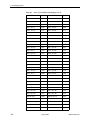
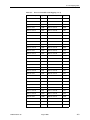
1
Shelf Concentration and Processing (SCP) Card with IP Uplink User’s Guide Document No. 8400-A2-GB21-30 August 2005 Copyright 2005 Paradyne Corporation. All rights reserved. Printed in U.S.A. Notice This publication is protected by federal copyright law. No part of this publication may be copied or distributed, transmitted, transcribed, stored in a retrieval system, or translated into any human or computer language in any form or by any means, electronic, mechanical, magnetic, manual or otherwise, or disclosed to third parties without the express written permission of Paradyne Corporation, 8545 126th Avenue North, P.O. Box 2826, Largo, Florida 33779-2826. Paradyne Corporation makes no representation or warranties with respect to the contents hereof and specifically disclaims any implied warranties of merchantability or fitness for a particular purpose. Further, Paradyne Corporation reserves the right to revise this publication and to make changes from time to time in the contents hereof without obligation of Paradyne Corporation to notify any person of such revision or changes. Changes and enhancements to the product and to the information herein will be documented and issued as a new release to this manual. Warranty, Sales, Service, and Training Information Contact your local sales representative, service representative, or distributor directly for any help needed. For additional information concerning warranty, sales, service, repair, installation, documentation, training, distributor locations, or Paradyne worldwide office locations, use one of the following methods: Internet: Visit the Paradyne World Wide Web site at www.paradyne.com. (Be sure to register your warranty at www.paradyne.com/warranty.) Telephone: Call our automated system to receive current information by fax or to speak with a company representative. — Within the U.S.A., call 1-800-795-8004 — Outside the U.S.A., call 1-727-530-2340 Trademarks Acculink, ADSL/R, Bitstorm, Comsphere, DSL the Easy Way, ETC, Etherloop, FrameSaver, GranDSLAM, GrandVIEW, Hotwire, the Hotwire logo, iMarc, Jetstream, MVL, NextEDGE, Net to Net Technologies, OpenLane, Paradyne, the Paradyne logo, Paradyne Credit Corp., the Paradyne Credit Corp. logo, Performance Wizard, ReachDSL, StormPort, TruePut are registered trademarks of Paradyne Corporation. Connect to Success, Hotwire Connected, JetFusion, JetVision, MicroBurst, PacketSurfer, Quick Channel, Reverse Gateway, Spectrum Manager, and StormTracker are trademarks of Paradyne Corporation. All other products or services mentioned herein are the trademarks, service marks, registered trademarks, or registered service marks of their respective owners. Document Feedback We welcome your comments and suggestions about this document. Please mail them to Technical Publications, Paradyne Corporation, 8545 126th Ave. N., Largo, FL 33773, or send e-mail to [email protected]. Include the number and title of this document in your correspondence. Please include your name and phone number if you are willing to provide additional clarification. A August 2005 8400-A2-GB21-30 Contents About This Guide 1 2 Document Purpose and Intended Audience . . . . . . . . . . . . . . . . . . . . iii Document Summary . . . . . . . . . . . . . . . . . . . . . . . . . . . . . . . . . . . . . . iv Product-Related Documents . . . . . . . . . . . . . . . . . . . . . . . . . . . . . . . . v About the SCP Card Overview . . . . . . . . . . . . . . . . . . . . . . . . . . . . . . . . . . . . . . . . . . . . . . . 1-1 Features . . . . . . . . . . . . . . . . . . . . . . . . . . . . . . . . . . . . . . . . . . . . . . . . 1-2 Accessing the Web Interface Using the Default Management Address . . . . . . . . . . . . . . . . . . . . . . . 2-1 Setting the Management Address Using the CLI . . . . . . . . . . . . . . . . . 2-2 Setting the Management Address for Inband and Out-of-Band Management. . . . . . . . . . . . . . . . . . . . . . . . . . . . . . . . . . . . . . . . . . . . . . . . 2-2 3 4 5 Using the Web Interface. . . . . . . . . . . . . . . . . . . . . . . . . . . . . . . . . . . . 2-3 Configuring Management Overview . . . . . . . . . . . . . . . . . . . . . . . . . . . . . . . . . . . . . . . . . . . . . . . 3-1 Management Guidelines . . . . . . . . . . . . . . . . . . . . . . . . . . . . . . . . . . . 3-1 Management Example . . . . . . . . . . . . . . . . . . . . . . . . . . . . . . . . . . . . . 3-2 Traffic Profiles and DSL Connections Setting Up Default Connections . . . . . . . . . . . . . . . . . . . . . . . . . . . . . . 4-1 Setting Up Traffic Profiles . . . . . . . . . . . . . . . . . . . . . . . . . . . . . . . . . . 4-2 Creating Traffic Profiles . . . . . . . . . . . . . . . . . . . . . . . . . . . . . . . . . 4-2 Modifying a Traffic Profile . . . . . . . . . . . . . . . . . . . . . . . . . . . . . . . 4-4 Configuration - Bridge Connection . . . . . . . . . . . . . . . . . . . . . . . . . . . . 4-5 VLAN Basics . . . . . . . . . . . . . . . . . . . . . . . . . . . . . . . . . . . . . . . . . . . . 5-1 VLAN Tagging . . . . . . . . . . . . . . . . . . . . . . . . . . . . . . . . . . . . . . . . 5-1 VLANs 8400-A2-GB21-30 August 2005 i Contents 6 7 Configuring VLANs. . . . . . . . . . . . . . . . . . . . . . . . . . . . . . . . . . . . . . . . 5-2 Creating a VLAN . . . . . . . . . . . . . . . . . . . . . . . . . . . . . . . . . . . . . . 5-2 Multicasting and Video Applications. . . . . . . . . . . . . . . . . . . . . . . . . . . 6-1 Configuration - Multicast Common Parameters . . . . . . . . . . . . . . . . . . 6-2 Configuration - Multicast Port Parameters . . . . . . . . . . . . . . . . . . . . . . 6-3 Overview . . . . . . . . . . . . . . . . . . . . . . . . . . . . . . . . . . . . . . . . . . . . . . . 7-1 Status - ATM Statistics . . . . . . . . . . . . . . . . . . . . . . . . . . . . . . . . . . . . . 7-2 Status - DSL Performance . . . . . . . . . . . . . . . . . . . . . . . . . . . . . . . . . . 7-3 Status - DSL Statistics . . . . . . . . . . . . . . . . . . . . . . . . . . . . . . . . . . . . . 7-4 Status - Ethernet Performance. . . . . . . . . . . . . . . . . . . . . . . . . . . . . . . 7-6 Status - IMA Performance . . . . . . . . . . . . . . . . . . . . . . . . . . . . . . . . . . 7-9 Status - IMA Statistics . . . . . . . . . . . . . . . . . . . . . . . . . . . . . . . . . . . . . 7-10 Status - Port Rates. . . . . . . . . . . . . . . . . . . . . . . . . . . . . . . . . . . . . . . . 7-12 Status - SHDSL Performance . . . . . . . . . . . . . . . . . . . . . . . . . . . . . . . 7-12 Status - SHDSL Statistics . . . . . . . . . . . . . . . . . . . . . . . . . . . . . . . . . . 7-13 Status - Syslog . . . . . . . . . . . . . . . . . . . . . . . . . . . . . . . . . . . . . . . . . . . 7-14 Status - System Alarms . . . . . . . . . . . . . . . . . . . . . . . . . . . . . . . . . . . . 7-15 Status – Alarms (Detail). . . . . . . . . . . . . . . . . . . . . . . . . . . . . . . . . 7-15 Status - Unknown Cell Log. . . . . . . . . . . . . . . . . . . . . . . . . . . . . . . . . . 7-16 Multicasting Status A Port Mapping Table Index ii August 2005 8400-A2-GB21-30 About This Guide Document Purpose and Intended Audience This guide describes how to configure, operate and troubleshoot the software component of Shelf Concentration and Processing (SCP) cards with an IP uplink. This guide reflects features in the SCP software version 4.2. SCP cards with ATM uplinks are described in the Shelf Concentration and Processing (SCP) Card with ATM Uplink User’s Guide (document number 8400-A2-GB20). Use this guide to: Obtain a basic understanding of the SCP card’s functionality Learn how to configure and monitor the SCP card Create and use VLANs This guide is intended for administrators and operators responsible for network operations. A basic understanding of internetworking protocols and their features is assumed. Specifically, you should have familiarity with the following internetworking concepts: ATM TCP/IP IP routing (also referred to as IP forwarding) It is assumed that you have already installed the Broadband Loop Carrier (BLC), the SCP card, and, if used, the Management Communications Processor (MCP) card. NOTE: You should use this document in conjunction with the appropriate DSL Card User’s Guide. These documents provide information about specific DSL cards you have installed in the BLC. See Product-Related Documents. 8400-A2-GB21-30 August 2005 iii About This Guide Document Summary iv Section Description Chapter 1, About the SCP Card Provides an overview of the features and functionality of the SCP card. Chapter 2, Accessing the Web Interface Explains how to assign an address with the command line interface so that the web interface can be used to configure the BLC. Chapter 3, Configuring Management Explains how to configure inband and out-of-band management. Chapter 4, Traffic Profiles and DSL Connections Explains how to define traffic profiles and how to create virtual circuits. Chapter 5, VLANs Explains how to create and use VLANs. Chapter 6, Multicasting Explains the use and configuration of multicasting and IGMP parameters. Chapter 7, Status Lists the various status screens available for the SCP card and its associated line cards. Appendix A, Port Mapping Table Shows the VPI/VCI default values assigned to circuits on the port card and the SCP card for user data (UBR) service. Index Lists key terms, acronyms, concepts, and sections in alphabetical order. August 2005 8400-A2-GB21-30 About This Guide Product-Related Documents Document Number Document Title 8400-A2-GB20 Shelf Concentration and Processing (SCP) Card with ATM Uplink User’s Guide 8400-A2-GT20 GranDSLAM 3.x (SCP Card with ATM Uplink) Training Guide 8400-A2-GT21 GranDSLAM 4.x (SCP Card with IP Uplink) Training Guide 8400-A2-GZ40 Shelf Concentration and Processing (SCP) Card Installation Instructions 8620-A2-GN20 8620 Broadband Loop Carrier Installation Guide 8700-A2-GB20 Hotwire TDM SDSL Termination Units, Models 8777 and 8779, User's Guide 8700-A2-GB25 Hotwire TDM SDSL Termination Units, Models 8775 and 8785, User's Guide 8799-A2-GB20 Hotwire 8799 TDM SHDSL Line Card, with G.703 Interface, User's Guide 8820-A2-GN20 8820 Broadband Loop Carrier Installation Guide 8900-A2-GB20 ATM Line Cards, Models 8955, 8965, 8968, 8975, and 8985, User’s Guide 8922-A2-GN10 8922 POTS Card Installation and User's Guide 8990-A2-GN10 T1 and E1 IMA Cards, Models 8995 and 8997, Installation and User’s Guide To order a Paradyne document or to speak with a sales representative, please call 1-727-530-2000. Paradyne documents are also available on the World Wide Web at www.paradyne.com. Select Support → Technical Manuals. 8400-A2-GB21-30 August 2005 v About This Guide vi August 2005 8400-A2-GB21-30 About the SCP Card 1 Overview The Shelf Concentration and Processing (SCP) card is a circuit card assembly that comprises a parent card with an ATM switch, a backplane interface, a processor, a cell multiplexer/demultiplexer, and an uplink childcard. The childcard determines the type of uplink supported by the SCP card. When the SCP card is used in an 8620 or 8820 Broadband Loop Carrier (BLC), it aggregates DSL traffic from each of the DSL port cards in the chassis on the BLC’s backplane bus and concentrates it onto an IP interface. The SCP card supports the following line cards: 8922 POTS Line Card 8965 and 8968 ADSL2+ ATM Cards 8975 ReachDSL®+ ATM Card 8985 SHDSL ATM Card 8995 T1 IMA Card 8997 E1 IMA Card With a Management Control Processor (MCP) card installed in the same chassis, the SCP card also supports Time Division Multiplexer (TDM) SDSL and SHDSL cards, Models 8775, 8777, 8779, and 8799. 8400-A2-GB21-30 August 2005 1-1 1. About the SCP Card Features The SCP card provides these features: Command Line Interface (CLI) The SCP card supports a router-like command line interface using Telnet or an attached console. Web Interface The SCP card supports a web interface through Internet Explorer Version 6 or above. Network Management Support via SNMP The SCP card supports primary network management support through an SNMP agent for configuring, monitoring, and sending traps. Monitoring Monitoring screens let you monitor the activity of the SCP card. Diagnostics Test and status screens let you diagnose uplink and card problems, and perform and review results of tests (including power-on self-test). Alarm Indications Faceplate LEDs and web interface screens provide card status. Non-Volatile Database Storage The SCP card has non-volatile database storage for configuration options and cross connections. Control Firmware download, configuration upload and download. Management Router Provides the capability of managing an external device connected to the SCP card’s Ethernet port, in addition to inband management capabilities already present in the BLC. VLANs The SCP card supports up to 4095 VLANs. 1-2 August 2005 8400-A2-GB21-30 Accessing the Web Interface 2 Using the Default Management Address The SCP card supports a router-like Command Line Interface (CLI). The CLI can be used to configure and maintain the system, but the web interface is recommended. You can access the web interface using the default management address or a network address you specify using the CLI (see Setting the Management Address Using the CLI on page 2-2). Procedure To use the default management address: 1. Connect a PC to the LAN SCM port of the 8620 BLC or the LAN Slot A or B port (depending on which slot the SCP card is in) of the 8820 BLC using a crossover cable. 2. Access the web interface by typing the default address 10.10.10.10 into the Location field of your web browser. See Using the Web Interface on page 2-3. 8400-A2-GB21-30 August 2005 2-1 2. Accessing the Web Interface Setting the Management Address Using the CLI The management address can be set using the CLI. Procedure To set the management address of the SCP card using the CLI: 1. Using the supplied cable and DB9 adapter, connect a PC with a terminal emulation program to the SERIAL SCM jack of your BLC. This gives you access to the CLI. 2. Log in to the SCP card using: Login> SUPERUSER Password> ASN#1500 The password appears on the screen as asterisks. The startup procedure differs depending on the type of management used: Inband Management – Operates over the uplink. Out-of-Band Management – Operates over the LAN SCM port (8620) or LAN Slot A or B (8820) Setting the Management Address for Inband and Out-of-Band Management Procedure To start up the SCP using both inband and out-of-band management: 1. Specify the uplink port using the configure uplink command. The uplink must be either eth1 or eth2. For example: PDYN# configure uplink eth1 2. Assign an inband management IP address, subnet mask, and next-hop router using the configure management command. For example: PDYN# configure management inband address 137.90.127.3 255.255.255.0 PDYN# configure management default-gateway 137.90.127.1 3. Assign an out-of-band management IP address and subnet mask using the configure management command. For example: PDYN# configure management out-of-band address 137.90.126.1 255.255.255.0 Do not configure inband and out-of-band management on the same subnet. You can now access the web interface by typing into the Location field of your web browser the IP address assigned to the Ethernet port. See Using the Web Interface on page 2-3. 2-2 August 2005 8400-A2-GB21-30 2. Accessing the Web Interface Using the Web Interface To access the web interface: Procedure 1. Start Internet Explorer (Version 6 or above). 2. Type http:// and the IP address of the SCP card into the Address field of your browser window. The default address is 10.10.10.10: Your PC must be in the same subnet as the SCP card, or have routed access to the subnet. 3. A login window appears. Enter the default User ID (SUPERUSER) and Password (ASN#1500), and click on OK. The web interface screen appears. 4. Click on the menu tab appropriate to what you would like to do: — Configuration – To configure the system and interfaces — Status – To display statistics, status, and contents of memory — System – To display system information, download firmware, back up configurations, and modify users — Tests – To start and stop tests The web interface has an integral Help system. Click on the Help icon ( on any screen to invoke a related Help. 8400-A2-GB21-30 August 2005 ) 2-3 2. Accessing the Web Interface 2-4 August 2005 8400-A2-GB21-30 Configuring Management 3 Overview The SCP card supports management data over an uplink port (inband) and over the Ethernet port (out-of-band). Either management type can be configured using the web interface. To configure management addresses using the CLI, see Setting the Management Address Using the CLI in Chapter 2, Accessing the Web Interface. As used in this guide: An Ethernet managed device is a device connected to the SCP card’s Ethernet port. A managed endpoint is an endpoint attached to a line card in the BLC, which is managed via the SCP's inband management connection. Management Guidelines The following guidelines apply to management using an SCP card: 8400-A2-GB21-30 If an MCP is present, the MCP's IP address can be on the same or a different subnet than the SCP card's inband management IP address. The SCP card's out of band management IP address must be on a different subnet than the SCP card's inband management IP address. Managed endpoint IP addresses can be on the same or a different subnet than the SCP card's inband management IP address. Managed endpoint IP addresses must be added to the ATM Management PVC Screen and ATM-1 or ATM-2 must be enabled in the IP Port screen (even if inband management is not being used) in order to be accessed. Ethernet managed devices that are on a different subnet than the SCP card's Ethernet subnet require a route to be added to the routing table. Ethernet managed devices that are on the same subnet as the SCP card's Ethernet subnet do not need a route to be added to the routing table. August 2005 3-1 3. Configuring Management Management Example In the following example: The SCP card and Ethernet managed devices are on a different subnet than the SCP card’s ATM-1 port. A remote network is accessible through Remote Device 1. Endpoints support network management. SHDSL Slot 10 Port 1 8820 BAC Core Router 10.100.88.2 255.255.255.252 POWER A Ethernet Managed Device 3 10.100.94.3 255.255.255.0 Fan Major Minor DISCONNECTED AT THE SOURCE BEFORE REMOVING OR INSTALLING THIS PWR ENTRY MODULE POWER ENTRY MODULE LEFT UNIT: LINE A RIGHT UNIT: LINE B 48V NEG 48V RTN POWER ENTRY MODULE LEFT UNIT: LINE A RIGHT UNIT: LINE B WARNING! POWER MUST BE 48V NEG SCP Card 48V RTN SCP Card ATM-1 Port 10.100.88.1 255.255.255.252 ALARMS B CLOCK SERIAL AC A MCC ALARM 2 4 6 8 B SERIAL ALARM CLOCK SMCM 1 3 5 7 LAN/WAN SLOT A 10 12 14 16 18 11 13 15 17 Managed SHDSL Endpoint 10.100.96.217 WARNING! POWER MUST BE DISCONNECTED AT THE SOURCE BEFORE REMOVING OR INSTALLING THIS PWR ENTRY MODULE 9 B SCP Card Ethernet Port 10.100.94.254 255.255.255.0 Ethernet Managed Device 2 10.100.94.2 255.255.255.0 Ethernet Managed Device 1 10.100.94.1 255.255.255.0 RemoteDevice 1 10.100.95.254 255.255.255.0 04-17457-01 3-2 August 2005 8400-A2-GB21-30 3. Configuring Management Procedure To configure management: 1. Select Configuration > Management > IP Port. The Configuration - IP Port screen appears. Select an ATM port from the drop-down list to configure inband management. ATM management PVCs terminated on the SCP card are routed encapsulated (RFC 1483) PVCs. 2. Enter or select: Field Description Configuration Mode Select the configuration mode for the IP port from the drop-down list: MANUAL – Port parameters are configured by the operator. DHCP – Port parameters are configured using the Dynamic Host Configuration Protocol. 8400-A2-GB21-30 IP Address Specify the IP address associated with the port. This is required if Configuration Mode is Manual. Network Mask Specify the subnet mask associated with the IP address. This is required if Configuration Mode is Manual. For ATM-1 and ATM-2, the value must be 255.255.255.255. VLAN ID Specify the VLAN ID of the port. Port Status Specify the administrative state of the port by selecting Enable or Disable from the drop-down list. MAC Address This display-only field shows the hardware address of the port. August 2005 3-3 3. Configuring Management Field Description DHCP Slot Select the Slot. The Slot field is accessible if an ATM port is selected and Configuration Mode is DHCP DHCP Port Select the Port. The Port field is accessible if an ATM port is selected and Configuration Mode is DHCP. DHCP VPI Enter the ATM Virtual Path Identifier (0-15). The ATM VPI and VCI fields are accessible if an ATM port is selected and Configuration Mode is DHCP. DHCP VCI Enter the ATM Virtual Channel Identifier (32-1023). The ATM VPI and VCI fields are accessible if an ATM port is selected and Configuration Mode is DHCP. 3. Click on Apply. 4. Select Enet_mgmt from the Port drop-down list. Enter the IP Address and Network Mask for out-of-band management. 5. Click on Apply. 6. To create a route to a remote device, select Configuration > Management > ATM Mgmt PVC. The Configuration - ATM Management PVC screen appears. 7. Click on Create New Entry. The Configuration - ATM Management PVC Create screen appears. 3-4 August 2005 8400-A2-GB21-30 3. Configuring Management 8. Enter or select: Field Description Slot Select a Slot from the drop-down list. Port Select a Port from the drop-down list. IP Port Select an IP Port from the drop-down list: ATM-1 - First IP-over-ATM interface ATM-2 - Second IP-over-ATM interface Next Hop IP Address Enter the next-hop IP address associated with the endpoint. It must be on a different subnet than the ATM port. ATM VPI Enter the ATM Virtual Path Identifier (0–15) associated with the virtual circuit for the entry. ATM VCI Enter the ATM Virtual Channel Identifier (32–1023) associated with the virtual circuit for the entry. 9. Click on Apply. The new PVC is listed under PVC Entries on the Configuration - ATM Management PVC screen. 10. Use the Configuration - IP Route Create screen to create a route to a remote device. Select Configuration > Management > IP Routing. The Configuration IP Routing screen appears. 8400-A2-GB21-30 August 2005 3-5 3. Configuring Management 11. Click on Create New IP Route. The Configuration - IP Route Create screen appears. 12. Enter the Destination, Subnet Mask, and Gateway. 13. Click on Apply. 3-6 August 2005 8400-A2-GB21-30 Traffic Profiles and DSL Connections 4 Setting Up Default Connections The SCP card is designed to minimize the work of configuration by providing useful defaults. Procedure To set up the SCP card with default connections: 1. Determine the expected services to be deployed from the BLC and identify the attributes of these service offerings (such as ATM Class of Service, sustained peak cell rates, and subscriber oversubscription targets). 2. Using the information gathered in Step 1, determine the traffic management strategy for handling congestion in the BLC and the network (such as policing). 3. Select the profiles to match the predominant service profile using the Configuration - Profile Traffic Descriptor screen. See Setting Up Traffic Profiles on page 4-2. 4. Determine the VPI/VCI numbering strategy. It is recommended for ease of administration and maintenance that default VCs with different traffic profiles be configured on separate VPIs. 5. Based on the intended services, determine what type of port cards will be installed in the chassis and how many default connections they require: — Packet port cards and cell port cards have one default data VC per port. — TDM port cards (such as TDM SDSL) do not use the SCP card and require no default VCs. 6. Use the Configuration - DSL Connection screen to associate DSL ports with ATM connections and VLANs. See Configuration - Bridge Connection on page 4-5. 8400-A2-GB21-30 August 2005 4-1 4. Traffic Profiles and DSL Connections Setting Up Traffic Profiles Traffic Profiles are required for all connections to allow the SCP card to perform its traffic management functions such as Connection Admission Control (CAC). You can define up to 250 traffic profiles for the SCP card using the Configuration Profile Traffic Descriptor screen. Traffic profiles specify the traffic class of the connection and the expected sustained and peak cell rates (SCR and PCR), as well as the Maximum Burst Size (MBS). It is recommended for ease of administration that the same traffic profile be used on both the SCP card and the ATM line cards. The same set of traffic profiles should be shared among all ATM line cards in the chassis, and the whole DSL network, if possible. Creating Traffic Profiles Procedure To create a traffic profile: 1. On the Configuration menu tab, select ATM > Profile. The Configuration Profile Traffic Descriptor screen appears. 4-2 August 2005 8400-A2-GB21-30 4. Traffic Profiles and DSL Connections 2. Click on Create New Profile. The first Configuration - Profile Traffic Descriptor Create screen appears. 3. Select a Class of Service (CoS) from the drop-down list: — UBR (Unspecified Bit Rate) — CBR (Constant Bit Rate) — nrt-VBR (Non-Real-Time Variable Bit Rate) — rt-VBR (Real-Time Variable Bit Rate) Click on Select. The Configuration - Profile Traffic Descriptor Create - CoS screen appears, where CoS is the class of service you selected. 8400-A2-GB21-30 August 2005 4-3 4. Traffic Profiles and DSL Connections 4. What fields are displayed depends on the Class of Service. Enter or select: Field Description Profile Name Enter a name for this profile. PCR Enter a Peak Cell rate from 0 to 351566. SCR Enter a Sustainable Cell Rate from 0 to 351566. CDVT Enter a Cell Delay Variation Tolerance from 0 to 100000. MBS Enter a Maximum Burst Size from 0 to 351566. Tagging Select Yes or No from the drop-down list to determine if tagging is allowed for this profile. Traffic Policing Select Yes or No from the drop-down list to determine if traffic policing is allowed for this profile. Packet Discard Select Yes or No from the drop-down list to determine if partial packet discards are allowed for this profile. Shaping Select Yes or No from the drop-down list to determine if shaping is allowed for this profile. 5. Click on Apply. Modifying a Traffic Profile Procedure To modify a traffic profile: 1. On the Configuration - Profile Traffic Descriptor screen, click in the selection box next to the profile you want to modify. 2. Click on Modify Selected. The Configuration - Profile Traffic Descriptor Modify screen appears. 3. Modify the fields as required. 4. Click on Apply. 4-4 August 2005 8400-A2-GB21-30 4. Traffic Profiles and DSL Connections Configuration - Bridge Connection Use the Configuration - Bridge Connection Create screen to associate DSL ports with ATM connections and VLANs. To define bridge connections: 1. From the main menu, select Configuration > Bridge > Connections. The Configuration - Connections - Menu screen appears. 2. Click on Create Connection. The Configuration - Bridge Connection Create screen appears. 3. Select a Slot and Port from the drop-down lists. 4. ATM fields are omitted for cards to which they are not applicable. If present, enter or select the following ATM parameters: Field Description VPI Specify the path (0–15) for this connection. VCI Specify the channel (32–255) for this connection. Encapsulation Select an ATM encapsulation protocol from the drop-down list: llc-bridged – Logical Link Control bridged. The protocol of a packet is identified in an LLC header. llc-pppoa – Logical Link Control PPP (Point to Point Protocol) Over ATM (Asynchronous Transfer Mode). The protocol of a packet is identified in an LLC header. vcm-bridged – Virtual Channel Multiplexing bridged. A separate VC is used for each higher level protocol. vcm-pppoa – Virtual Channel Multiplexing PPP Over ATM. A separate VC is used for each higher level protocol. 8400-A2-GB21-30 August 2005 4-5 4. Traffic Profiles and DSL Connections Field Description Ingress Profile Select the ATM profile for inbound traffic from the drop-down list. Egress Profile Select the ATM profile for outbound traffic from the drop-down list 5. Enter or select the following Bridge parameters: Field Description PVID Specify the Port VLAN ID to be applied to untagged frames received from the CPE on the DSL port over this connection. Any VLAN ID (1–4094) of a previously configured user VLAN may be used. 802.1p Priority Specify a non-zero value (1–7) to cause frames to be tagged according to this 802.1p priority. 1 is the lowest priority and 7 the highest. Queueing Method Specify whether frames received in a downstream direction are queued according to their 802.1p priority, or handled on a first-in, first-out (FIFO) basis. If the queuing method is set to 802.1p, the priority is assessed on a per PVC basis and not between PVCs. Acceptable Frame Type Specify what type of frames will be accepted from the LAN on this port. Unacceptable frames will be dropped. Tagged – Only VLAN tagged frames will be accepted All – Both VLAN tagged and untagged frames will be accepted Ingress Filter Enabled Specify if frames from the LAN with VLAN tags that are not members of this port should be filtered out and discarded. Checked (enabled) - Frames that are not members of a VLAN on this port will be dropped. Unchecked (disabled) - All frames are accepted. Role Specify the role of the connection: Subscriber Network Maximum Number Specify the maximum number of MAC addresses permitted to of MAC Addresses access the selected port. 4-6 August 2005 8400-A2-GB21-30 4. Traffic Profiles and DSL Connections 6. Enter or select the following Egress VLAN parameters: Field Description VLAN List Select a VLAN or multiple VLANs. To select a VLAN while retaining previous VLAN selections, press the CTRL key as you click on a VLAN. To select a range of VLANs, select one VLAN, position the cursor some number of VLANs above or below your selection, then click on a VLAN while holding down the Shift key. Click on Select All to select all listed VLANs, and click on Clear All to remove any selections you have made. Egress Tag Select the egress tag for the selected VLAN or VLANs: Tagged Untagged 7. Click on Add to add the selected VLAN or VLANs to the Assigned VLAN/Egress Tag list box. 8. Enter or select the following IP Filters parameters: Field Description Address Specify an IP address to be filtered on the selected ports. Mask Specify the subnet mask of the IP address. 9. Click on Add to add the Address and Mask to the Currrent Filters list box. 10. Click on Create New Connection. 8400-A2-GB21-30 August 2005 4-7 4. Traffic Profiles and DSL Connections 4-8 August 2005 8400-A2-GB21-30 VLANs 5 VLAN Basics VLANs (Virtual Local Area Networks) allow multiple logical interfaces on a single physical interface. The devices on a VLAN communicate as if they were on the same physical LAN. This technique segregates the traffic between multiple users. So even though multiple users are on a common interface, they are not aware of each other, and each user appears to own the entire interface. Devices within each VLAN can only communicate with member devices in the same VLAN. VLANs can also be used to segregate the types of traffic. For example, a network might have a VLAN for data, another VLAN for voice traffic, and another VLAN for video. VLANs benefit the network provider in that VLANs help control traffic. With traditional local area networks, congestion can be caused by broadcast traffic that is directed to all devices. VLANs increase the efficiency of a network because each VLAN can be set up to contain only those devices that must communicate with each other. Therefore, broadcasts are sent only to devices that need the broadcast information. This is referred to as a common broadcast domain. VLAN Tagging VLANs are based on the IEEE 802.3Q standard. VLAN tagging is a process that inserts a VLAN tag into the Ethernet frame. The tag contains the identification number of a specific VLAN, which is called the VLAN ID, and a priority field. Not all ports in a VLAN must be tagged. Ports can be untagged members of a VLAN. As traffic for a port is forwarded out of the switch, the unit determines if the port should use tagged or untagged packet formats for that VLAN. The switch adds or deletes tags, as required, for each port that is configured for the VLAN. 8400-A2-GB21-30 August 2005 5-1 5. VLANs Configuring VLANs VLAN Configuration is a two-part process. The first step is to create the VLAN and the second step is to define how each port should handle VLANs. Creating a VLAN Use the Configuration - VLAN Create screen to create a new VLAN. To create a new VLAN: 1. Select Configuration > Bridge > VLAN. The Configure - VLAN screen appears, displaying any VLANs already configured. 2. To create a VLAN, click on Add New VLAN. The Configuration - VLAN - Create screen appears. 5-2 August 2005 8400-A2-GB21-30 5. VLANs 3. Enter or select the following parameters. Field Description VLAN ID Specify a unique VLAN ID for the VLAN. It may be any unused ID from 2 to 4094. For example: 22 Name Specify a unique name for the VLAN up to 32 characters. This can be used to refer to the VLAN by name instead of the VLAN ID if desired. For example: ISP1 Secure Mode Specify if Secure Mode is enabled or disabled for this VLAN: Enabled – All traffic from the DSL ports on this VLAN is sent only to the designated uplink port. Clients on DSL ports cannot connect directly to each other or see any data from any other user within the unit on this VLAN. Disabled – The unit behaves like a basic switch on this VLAN. Broadcasts from a DSL port are visible to all other DSL ports and clients on DSL ports may make direct connections to each other. 8400-A2-GB21-30 Proxy ARP Specify whether Proxy ARP is enabled. Next Hop Router Specify the default next-hop router. Secure Uplink Selection Select the secure uplink slot and group from the drop-down list. August 2005 5-3 5. VLANs Field Description DHCP Option 82 Specify whether DHCP Option 82 is enabled or disabled for this VLAN: Enabled – The BLC adds DHCP Option 82 information to DHCP requests entering the BLC from subscriber links and bound for the uplink, and strips the DHCP Option 82 information from DHCP responses entering the BLC from the uplink and bound for subscriber links. The Circuit Identifier field of the DHCP Relay Agent Information Option circuit identifier suboption includes: The system name configured for the chassis The BLC slot and subscriber port The DSL port VPI and VCI The VLAN to which this PVC is assigned The decimal MIB II ifIndex value for the DSL port If supported by the endpoint, the Circuit Identifier field of the DHCP Relay Agent Information Option agent remote identifier suboption includes: The serial number of the endpoint The endpoint vendor identifier Do not enable Option 82 unless you are certain your DHCP server supports Option 82. Disabled – The BLC does not process DHCP Option 82 information. 4. Click on Create and Display VLAN Port Configuration. Ports are associated with VLANs using the Configuration - Bridge Connection screens. See Configuration - Bridge Connection in Chapter 4, Traffic Profiles and DSL Connections. 5-4 August 2005 8400-A2-GB21-30 Multicasting 6 Multicasting and Video Applications The SCP card supports up to 255 multicast streams. Each multicast stream may represent a separate video content channel coming into the BLC, having been requested by at least one video customer. All customers can have access to the channels by joining and leaving the multicast groups. In the downstream direction, a DSL port PVC is mapped to a multicast stream, rather than to a particular set-top box or MAC address. Up to three simultaneous multicast streams can be deployed on a DSL port used to provide a video service. On a DSL port that delivers video service, a PVC must be configured to act as the IGMP control upstream for all the multicast channels. For delivery of n multicast streams, n+1 PVCs must be configured over the DSL interface. For example, if the service is guaranteed to support two set top boxes (two simultaneous video streams), two multicast PVCs and one unicast PVC must be configured on the DSL link. An ATM profile may be applied to the multicast PVCs and it is recommended that nrt-VBR be used as the ATM class of service. A video-specific ATM profile can be defined for this purpose and applied to each multicast PVC as it is provisioned. This allows prioritization of the video traffic above the Internet traffic, assuming that Internet traffic uses an ATM UBR profile. The PVC used for upstream control information will typically be UBR. The endpoint must be configured for RFC 1483/2864 Bridged Encapsulation on all PVCs, even those over which it is routing. A bridge must be configured on the endpoint for all multicast traffic, including: The downstream multicast PVCs The control PVC The Ethernet ports to which the set-top boxes are attached It is recommended that Internet traffic be routed or handled by a separate bridge than the multicast traffic so that it can have lower priority. However, if the internet traffic is configured in the BLC to share the multicast control PVC, it must share the same bridge as the multicast traffic. If the endpoint provides an IAD (Integrated Access Device) function or if an MTA (Media Terminal Adapter) is connected to an Ethernet port on the endpoint, the endpoint should be configured such that voice traffic is carried on a dedicated PVC of highest priority. 8400-A2-GB21-30 August 2005 6-1 6. Multicasting Configuration - Multicast Common Parameters Use the Configuration - Multicast Common Parameters to establish the general rules for IGMP snooping and proxy. Procedure To set multicast parameters: 1. Enter or select the following fields: Field Description Snooping Specify the state of IGMP snooping: Disabled - The unit will not recognize multicast packets. Enabled – IGMP Snooping is enabled. The unit will process multicast packets and snoop IGMP packets to learn multicast group address and port associations. IGMP Proxy Specify the state of IGMP Proxy: Disabled - The unit will relay all IGMP messages and not perform any proxy functions. Enabled – The unit will act as an IGMP querier if needed. In addition the proxy function will perform quick query functions that allows a smooth changing of data streams. The IGMP Snooping function must also be enabled for this function to be enabled. 2. Click on Apply. 6-2 August 2005 8400-A2-GB21-30 6. Multicasting Configuration - Multicast Port Parameters Use the Configuration - Multicast Port Parameters screen to set port-specific parameters for multicasting. The following illustration shows the relationship of IGMP snooping parameters. STB (Set-Top Box) to/from BAC Join A Query for A Leave A Query for A Join B Stream A Stream B 04-17460-01 From BAC to Upstream Leave Delay Parameter Send Join B Send Leave A and Stop Old Stream Start New Stream Quick Query Wait Time Parameter Leave - Join Forwarding Delay Parameter Procedure To set multicast port parameters: 1. Select a Slot from the drop-down list. 2. Select a Port from the drop-down list. 3. Enter or select the following fields: Field Description Quick Query Count Specify the number of Quick Queries to a port that will be generated in response to an IGMP Leave Message on that port. If no responses are received after this number of messages then it can be assumed that no subscribers on that port want to be in the multicast group. This parameter is also referred to as the robustness value. The default is 2. The valid range is 1 to 10. 8400-A2-GB21-30 August 2005 6-3 6. Multicasting Field Description Leave Delay Specify the amount of time, in tenths of a second, that the multicast stream will continue on a port after the receipt of a leave message. The default value is 3 (0.3 seconds). The valid range is 0 to 255 (0 to 25.5 seconds). Leave-Join Delay Specify the amount of time, in tenths of a second, that the start of a new multicast stream on a port is delayed following the receipt of a leave message. The default value is 3 (0.3 seconds). The valid range is 0 to 255 (0 to 25.5 seconds). Multicast Group 1 VPI/VCI Specify the connection for the first multicast group. Multicast Group 2 VPI/VCI Specify the connection for the second multicast group. Multicast Group 3 VPI/VCI Specify the connection for the third multicast group. ATM Profile Select a profile to be applied to this port from the drop-down list. ATM Encapsulation Select the encapsulation protocol to be used: llc-bridged – Logical Link Control bridged. The protocol of a packet is identified in an LLC header. vcm-bridged – Virtual Channel Multiplexing bridged. A separate VC is used for each higher level protocol. 4. Click on Apply. 6-4 August 2005 8400-A2-GB21-30 Status 7 Overview The SCP card’s web interface provides many status screens that show the state, performance, and statistics for the uplink and DSL line cards. 8400-A2-GB21-30 Status - ATM Statistics on page 7-2 Status - DSL Performance on page 7-3 Status - DSL Statistics on page 7-4 Status - Ethernet Performance on page 7-6 Status - IMA Performance on page 7-9 Status - IMA Statistics on page 7-10 Status - Port Rates on page 7-12 Status - SHDSL Performance on page 7-12 Status - SHDSL Statistics on page 7-13 Status - Syslog on page 7-14 Status - System Alarms on page 7-15 Status - Unknown Cell Log on page 7-16 August 2005 7-1 7. Status Status - ATM Statistics Use the ATM Statistics screen to view the number of uncorrectable HEC errors. To display ATM statistics: 1. Select Status > Statistics > ATM. The Status - ATM Statistics screen appears. 2. Select a port from the drop-down list. 3. Select a slot from the drop-down list. 4. Select an interval type: — 15 Minutes – For the last 15-minute interval — 30 Minutes – For the last two 15-minute intervals — 1 Hour – For the last four 15-minute intervals — 96 Intervals – For the last day's 15-minute intervals — 1 Day Total – For the total of the last 96 15-minute intervals 5. Click on Refresh to display the latest count. 7-2 August 2005 8400-A2-GB21-30 7. Status Status - DSL Performance Use the DSL Performance screen to obtain performance statistics for the near-end modem (ATU-C), far-end modem (ATU-R), ATM layer, and ATM PVC. Select Status > Performance > DSL. The Status - DSL Performance screen appears. To display statistics, select a port from the drop-down list. The following information is displayed: Field Description DSL Layer Performance – Near End Current SNR Margin The noise margin as seen by this ATU with respect to its received signal in tenths of a decibel. Current Loop Attenuation The measured difference in the total power transmitted by the peer ATU and the total power received by this ATU. Current Output Power The measured total output power transmitted by this ATU. Loss of Framing (LOF) There has been a failure due to an invalid frame. Loss of Signal (LOS) The ATU-C detected a loss of signal. Loss of Signal Quality There has been a failure due to loss of signal quality. Loss of signal quality is declared when the Noise Margin falls below the Minimum Noise Margin, or the bit-error-rate exceeds 10–7. Loss of Link The ATU-C was unable to link with the ATU-R. Data Init Failure The ATU-C failed during initialization due to bit errors corrupting startup exchange data. Configuration Init Failure There has been a Configuration Initialization failure. Protocol Init Failure The ATU-C failed during initialization due to an incompatible protocol being used by the peer ATU-R. No Peer ATU Present The ATU-C failed during initialization because no activation sequence was detected from the peer ATU-R. Current Tx Rate The rate of transmission. DSL Layer Performance – Far End 8400-A2-GB21-30 Current SNR Margin The noise margin as seen by this ATU with respect to its received signal in tenths of a decibel. Current Loop Attenuation The measured difference in the total power transmitted by the peer ATU and the total power received by this ATU. Current Output Power The measured total output power transmitted by this ATU. Loss of Framing (LOF) There has been a failure due to an invalid frame. August 2005 7-3 7. Status Field Description Loss of Signal (LOS) There has been a failure due to loss of signal. Loss of Signal Quality There has been a failure due to loss of signal quality. Loss of signal quality is declared when the Noise Margin falls below the Minimum Noise Margin, or the bit-error-rate exceeds 10–7. Current Tx Rate The rate of transmission. ATM Layer Performance Loss of Cell Delineation The number of Loss of Cell Delineation events since the last reset. An LCD state is declared after an OCD condition persists for 4 milliseconds. Cells Sent The number of cells sent since the last reset. Cells Received The number of cells received since the last reset. Received Cells Dropped The number of received cells dropped since the last reset. OCD Events The number of Out of Cell Delineation events since the last reset. An OCD event is declared when seven consecutive ATM cells have Header Error Control (HEC) violations. ATM PVC Performance Cells Sent The number of cells sent on this PVC since the last reset. Cells Received The number of cells received on this PVC since the last reset. Click on Refresh to display the latest information. Status - DSL Statistics Use the DSL Statistics screen to obtain error statistics by DSL port. To display statistics: 1. Select Status > Statistics > DSL. The Status - DSL Statistics screen appears. 2. Select a Slot from the drop-down list. 3. Select a Port from the drop-down list. 4. Select an interval type: — 15 Minutes – For the last 15-minute interval — 30 Minutes – For the last two 15-minute intervals — 1 Hour – For the last four 15-minute intervals — 96 Intervals – For the last day's 15-minute intervals — 1 Day Total – For the total of the last 96 15-minute intervals 7-4 August 2005 8400-A2-GB21-30 7. Status The following information is displayed: Field Description Near End LOFS The number of Loss of Framing failures. LOSS The number of Loss of Signal failures. LOLS The number of Loss of Link failures. ES The number of Errored Seconds. The errored second parameter is a count of one-second intervals containing one or more CRC anomalies, or one or more LOS or Severely Errored Frame (SEF) defects. SES The number of Severely Errored Seconds. UAS The number of Unavailable Seconds. Far End LOFS The number of Loss of Framing failures. LOSS The number of Loss of Framing failures. Loss of Power The number of Loss of Power failures. ES The number of Errored Seconds. The errored second parameter is a count of one-second intervals containing one or more CRC anomalies, or one or more LOS or Severely Errored Frame (SEF) defects. SES The number of Severely Errored Seconds. An SES is a one-second interval during which either 18 or more errored frames were received, or at least one loss of signal defect, severely errored frame defect, or loss of power defect occurred. UAS The number of Unavailable Seconds. The UAS counter starts after 10 consecutive severely errored seconds. 5. Click on Refresh to display the latest information. 8400-A2-GB21-30 August 2005 7-5 7. Status Status - Ethernet Performance Use the Status - Ethernet Performance screen to display the status, error counts, and throughput of Ethernet ports. To display Ethernet performance information, select Status > Performance > Ethernet. The Status - Ethernet Performance screen appears. Select a Port from the drop-down list and click on Select. Field Description Ethernet Layer Status Link Status Shows the status of the link: dormant – The link has no device attached down – The link is administratively down or has a fault that prevents it from coming up unknown – The link’s status cannot be determined up – The link is enabled and ready to send packets Link Up Time Shows the number of days, hours, minutes, and seconds the link has been active. Rate (Mbps) Shows the data rate of the link in Mbps. Duplex Shows the duplex mode: Full – The link is full-duplex Half – The link is half-duplex Connector Type Shows the physical interface used: RJ45 – The interface is the 8-wire modular jack Fiber – The interface is the SFP optic fiber socket Ethernet Layer Status Link Status Shows the status of the link: dormant – The link has no device attached down – The link is down unknown – The link’s status cannot be determined up – The link is enabled and ready to send packets Link Up Time Shows the number of days, hours, minutes, and seconds the link has been active. Rate (Mbps) Shows the data rate of the link in Mbps. Duplex Shows the duplex mode: Full – The link is full-duplex Half – The link is half-duplex 7-6 August 2005 8400-A2-GB21-30 7. Status Field Description Connector Type Shows the physical interface used: RJ45 – The interface is the 8-wire modular jack Fiber – The interface is the SFP optic fiber socket Ethernet Layer Statistics 8400-A2-GB21-30 Total Bytes Received Shows the number of bytes received. Total Bytes Transmitted Shows the number of bytes transmitted. Total Frames Received Shows the number of frames received. Total Frames Transmitted Shows the number of frames transmitted. Unicast Packets Received Shows the number of unicast packets received. Unicast Packets Transmitted Shows the number of unicast messages transmitted. Broadcast Packets Received Shows the number of broadcast packets received. Broadcast Packets Transmitted Shows the number of broadcast messages transmitted. Multicast Packets Received Shows the number of multicast packets received. Multicast Packets Transmitted Shows the number of multicast messages transmitted. Total Frames Discarded Shows the number of frames discarded for any reason. Errored Frames Shows the number of frames detected to be in error. Paused Frames Received Shows the number of pause (flow control) frames received. Paused Frames Transmitted Shows the number of pause (flow control) frames transmitted. Excessive Collisions Shows the number of frames not transmitted due to excessive (15) collisions. Deferred Transmissions Shows the number of frames successfully transmitted after transmission has been deferred at least once. Carrier Sense Errors Shows the number of times the carrier sense signal was lost during transmission. Alignment Errors Shows the number of frames received with an alignment error. FCS Errors Shows the number of frames with Frame Check Sequence (FCS) errors. August 2005 7-7 7. Status Field Description Single Collision Frames Shows the number of frames transmitted after a single collision. Multiple Collision Frames Shows the number of frames transmitted after multiple collisions. SQE Test Errors Shows the number of Signal Quality Error (SQE) test errors received. Late Collisions Shows the number of collisions detected after the normal window. Internal MAC Receive Errors Shows the number of frames dropped on reception because of Media Access Control (MAC) errors. Internal MAC Transmit Errors Shows the number of frames dropped on transmission due to MAC errors. Frame Too Longs Shows the number of frames dropped because they exceeded the maximum Ethernet frame size. Symbol Errors Shows the number of symbols received that could not be decoded. Click on Refresh to update the statistics. 7-8 August 2005 8400-A2-GB21-30 7. Status Status - IMA Performance Use the Status - IMA Performance screen to view failure status, cell rate, and cell counts for an IMA group. To view IMA performance: 1. Select a Slot from the drop-down list. 2. Select an IMA Group from the drop-down list. 3. Scroll through the frame, or click on Links, ATM Layer, or PVCs to jump to an area of particular interest. 4. The following information is displayed: Field Description IMA Group n: Fail Status The current group failure status: No Failures, Start-up, Invalid M Value, Insufficient Links, Blocked, Other, or Invalid IMA Version. NE State The group state: Operational, Start Up, Start Up ACK, Not Configured, Config Abort Incompatible Symmetry, Config Abort Unsupported IMA Version, Config Abort Other, Insufficient Links, or Blocked. Tx Available Cell Rate The current cell rate (in cells per second) provided by this IMA group in the transmit direction, considering all the transmit links in the Active state. Rx Available Cell Rate The current cell rate (in cells per second) provided by this IMA group in the receive direction, considering all the receive links in the Active state. IMA Links (Link n): Near End Tx State The current state of the near end transmit link. Near End Rx State The current state of the near end receive link. Far End Tx State The current state of the far end transmit link. Far End Rx State The current state of the far end receive link. Near End Rx Failure Status The current link failure status of the near end receive link. Far End Rx Failure Status The current link failure status of the far end receive link. ATM Layer Performance: 8400-A2-GB21-30 Loss of Cell Delineation The number of Loss of Cell Delineation events since the last reset. An LCD state is declared after an OCD condition persists for 4 milliseconds. Cells Sent The number of cells sent since the last reset. Cells Received The number of cells received since the last reset. August 2005 7-9 7. Status Field Description Received Cells Dropped The number of received cells dropped since the last reset. OCD Events The number of Out of Cell Delineation events since the last reset. An OCD event is declared when seven consecutive ATM cells have Header Error Control (HEC) violations. CBR Bandwidth Utilization The percentage of available bandwidth used by CBR traffic. VBR-rt Bandwidth Utilization The percentage of available bandwidth used by VBR-rt traffic. VBR-nrt Bandwidth Utilization The percentage of available bandwidth used by VBR-nrt traffic. UBR Bandwidth Utilization The percentage of available bandwidth used by UBR traffic. ATM PVC Performance (VPI, VCI): Cells Sent The number of cells sent on this PVC since the last reset. Cells Received The number of cells received on this PVC since the last reset. 5. Click on Refresh to see the latest information. Status - IMA Statistics Use the Status - IMA Statistics screen to view IMA statistics by slot, IMA group, and link. To view IMA statistics: 1. Select a Slot from the drop-down list. 2. Select an IMA Group from the drop-down list. 3. Select a Link from the drop-down list. 4. Select an interval type: — 15 Minutes - For the last 15-minute interval — 30 Minutes - For the last two 15-minute intervals — 1 Hour - For the last four 15-minute intervals — 96 Intervals - For the last day's 15-minute intervals — 1 Day Total - For the total of the last 96 15-minute intervals 5. The following current and interval values are displayed: 7-10 August 2005 8400-A2-GB21-30 7. Status Field Description Group: UAS UnAvailable Seconds – Number of seconds during which the IMA group is down (UAS). NE Fail Cnt NE Failure Count – The number of times a near-end group failure has been reported since power-on or reboot. FE Fail Cnt FE Failure Count – Number of times a far-end group failure has been reported since power-on or reboot. Common: ICP Viol IMA Control Protocol (ICP) Violations – A count of ICP cell violations (errored, invalid, or missing), except during seconds when an SES or UAS condition is reported. OIF Anom The number of Out of IMA Frame (OIF) anomalies. An OIF anomaly is defined as leaving the IMA Sync state. Near End: SES Severely Errored Seconds – Number of one-second intervals containing 30% or greater of the ICP cells counted as ICP violations or more than one link defect (LOS, OOF/LOF, AIS, or LCD), LIF, or LODS defects, except during NE UAS conditions. UAS Unavailable Seconds – Number of one-second intervals during which the near end is unavailable. Tx Unusable Sec The count of Transmit unusable seconds for the near end. Rx Unusable Sec The count of Receive unusable seconds for the near end. Tx Link Failures The count of Transmit link failures for the near end. Rx Link Failures The count of Receive link failures for the near end. Far End: SES Severely Errored Seconds – Number of one-second intervals containing 30% or greater of the ICP cells counted as ICP violations or more than one link defect (LOS, OOF/LOF, AIS, or LCD), LIF, or LODS defects, except during NE UAS conditions. UAS Unavailable Seconds – Number of one-second intervals that the far end is unavailable. Tx Unusable Sec The count of Transmit unusable seconds for the far end. Rx Unusable Sec The count of Receive unusable seconds for the far end. Tx Link Failures The count of Transmit link failures for the far end. Rx Link Failures The count of Receive link failures for the far end. 6. Click on Refresh to view the latest information. 8400-A2-GB21-30 August 2005 7-11 7. Status Status - Port Rates Use the Port Rates screen to check the status and rates of the DSL ports. Select Status > Status > Port Rates. The Status - Port Rates screen appears. Select a slot from the drop-down list to determine which line card's ports are displayed. The screen is updated every 15 seconds. Field Description Port Port number. Upstream The status of the port, or the rate (in bits per second) of upstream traffic. Downstream The status of the port, or the rate (in bits per second) of downstream traffic. Status - SHDSL Performance Use the SHDSL Performance screen to obtain error and cell counts for a SHDSL port. To view SHDSL performance information: 1. Select Status > Performance > SHDSL. The Status – SHDSL Performance screen appears. 2. Select a slot from the Slot drop-down list. 3. Select a port from the Port drop-down list. The following fields are displayed: Field Description SHDSL Layer Performance – Near End and Far End 7-12 Code Violation (CV) Whether an alarm was sent due to CV failures since the last reset. Errored Second (ES) Whether an alarm was sent due to Errored Seconds since the last reset. Severely Errored Second (SES) Whether an alarm was sent due to Severely Errored Seconds since the last reset. LOSW Second (LOSWS) Whether an alarm was sent due to Loss of Synchronization Word failures since the last reset. Unavailable Second (UAS) Whether an alarm was sent due to Unavailable Seconds since the last reset. SNR Margin Defect Whether an alarm was sent because the SNR margin has fallen below the threshold since the last reset. Current Loop Attenuation The current loop attenuation in dB. August 2005 8400-A2-GB21-30 7. Status Protocol Initialization Failure Whether an alarm was sent due to Protocol Initialization failures since the last reset. No Neighbor Present Whether an alarm was sent due to an endpoint failure during initialization because no activation sequence was detected from the endpoint. DC Continuity Fault Whether an alarm was sent due to DC continuity faults since the last reset. ATM PVC Performance Cells Sent The number of cells sent on this PVC since the last reset. Cells Received The number of cells received on this PVC since the last reset. 4. Click on Refresh to display the latest information. Status - SHDSL Statistics Use the SHDSL Statistics screen to obtain error statistics by SHDSL port. To display statistics: 1. Select Status > Statistics > SHDSL. The Status - SHDSL Statistics screen appears. 2. Select a slot from the drop-down list. 3. Select a port from the drop-down list. 4. Select an interval type: — 15 Minutes – For the last 15-minute interval — 30 Minutes – For the last two 15-minute intervals — 1 Hour – For the last four 15-minute intervals — 96 Intervals – For the last day's 15-minute intervals — 1 Day Total – For the total of the last 96 15-minute intervals The following information is displayed for the near end and far end: Field Description ES The number of Errored Seconds. SES The number of Severely Errored Seconds. LOSW The number of Loss of Synchronization Word seconds. UAS The number of Unavailable Seconds. 5. Click on Refresh to display the latest information. 8400-A2-GB21-30 August 2005 7-13 7. Status Status - Syslog Use the Syslog screen to view messages sent to the system log. Select Status > Status > Syslog. The Status - Syslog screen appears. Entries in the system log have the following format: Field Description Priority Specifies the message type: Emergency – System is unusable Alert – Action must be taken immediately Critical – Critical conditions Error – Error conditions Warning – Warning conditions Notice – Normal, but significant condition Informational – Informational messages Debug – Debug-level messages The types of messages that are sent to syslog may be limited by Syslog Severity Threshold on the Configuration – Syslog screen. Date and Time The month, day, and time the message was issued. Message Log messages always begin with the IP address of the issuing unit. Click on Clear Syslog to empty the table. 7-14 August 2005 8400-A2-GB21-30 7. Status Status - System Alarms Use the System Alarms screen to obtain a quick visual status of the system. Select Status > Status > System Alarms. The Status - System Alarms screen appears. For each slot, Firmware Revision level and Card Status are displayed. The Alarms button is activated for slots bearing a supported line card or SCP card. Click on the Show buttons to obtain detailed information about alarms received. If the operator has Superuser authority, a Restart button is displayed for each slot. This resets the card in the slot even in the case that the SCP card is unaware of the card and declares the slot empty. Status – Alarms (Detail) The Status – Alarms detail screen appears when one of the Show buttons is clicked on in the Status – System Alarms screen. Alarm status is color coded: 8400-A2-GB21-30 OK – If there is no alarm, text is green on a white background. Minor – For minor alarms, text is italicized on a yellow background Major – For major alarms, text is underlined on a red background Critical – For critical alarms, text is italicized and underlined on an orange background August 2005 7-15 7. Status For line cards, alarm status is shown for each port, where P1 is Port 1, P24 is Port 24, and so on. For example, in the following case a Loop Attenuation alarm has been reported on Port 2. It is classified as a minor alarm. Status - Unknown Cell Log Use the Unknown Cell Log screen to display a list of Unknown Cell errors by port. To display the unknown cell log: 1. Select Status > Status > Unknown Cell Log. The Status - Unknown Cell Log screen appears. 2. Select a slot from the Slot drop-down list. 3. Select a port from the Port drop-down list. The following information is displayed: Field Description Date and Time Shows when the error was encountered. Error VPI The VPI of the failed cell. Error VCI The VCI of the failed cell. 4. Click on Refresh to display the latest information. 7-16 August 2005 8400-A2-GB21-30 Port Mapping Table A Table A-1, Port Card and SCP Card Mapping shows the VPI/VCI default values assigned to circuits on the port card and the SCP card for user data (UBR) service. There are no default values for user voice (rt-VBR) service. The table reflects 48 possible ports. The actual number of ports depends on the line card used. A DSL port’s data VPI/VCI is always 0,35. Default VC mappings to the SCP card for data service may be determined so: VPI is 2 for ports 1–24 and 3 for ports 25–48 VCI is (Slot * 24) + (Port number up to 24) + 7 Port numbers 25 through 48 are reduced (by 24) to 1 through 24, respectively, before VCI is calculated. So the VCI for Slot 3, Port 1 is the same as the VCI for Slot 3, Port 25: Port 1: 3*24 + 1 + 7 = 80 Port 25: 3*24 + 25 – 24 + 7 = 80 Table A-1. Port Card and SCP Card Mapping (1 of 3) 8400-A2-GB21-30 Slot and Port (1–24) Uplink Slot and Port (25–48) Uplink Slot 1 Port 1 2,32 Slot 1 Port 25 3,32 Slot 1 Port 12 2,43 Slot 1 Port 36 3,43 Slot 1 Port 16 2,47 Slot 1 Port 40 3,47 Slot 1 Port 24 2,55 Slot 1 Port 48 3,55 Slot 2 Port 1 2,56 Slot 2 Port 25 3,56 Slot 2 Port 12 2,67 Slot 2 Port 36 3,67 Slot 2 Port 16 2,71 Slot 2 Port 40 3,71 Slot 2 Port 24 2,79 Slot 2 Port 48 3,79 Slot 3 Port 1 2,80 Slot 3 Port 25 3,80 August 2005 A-1 A. Port Mapping Table Table A-1. Port Card and SCP Card Mapping (2 of 3) A-2 Slot and Port (1–24) Uplink Slot and Port (25–48) Uplink Slot 3 Port 12 2,91 Slot 3 Port 36 3,91 Slot 3 Port 16 2,95 Slot 3 Port 40 3,95 Slot 3 Port 24 2,103 Slot 3 Port 48 3,103 Slot 4 Port 1 2,104 Slot 4 Port 25 3,104 Slot 4 Port 12 2,115 Slot 4 Port 36 3,115 Slot 4 Port 16 2,119 Slot 4 Port 40 3,119 Slot 4 Port 24 2,127 Slot 4 Port 48 3,127 Slot 5 Port 1 2,128 Slot 5 Port 25 3,128 Slot 5 Port 12 2,139 Slot 5 Port 36 3,139 Slot 5 Port 16 2,143 Slot 5 Port 40 3,143 Slot 5 Port 24 2,151 Slot 5 Port 48 3,151 Slot 6 Port 1 2,152 Slot 6 Port 25 3,152 Slot 6 Port 12 2,163 Slot 6 Port 36 3,163 Slot 6 Port 16 2,167 Slot 6 Port 40 3,167 Slot 6 Port 24 2,175 Slot 6 Port 48 3,175 Slot 7 Port 1 2,176 Slot 7 Port 25 3,176 Slot 7 Port 12 2,187 Slot 7 Port 36 3,187 Slot 7 Port 16 2,191 Slot 7 Port 40 3,191 Slot 7 Port 24 2,199 Slot 7 Port 48 3,199 Slot 8 Port 1 2,200 Slot 8 Port 25 3,200 Slot 8 Port 12 2,211 Slot 8 Port 36 3,211 Slot 8 Port 16 2,215 Slot 8 Port 40 3,215 Slot 8 Port 24 2,223 Slot 8 Port 48 3,223 Slot 9 Port 1 2,224 Slot 9 Port 25 3,224 Slot 9 Port 12 2,235 Slot 9 Port 36 3,235 Slot 9 Port 16 2,239 Slot 9 Port 40 3,239 Slot 9 Port 24 2,247 Slot 9 Port 48 3,247 Slot 10 Port 1 2,248 Slot 10 Port 25 3,248 Slot 10 Port 12 2,259 Slot 10 Port 36 3,259 Slot 10 Port 16 2,263 Slot 10 Port 40 3,263 Slot 10 Port 24 2,271 Slot 10 Port 48 3,271 Slot 11 Port 1 2,272 Slot 11 Port 25 3,272 August 2005 8400-A2-GB21-30 A. Port Mapping Table Table A-1. Port Card and SCP Card Mapping (3 of 3) 8400-A2-GB21-30 Slot and Port (1–24) Uplink Slot and Port (25–48) Uplink Slot 11 Port 12 2,283 Slot 11 Port 36 3,283 Slot 11 Port 16 2,287 Slot 11 Port 40 3,287 Slot 11 Port 24 2,295 Slot 11 Port 48 3,295 Slot 12 Port 1 2,296 Slot 12 Port 25 3,296 Slot 12 Port 12 2,307 Slot 12 Port 36 3,307 Slot 12 Port 16 2,311 Slot 12 Port 40 3,311 Slot 12 Port 24 2,319 Slot 12 Port 48 3,319 Slot 13 Port 1 2,320 Slot 13 Port 25 3,320 Slot 13 Port 12 2,331 Slot 13 Port 36 3,331 Slot 13 Port 16 2,335 Slot 13 Port 40 3,335 Slot 13 Port 24 2,343 Slot 13 Port 48 3,343 Slot 14 Port 1 2,344 Slot 14 Port 25 3,344 Slot 14 Port 12 2,355 Slot 14 Port 36 3,355 Slot 14 Port 16 2,359 Slot 14 Port 40 3,359 Slot 14 Port 24 2,367 Slot 14 Port 48 3,367 Slot 15 Port 1 2,368 Slot 15 Port 25 3,368 Slot 15 Port 12 2,379 Slot 15 Port 36 3,379 Slot 15 Port 16 2,383 Slot 15 Port 40 3,383 Slot 15 Port 24 2,391 Slot 15 Port 48 3,391 Slot 16 Port 1 2,392 Slot 16 Port 25 3,392 Slot 16 Port 12 2,403 Slot 16 Port 36 3,403 Slot 16 Port 16 2,407 Slot 16 Port 40 3,407 Slot 16 Port 24 2,415 Slot 16 Port 48 3,415 Slot 17 Port 1 2,416 Slot 17 Port 25 3,416 Slot 17 Port 12 2,427 Slot 17 Port 36 3,427 Slot 17 Port 16 2,431 Slot 17 Port 40 3,431 Slot 17 Port 24 2,439 Slot 17 Port 48 3,439 Slot 18 Port 1 2,440 Slot 18 Port 25 3,440 Slot 18 Port 12 2,451 Slot 18 Port 36 3,451 Slot 18 Port 16 2,455 Slot 18 Port 40 3,455 Slot 18 Port 24 2,463 Slot 18 Port 48 3,463 August 2005 A-3 A. Port Mapping Table A-4 August 2005 8400-A2-GB21-30 Index A E Alarm indication, 1-2 Alarms, 7-15 Asynchronous Terminal Interface (ATI), 1-2 ATM encapsulation, 6-4 management PVC, 3-4 profiles for multicast PVCs, 6-1 Statistics, 7-2 traffic profiles, 4-2 Audience, iii Encapsulation, 6-4 Errors DSL, 7-4 SHDSL, 7-12–7-13 Ethernet management bridge, 1-2 Performance, 7-6 port address, 3-4 C Class of Service (CoS), 4-3 CLI description, 1-2 setting management address with, 2-2 Configuration Bridge Connection, 4-5 Multicast Common Parameters, 6-2 Multicast Port Parameters, 6-3 Configuring Default Connections, 4-1 Traffic Profiles, 4-2 VLANs, 5-2 Creating Traffic Profiles, 4-2 traffic profiles, 4-2 VLAN, 5-2 Cross connections default, 4-1 D Default VC mapping, A-1 Diagnostics, 1-2 Document Purpose and Intended Audience, iii Document Summary, iv Downstream rate, 7-12 DSL connections, 4-5 multicast port parameters, 6-3 Performance, 7-3 Statistics, 7-4 Dual link, 5-1 Duplex mode, 7-6 8400-A2-GB21-30 F Feature numbers, 1-1 Features, 1-2 G gateway address, 3-3 H Help icon, 2-3 I IGMP parameter descriptions, 6-3 proxy, 6-2 snooping, 6-2 IMA Performance, 7-9 Statistics, 7-10 Inband management, 3-1 IP address default management, 2-1 Ethernet port, 3-4 in web browser, 2-3 IP port, 3-3 IP port, 3-3 IP uplink, 4-5 L Leave delay, 6-3 Leave-join delay, 6-3 Load sharing, 5-1 Log system, 7-14 unknown cell, 7-16 August 2005 IN-1 Index Login, 2-3 using CLI, 2-2 M Management bridge, 1-2 configuring, 3-3 default address, 2-1 Example, 3-2 example, 3-1 Guidelines, 3-1 PVC, 3-4 Mapping table, A-1 Menu tabs, 2-3 Model numbers, 1-1 Modifying a Traffic Profile, 4-4 Multicast, 6-1 common parameters, 6-2 port parameters, 6-3 Multicasting and Video Applications, 6-1 N Network management support, 1-2 Non-volatile database storage, 1-2 nrt-VBR used for video, 6-1 O Organization of document, iv Out-of-band management, 3-1 Overview, 1-1, 3-1, 7-1 management, 3-1 of user’s guide, iii SCP cards, 1-1–1-2 P Password, default, 2-3 Performance DSL, 7-3 Ethernet, 7-6 IMA, 7-9 SHDSL, 7-12 Port mapping, A-1 table, A-1 Port rates, 7-12 Priority of syslog messages, 7-14 Product-Related Documents, v Profiles, traffic, 4-2 Proxy, IGMP, 6-2 Purpose of document, iii IN-2 PVC control, 6-1 for multicast, 6-1 specifying for multicast, 6-4 Q Quick query count, 6-3 R Rate DSL ports, 7-12 Ethernet, 7-6 Redundancy, 5-1 Remote device, 3-4 S SCP cards features, 1-2 models, 1-1 port mapping, A-1 setup, 3-1 Secure mode, 5-3 Setting management address using the CLI, 2-2 Set-top box, 6-1 SHDSL Performance, 7-12 Statistics, 7-13 SNMP management systems, 1-2 Snooping, IGMP, 6-2 Speed DSL ports, 7-12 Ethernet, 7-6 Statistics ATM, 7-2 DSL, 7-4 IMA, 7-10 SHDSL, 7-13 August 2005 8400-A2-GB21-30 Index Status Alarms, 7-15 Alarms (Detail), 7-15 ATM Statistics, 7-2 DSL Performance, 7-3 DSL port rates, 7-12 DSL Statistics, 7-4 Ethernet Performance, 7-6 IMA Performance, 7-9 IMA Statistics, 7-10 Port Rates, 7-12 Screens, list of, 7-1 SHDSL Performance, 7-12 SHDSL Statistics, 7-13 Syslog, 7-14 System Alarms, 7-15 System log, 7-14 Unknown Cell Log, 7-16 Syslog, 7-14 System alarms, 7-15 T Traffic profiles, creating, 4-2 profiles, modifying, 4-4 8400-A2-GB21-30 U UBR used for Internet traffic, 6-1 Unknown cell log, 7-16 Uplink VCs, A-1 Upstream rate, 7-12 User ID, 2-3 Using the Default Management Address, 2-1 Using the Web Interface, 2-3 V VC mapping, A-1 video applications, 6-1 VLAN Basics, 5-1 creating, 5-2 ID range, 5-3 overview, 5-1 secure mode, 5-3 Tagging, 5-1 VPI/VCIs for uplinks, A-1 Y Y-cable, 5-1 August 2005 IN-3 Index IN-4 August 2005 8400-A2-GB21-30