1
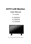
CCTV LCD Monitor
User Manual
For modes:
EL-97MA1RE
_____________________
Contents
1. Introduction………...........................................................................................................................................1
2. Work Safety Information................................................................................................................................ 2
2.1. Product Safety Precautions information.......................................................................................................2
2.2. Safety Guidelines.........................................................................................................................................3
2.3. Important Notice Concerning Power Cord Selection...................................................................................3
2.3.1 For the United States and Canada..................................................................................................... 3
2.3.2 For European Countries......................................................................................................................3
2.3.3 For the United Kingdom.......................................................................................................................4
3. Standards and Guidelines.............................................................................................................................5
3.1. FCC Requirements......................................................................................................................................5
3.2. FCC Warning ............................................................................................................................................ 5
3.3 CE Conformity……………........................................................................................................................... 5
3.4 RoHS Compliance Statement.................................................................................................................... 5
3.5 Information on Disposal for Your Old Product..............................................................................................6
4. Hardware Installation.....................................................................................................................................7
4.1 Checking the Accessories Supplied..............................................................................................................7
4.2 VESA bracket installation …………………………………………………………………………………………..7
5. Buttons and Connections...............................................................................................................................7
5.1 Buttons……..................................................................................................................................................7
5.2 Connections..................................................................................................................................................8
6. ID Remote Controller …………………………………………………………………………………………..…….9
7. OSD Setup ………………………………………………………………………………………………………..……10
8. Troubleshooting Guide…………………………………………………………………………………………….…17
9. Applicable Video Timing for PC- analog Video…………………………………………………………….….…18
10.Technical Data ………………………………………………………………………………………………………..19
1
Introduction
Thank you for purchasing the professional CCTV LCD Monitor and welcome to a fantastic new
technology that will completely change the way you look at monitors. The following sections describe
just a few of the major advantages of this LCD monitor. You’ll discover more of its wonderful features
as you use it.
Please note that this manual is used with many similar monitor models. Please check the model
number on the carton and on the back of the unit to make sure if the user manual is applicable to your
machine.
1. The LCD monitor is used in the same way as the CRT monitor. There is no need to change the
hardware of your computer, just plug it in and it is ready for use.
2. The monitor will accept and display analog video (NTSC or PAL) , PC-type video and Digital video
sources .
3. Low radiation and reduced flickering compared to traditional CRT monitors that minimizes eyestrain
and health hazards.
4. The compact size makes transportation easier and allows to use in many applications.
5. This LCD monitor can support PC-VGA, Composite , S-Video signals.
6. The composite video input ports accept different signal sources, e.g. Camera, DVR .. etc.
7. The design allows VESA wall mounting installation.
8 This monitor includes special functions for 3D comb filter, De-interlace, Anti burn-in mode, auto
impedance switch for looping video connection .
9. The remote controller has 9999 ID code to control individual monitor on the wall. (Remote controller
is an optional device)
1
2
Work Safety Information
Caution and Warning
CAUTION !!
RISK OF ELECTRIC SHOCK
DO NOT OPEN
CAUTION: To reduce the risk of electric shock, do not
remove cover (or back).
No internal parts can be serviced by users.
Refer servicing to qualified personnel.
TO PREVENT FIRE OR SHOCK HAZARD, DO NOT EXPOSE THIS CCTV
LCD MONITOR TO RAIN OR MOISTURE.
WARNING
2.1
“HIGH VOLTAGE EXISTS ON THE BACK LIGHT POWER LEAD OF THIS
CCTV LCD MONITOR. BEFORE SERVICING, DETERMINE THE
PRESENCE OF HIGH VOLTAGE BY CONNECTING THE H.V. METER
BETWEEN THE BACK LIGHT POWER LEAD AND CHASSIS ONLY“
Product Safety Precautions
Follow all warnings and instructions marked on the product.
1.
Do not use this product near water.
2.
This LCD monitor should be installed on a stable horizontal base.
3.
When cleaning, use only a neutral detergent cleaner with a soft damp cloth. Do not spray with liquid or
aerosol cleaners.
4.
Do not expose this LCD monitor to direct sunlight or heat. Hot air may cause damage to the cabinet
and other parts.
5.
Adequate ventilation must be maintained to ensure reliable and continued operation and to protect the
LCD monitor from overheating. Do not block ventilation slots and openings with objects or install the
LCD monitor in a place where ventilation may be obstructed.
6.
Do not install this LCD monitor near a motor or transformer where strong magnetism is generated.
Images on the LCD monitor will be distorted and the color irregular.
7.
Do not allow metal pieces or objects of any kind fall into the LCD monitor through ventilation holes.
8.
Do not attempt to service this unit yourself. Removal of the LCD monitor cover may expose you to
dangerous voltage or other hazards. Refer all servicing to qualified service personnel.
9.
Unplug this product from the wall outlet and refer servicing to qualified service personnel in the event
that:
- Liquid is spilled onto the product or the product is exposed to rain or water.
- The product does not operate normally when the operating instructions are followed.
- The product has been dropped or the cabinet has been damaged.
- The product exhibits a distinct change in performance, indicating a need for service.
- The power cord or plug is frayed or damaged.
- Has referred to Troubleshooting Tips and problems still can’t be solved.
2
2.2
Safety Guidelines
English
This device must be operated with the original power supply.
CAUTION
The socket outlet should be installed near the equipment and should be
easily accessible.
Français
WARNING
CAUTION
Switzerland…….SEV
Canada……CSA
Britain…………..BASE/BS
Germany…..DE
Japan…………...Electric Appliance Control Act.
Español
2.3
USA………..UL
Important Notice Concerning Power Cord Selection
The female receptacle of the cord set must meet IEC-60320 requirements and may look like this (Figure A1
below):
Polski
2.3.1
Figure A2
For the United States and Canada
Maximum Current Rating of Unit
18 AWG
16 AWG
14 AWG
10 Amps
12 Amps
12 Amps
SVT
18 AWG
17 AWG
10 Amps
12 Amps
Svenska
For European Countries
In Europe you must use a cord set which is appropriate for the receptacles in your country. The cord set is
HAR-Certified, and a special mark that will appear on the outer sheath, or on the insulation of one of the inner
conductors.
3
Nederlands
2.3.2
Size of Conductors in Cord
SJT
Česky
In the United States and Canada the male plug is a NEMA5-15 style (Figure A2, above), UL Listed, and CSA
Labeled. For units which are mounted on a desk or table, SVT or SJT type cord sets may be used. For units
which sit on the floor, only SJT type cord sets may be used. The cord set must be selected according to the
current rating for your unit. Please consult the table below for the selection criteria for power cords used in
the United States and Canada.
Code Type
Italiano
The power cord set for this unit has been enclosed and has been selected according to the country of
destination. It must be used to prevent electric shock. Use the following guidelines if it is necessary to replace
the original cord set, or if the cord set is not enclosed.
Figure A1
Deutsch
Use a power cord that is properly grounded. Always use the appropriate AC
power cord that is certified for the individual country. Some examples are
listed below:
2.3.3
For the United Kingdom
For your safety please read the following text carefully.
If the fitted molded plug is unsuitable for the socket outlet, then the plug should be cut off and disposed of
safely.
DANGER
Do not plug the cut-off plug into a socket outlet! There is a danger of severe
electrical shock!
If a new plug is to be fitted, please observe the wiring code as shown below. In case of doubt, please consult
a qualified electrician.
WARNING
This appliance must be earthed (grounded).
IMPORTANT
The wires in this mains lead are colored in accordance with the following codes:
z Green-and-Yellow : Ground (Earth)
z Blue : Neutral
z Brown : Live
If the colored wires of the mains lead of this appliance do not correspond with the colored markings
identifying the terminals in your plug, proceed as follows:
The wire which is colored GREEN-AND-YELLOW must be connected to the terminal in the plug which is
marked by the letter E or by the Earth symbol or colored GREEN or GREEN-AND-YELLOW.
The wire which is colored BLUE must be connected to the terminal in the plug which is marked with the letter
N or colored BLACK.
The wire which is colored BROWN must be connected to the terminal in the plug which is marked with the
letter L or colored RED.
If you have any questions concerning the proper power cord to use, please consult the dealer from whom you
purchased the product.
4
Standards and Guidelines
3.1
English
3
FCC Requirements
z Increasing the separation between the equipment and the receiver.
z Connecting the equipment into an outlet on a circuit different from the one which the receiver is connected.
Español
z Reorienting or relocating the receiving antenna.
Deutsch
The equipment has been tested and found to comply with the requirements stipulated in Part 15 of FCC
regulations for a Class B digital device. These requirements are designed to provide reasonable protection
against harmful interference in a residential installation. This equipment generates, uses and can radiate
radio frequency energy and, if not installed and used in strict compliance with the instructions, may disrupt
radio communications. However, there is no guarantee that interference will not occur in a particular
installation. If this equipment does cause detrimental interference with radio or television reception, which can
be determined by turning the equipment off and on, the user is encouraged to try to correct the interference
by taking one or more of the following measures:
Français
This device complies with Part 15 of the FCC Rules and Regulations. Operation is subject to the following
two conditions: (1) This device may not cause harmful interference, and (2) this device must tolerate any
interference encountered, including interference that may cause improper operation.
z Consulting the dealer or an experienced radio/TV technician for help.
Changes or modifications not expressly approved by the manufacturer could void the user’s right to operate
the equipment.
Italiano
Shielded interconnected cables and shielded power cords must be used with this equipment to ensure
compliance with the pertinent RFD emission limits governing this device.
Notice of Compliance with Canadian Interference-causing Equipment Regulations
3.2
Polski
This Class B digital apparatus meets all requirements of the Canadian Interference-Causing Equipment
Regulations.
FCC Warning
Svenska
3.3
Česky
To ensure continued FCC compliance, the user must use a grounded power supply cord and the shielded
video interface cord with bonded ferrite cores provided. If a BNC cable is going to be used, use only a
shielded BNC (5) cable. Also, any unauthorized changes or modifications not expressly approved by the
party responsible for compliance could void the user’s authority to operate this device.
CE Conformity
Nederlands
The device complies with the requirements of the directive
2004/108/EC with regard to “Electromagnetic compatibility”
5
3.4
RoHS Compliance Statement
Information on Disposal for Your Old Product
Deutsch
Français
Used electrical and electronic equipment must be treated separately and in accordance with
legislation that requires proper treatment, recovery and recycling of used electrical and
electronic equipment. When this corssed-out wheeled bin symbol is attached to a product, it
means the product is covered by the European Directive 2002/979/EC. If you wish to discard
of this product, please contact your local authorities and ask the correct method of disposal.
The coorect disposal of your old product will help prevent potenital negative consequences
for the environment and human health.
Attention: if you want to dispose of this equipment, please do not use this ordinary dust bin!
Français
English
3.5
English
This display defined in this user manual is 100% RoHS complaint and meets all the requirements set forth in
European Union Directive 2002/95/EC, Restriction of the Use of Certain Hazardous Substances in Electrical
and Electronic Equipment.
Español
Deutsch
Italiano
Español
Polski
Italiano
Česky
Polski Svenska
Česky Nederland
Svenska
s
Nederlands
6
4.
Hardware
This chapter will guide you through the correct installation procedures for the LCD monitor.
4.1. Checking the Accessories Supplied
z LCD monitor body + Desk Stand x 1 pc
z AC power cord x 1 pc
z Adaptor x 1 pc
z D-Sub 15-pin cable (1.8 Meter) x 1 pc
z Ø 3.5mm audio line (1.5 Meter) x 1 pc
z User manual (CD) x 1 pc
z Remote controller x 1 pc (Optional)
z Battery (AAA) x 2 pc (Optional)
4.2 VESA bracket installation
If you want to install the LCD Monitor on the wall , please purchase the bracket that meet the VESA
standard (100x 100 mm). Please install the bracket on the VESA hole that reserved on the back of
cabinet, then install to the wall.
5. Buttons and Connections
5.1 Buttons
1
○
2
○
3
○
4
○
5
○
1 “Source/Exit”
○
1. To select the input signal source when the OSD menu is Off. The available signal source will be shown
in the following order: PC,AV1,S-Video1 .
2. To exit the menu when you finish the setting.
2 “▼/-” Down/Decrease:
○
To move the cursor downwards or to switch over the setting items or to decrease the figure of the setting
selected.
3 " Power :
○
Press button to turn the power on and press again to turn the power off.
7
f ”▲/+” Up/Increase :
To move the cursor upwards or to switch over the setting items or to increase the figure of the setting
selected.
g“Menu/Enter” :
To Enter the OSD menu or confirm the setting.
5.2 Connections
2
1
DC12V
Item
3
4
5
RCA
RCA
PC Audio VGA
Audio-R Audio-L
Connector
6
S-Video
7
8
BNC-In BNC-Out
Function
1
○
DC 12 Input
Please use DC 12V, 5A Power Adaptor
2
○
Stereo RCA Audio Input
(R/L)
Stereo audio input , “R“ is right channel (Red) of audio connector,
“L“ is the left channel(White) of the audio of connector.
4
○
PC Audio Input (Ø 3.5mm)
Connect to the audio output of your computer
5
○
D-Sub (VGA) Input
Connect to the VGA output of your computer or DVR
6
○
S-Video Input
Connect the S-Video(4-pin DIN) connector from the DVR or AV
equipment to the Monitor .
7
○
Composite Video Input and
Output (BNC type)
This Video input and output are used for CVBS input and output. This
monitor also supports the“ auto looping“ function, permitting the
connection of another monitor from the output connector.
3
○
8
○
8
6. ID Remote Controller (Optional)
(The ID function is only applicable for some specific models )
c. POWER switch.
Press to turn ON or turn OFF the LCD Monitor.
d. VIDEO SIGNAL Selection:
Press the “AV1” ,“AV2”, “S-VIDEO”, “D-SUB”, “HDMI” button
to enter the selected video source or press the “SOURCE”
button to have the cycle video selection. (PS. AV2 and HDMI
buttons are only applicable for specific models with AV2 and
HDMI connector).
e. PIP Hot Key:
Press PIP button to enter “PIP” setup .
f. PBP Hot Key:
Press PBP button to enter the PBP setup
g. SWAP Hot Key:
Press SWAP button to exchange the main and sub screen.
h. VOL:
Press “+” to increase volume and press “-“ to decrease volume.
i. DEFAULT :
Press “Default” to clear all the setting and return to factory default.
j. MUTE and PAUSE :
Press “MUTE” to mute the sound and press “PAUSE” to pause
the video.
k. OSD setup:
a. Press the “MENU” to enter the OSD menu and press “▲ UP”
or “▼ DOWN” to select setting item and press “ ” RIGHT” to
increase or “ ”LEFT” to decrease the “blue bar” to adjust the
setting.
b. Press the “EXIT” to exit the menu and confirm the setting.
c. Press the “ENTER” to confirm the ID number setting.
l. ID and Number Key:
Step 1: Setup the Monitor ID No.
Press “MENU“ to enter the OSD menu and press “ /+
“ button to select the “Function“ menu and press “▼ DOWN” to
choose “ID “ setup.
To press 4 digit (0001~9999) as the monitor ID No. and press
“ENTER” to confirm the input. When you press the “ID” button,
the screen will show “ ID : 0001 (when you input ” 0001”)
.
9
Step 2: Control the monitor with ID No.
Press “ID“ button, the screen will dispaly the“ ID NO.“, input 4
same digit on “ ID “ and press “ENTER“ to confrim the input. Then
you can control the monitor.
For example:
When you setup the Monitor “ID NO“ is “0001“, you press the
“ID“ button and input 0001 and press “ENTER“ to confirm the
input. You can control the monitor with ID No.0001 only. You are
not able to control other monitors unless you setup all monitors ID
No. is “0001“ or the“ ID „ setup function is on “Off“ status.
Notice !!!
Please don’t setup the 4 digit No. as “0000“ , If you setup the
Monitor ID No. as “0000“ , the ID function will be on “Off“ status.
7.
OSD Setup
Picture (Video Mode)
1. Press the “Menu” key on the buttons to call out the
OSD Menu . Press “▲/+” or “▼/-“ to select
“Picture” mode and press “Menu” key again to select
the “Picture” option.
2. Various picture settings are available from the “Picture”
menu. Use“▲/+” or “▼/-“ to select item that you want
to adjust and press “Menu” key again until grey bar
changes to blue color and press “▲/+” or “▼/-“
increase or decrease the figure that you wish . Press
“Exit” key to return to menu and confirm the setting.
Press two times of “Exit” to exit all the menu.
Brightness
Press“▲/+” or “▼/-“ to increase/decrease the “Blue bar” to adjust brightness. Adjusting brightness to enhance
the level of dark area in the video picture such as night scenes and shadow scenes. Increasing brightness
will make dark areas more visible.
Contrast
Press “▲/+” or “▼/-“ to increase/decrease the “Blue bar” to adjust contrast. Increasing contrast will make
white area of the video picture brighter. Contrast works in conjunction with “Brightness”.
Backlight
Press “▲/+” or “▼/-“ to increase/decrease the “Blue bar” to adjust backlight. Increasing the figure will enhance
the backlight. Decreasing the figure will reduce backlight.
Sharpness
Press “▲/+” or “▼/-“ to increase/decrease the “Blue bar” to adjust sharpness. Using sharpness to adjust the
detail enhancement to the video picture. Increasing the figure will enhance the edges of objects in the video
picture. Decreasing the figure will reduce enhancement.
10
Tint
Press “▲/+” or “▼/-“ to increase/decrease the “Blue bar” to adjust hue. Using hue to adjust the color of flesh
tones. Increasing figure will make the picture with more red in appearance. Decreasing figure will shift the
picture with more green in appearance.
Saturation
Press “▲/+” or “▼/-“ to increase/decrease the “Blue bar” to adjust color saturation. Increasing color figure will
make the color more intense. Reducing color figure will make the color less intense.
Color Temp.
Select the Color Temp.” for white balance. Press “Menu” to enter “OK” mode. There are six settings to
choose from (1)Standard (2). Cold (3).Warm (4) User. To select “User” you may press “▲/+” or “▼/-“ to
increase/decrease the “Blue bar” to adjust color of Red, Green and Blue.
Sound (Video Mode)
1. Press the “Menu” key on the buttons to call out the OSD
“Menu” . Press “▲/+” or “▼/-“ to select “Sound” option
and press “Menu” key again to select the “Sound” mode.
There are 2 sound modes to choose from (1) Standard
(2) User.
2. To select “User” you may press “▲/+” or “▼/-“ to
select item that you want to adjust
Bass
Press “▲/+” or “▼/-“ to increase/decrease the “Blue bar” to enhance the bass or reduce the bass.
Treble
Press “▲/+” or “▼/-“ to increase/decrease the “Blue bar” to increase the treble or reduce the treble.
Balance
Press “▲/+” or “▼/-“ to increase/decrease the “Blue bar” to enhance right speaker or enhance the left
speaker. Put the figure on “0” will keep the balance of right speaker and left speaker.
Speaker Enhance
Press “▲/+” or “▼/-“ to switch On or switch Off the speaker enhancement.
Volmue
Just press “▲/+” or “▼/-“ to increase/decrease the “Blue bar” to adjust volume when “OSD” Menu is Off mode.
PIP (Video Mode)
Press the “Menu” key on the buttons to call out the OSD
“Menu” . Press “▲/+” or “▼/-“ to select “PIP” mode
and press “Menu” key again to select the “PIP” option.
11
Sub Source
Press the “Menu” key to enter the Sub Source and press “▲/+” or “▼/-“ to select PC as the sub-screen .
Sub Size
Press the “Menu” key to enter the Sub Size and press “▲/+” or “▼/-“ to select the size of sub-screen . There
are 4 size to select (1).Small (2).Medium (3).Large (4) PBP or select Off to close PIP setting.
Swat
Press “▲/+” or “▼/-“ key to enter the Swat and press “Enter” to activate “OK” and swat the main screen and
sub-screen.
Sub Position
Press the “Menu” key to enter the Sub Position and press “▲/+” or “▼/-“ to select 0~4 as the position of subscreen 0 : Top left 1: Bottom left 2: Central 3: Top right 4: Bottom right
Display (Video Mode)
Press the “Menu” key on the buttons to call out the OSD
“Menu” . Press “▲/+” or “▼/-“ to select “Display” mode
and press “Menu” key again to select the “Display” option.
H-Position
Use to change horizontal position of the picture. You may press “▲/+” or “▼/-“ key to select “H-Position” and
press “▲/+” key to increase “Blue bar” to shift the picture to right or press “▼/-“ to decrease “Blue bar” to shift
the picture to left.
V-Position
Use to change vertical position of the picture. You may press “▲/+” or “▼/-“ key to select “V-Position” and
press “▲/+” key to increase “Blue bar” to shift the picture up or press “▼/-“ to decrease “Blue bar” to shift the
picture down.
Image Ratio (Video mode)
In order to meet different applications in video output, there are 5 image ratio to choose (1) 4:3 Full (2) 16:9
Full (3). 4:3 Over-1 (4). 16:9 Over-1 (5). 4:3 Over-2. Press “▲/+” or “▼/-“ key to select the format ratio you
want.
1. 4:3 Full
The 9.7” panel is 4:3 format, this mode will make the image fully fills up the screen on both “Vertical” and
“ Horizontal” lines when you connect to DVR and Camera.
2. 16:9 Full
This mode just zoom out the 4:3 Full format to provide a 16:9 format to display 16:9 signal .
3. 4:3 Over-1
The format is over scan mode to make the image fill up the screen and cut about 2% on “Vertical” and
2% on “Horizontal” lines..
4. 16:9 Over-1
This mode just zoom out the 4:3 Over-1 format to provide a 16:9 format to display 16:9 signal .
12
5. 4:3 Over-2
The format is over scan mode to make the image fill up the screen and cut about 4% on “Vertical” and
4% on “Horizontal” lines
Image Optimize
Select the “ Image Optimize” for best image setting. Press “Menu” to enter “OK” mode. To select DNR
(Dynamic Noise Reduction), the DNR will reduce the noise level and improve the video quality. There are
four levels to select (1) Low (2) Medium (3) High (4) Off. Press “▲/+” or “▼/-“ key to select the level.
Function (Video Mode)
Press the “Menu” key on the buttons to call out the OSD
“Menu” . Press “▲/+” or “▼/-“ to select “Function” mode
and press “Menu” key again to select the “Function” option.
Language
The default language is English, you may press the “Enter” key and press “▲/+” or “▼/-“ key to select
language you want. There are 6 languages to select (1) English (2) French (3) Germany (4) Spanish (5)
Italian (6).Chinese
OSD Time
If you want the OSD Menu to stay longer on the screen, you may press “▲/+” or “▼/-“ key to select “OSD
Time” and press “Enter” key to adjust the time , it can be adjusted from 5 second to 60 second.
OSD Blend
If you want to change the background color of OSD Menu, you may press “▲/+” or “▼/-“ key to select
“ Background color” . Press “Enter” key and press “▲/+” or “▼/-“ key to increase/decrease the “Blue bar”, the
color will change from light blue to dark blue.
Sleep Time
The function will make the monitor in sleep mode to save the power when monitor is in standby mode. To
press “Enter” to enter the option and press “▲/+” or “▼/-“ key again to select (1). 10 Min (2). 20 Min. (3).30 Min
(4). 60 Min (5).90 Min (6).120 Min (7).150 (8).180 (9) Off. To select 10 Min that means the monitor will enter
sleep mode when monitor is in standby mode for more than 10 Min. The other time options are the same rule.
Anti Burn-in
The function can prevent the LCD panel from burn-in when camera or DVR is always displaying the same
picture source at all times. Press “▲/+” or “▼/-“ key to select “ Anti Burn-in” and press “Enter” to enter the
option and press “▲/+” or “▼/-“ key again to select (1). 30 Min (2). 60 Min. (3).90 Min (4).120 Min (5).150 Min
(6).Off. To select 30 Min. the image will move left for one pixel for every 30 minutes, to select 60 Min, the
image will move left for one pixel for every 60 minutes, the other options are the same regulation.
ID
The ID function is only applicable for some specific models, if the model you brought has the ID function,
Please check the ID setup procedure on page 9.
13
Default
If you want to back to factory default, press “▲/+” or “▼/-“ key to select “ Default” “ and press “Enter” key to
activate “OK”
Exit
Press the “Menu” key and press “▲/+” or “▼/-“ to select
“Exit” to exit the OSD menu.
Picture (PC/VGA Mode)
1. Press the “Menu” key on the buttons to call out the
OSD“Menu” . Press “▲/+” or “▼/-“ to select
“Picture” Mode and press “Menu” key again to select
the “Picture” option.
2. Various picture settings are available from the “Picture”
menu. Use“▲/+” or “▼/-“ to select item that you want
to adjust and press “Menu” key again until grey bar
changes to blue color and press “▲/+” or “▼/-“
increase or decrease the figure that you wish . Press
“Exit” key to return to menu and confirm the setting.
Press two times of “Exit” to exit the menu.
Brightness
Press“▲/+” or “▼/-“ to increase/decrease the “Blue bar” to adjust brightness. Adjusting brightness to enhance
the level of dark area in the video picture such as night scenes and shadow scenes. Increasing brightness
will make dark areas more visible.
Contrast
Press “▲/+” or “▼/-“ to increase/decrease the “Blue bar” to adjust contrast. Increasing contrast will make
white area of the video picture brighter. Contrast works in conjunction with “Brightness”.
Backlight
Press “▲/+” or “▼/-“ to increase/decrease the “Blue bar” to adjust backlight. Increasing the figure will enhance
the backlight. Decreasing the figure will reduce backlight.
Color Temp.
Select the Color Temp.” for white balance. Press “Menu” to enter “OK” mode. There are 4 settings to choose
from (1)Standard (2). Cold (3).Warm (4) User. To select “User” you may press “▲/+” or “▼/-“ to
increase/decrease the “Blue bar” to adjust color of Red, Green and Blue.
14
Sound (PC/VGA Mode)
The setup is the same as page No.11 for sound setup
of “Video Mode”.
PIP (PC/VGA Mode)
The setup is the same as page No. 11 for PIP setup
of “Video Mode”.
Display (PC/VGA Mode)
Press the “Menu” key on the buttons to call out the
OSD “Menu” . Press “▲/+” or “▼/-“ to select
“Display” mode and press “Menu” key again to
Select the “Display” option.
H-Position
Use to change horizontal position of the picture. You may press “▲/+” or “▼/-“ key to select “H-Position” and
press “▲/+” key to increase “Blue bar” to shift the picture to right or press “▼/-“ to decrease “Blue bar” to shift
the picture to left.
V-Position
Use to change vertical position of the picture. You may press “▲/+” or “▼/-“ key to select “V-Position” and
press “▲/+” key to increase “Blue bar” to shift the picture up or press “▼/-“ to decrease “Blue bar” to shift the
picture down.
Image Ratio(PC/VGA Mode)
In order to meet different applications in video output, there are 2 image ratio to choose (1) 4:3 (2) 16:9
Press “▲/+” or “▼/-“ key to select the ratio you want.
1. 4:3
9.7” panel is 4:3 format, this mode to make the image fully fills up the screen on both “Vertical” and
“ Horizontal” lines.
2. 16:9
This mode to make the format as 16:9 to support the 16:9 signal input from PC.
15
Image Optimize
Select the “ Image Optimize” for best image setting. Press “Menu” to enter “OK” mode. To select the Auto
Color,
The monitor will auto fine-tune the color as default.
Phase
Use phase to fine-tune the monitor to perfectly ADC clock phase synchronize to the video signal source
under RGB mode. Press “▲/+” or “▼/-“ to increase/decrease the “Blue bar” to adjust the Phase.
Clock
Use Clock to fine-tune the monitor when phase value is wrong. Press “▲/+” or “▼/-“ to increase/decrease the
“Blue bar” to adjust the Clock..
Auto Adjust
Use “Auto Adjust” to fine-tune the display to perfectly synchronize to the video signal source under RGB
mode. Press “Menu” to enter “OK” mode to activate the Auto Adjust function.
Function (PC/VGA Mode)
The setup is the same as page 12 for Function
adjustment of “Video Mode”.
Exit
.
Press the “Menu” key and press “▲/+” or “▼/-“
to select “Exit” to exit the OSD menu.
16
8. Troubleshooting Guide
When you experience issues with the CCTV LCD Monitor , before contacting your retailer where you
made your purchase, please check the following items. The most common issue is with the
connection of AV equipment or graphic card. We recommend that at the same time of troubleshooting,
also refer to the AV equipment or graphic card user manual. Please do not use a higher refresh rate
than the maximum specified by the CCTV LCD Monitor.
Issue
No image appears on the
LCD Monitor screen
Abnormal image
Abnormal image colors on
the screen
Interference appearing on the
screen
Can only hear audio, but no
image on the screen
Can only see video, but no
audio
Troubleshooting
Check if the computer or AV equipment power cord is securely connected
to the wall socket, or to the extension cord.
Check if the LCD Monitor power switch is at the “on” position and the LED
on the front of LCD Monitor is in still green.
Check if the computer or AV equipment video (signal) cables are properly
secured.
Check and make sure the computer or AV equipment video (signal) cables
are properly and securely connected to the sockets on back of the LCD
Monitor.
Check and make sure the LCD Monitor video (signal) cables are properly
and securely connected to the D-Sub, BNC, RCA sockets on back of the
computer.
Please refer to Chapter “Function” to check if there is any improper
adjustment or setting.
Please make sure both video inputs are properly connected (BNC /RCA/
/S-Video and D-Sub).
Please make sure both audio inputs are properly connected, the audio
input plugs are RCA and Ø 3.5mm audio line-in.
Check if the volume is at the lowest level.
17
9.
Applicable Video Timing for PC- analog Video
The following table list are the better display quality modes for analogy signal (PC) supported by this
LCD monitor. The LCD monitor will stop working or has poor picture quality when other modes out of
below list input.
D-sub Mode timing :
Note : 1360 x 768 for D-sub mode only
18
10. Technical Data
Model
System
Panel Size
Resolution
Pixel Pitch (H xV)
Contrast Ratio
Luminance
Aspect Ratio
Response Time
Video Signal
Video Color System
Scan Frequency
EL-97MA1RE
9.7" LCD (LED Backlight)
1024 x 768
0.192(H) x 0.1924(V)
600:1
200 cd/㎡
4:3
Tr+Tf=35 ms
Analog RGB Signal ,
composite signal 1.0Vpp/75 ohm, Y:1Vp-p, C:0.3Vp-p
NTSC/PAL auto detection switch
H:31K~81KHz, V:56~75Hz
Operation Interfaces
Front Panel Controls
OSD Control
OSD Language
Menu/Enter, Power,+/- ,Source/Exit
Yes
English, Francais, Deutsch, Espanol, Italiano,Russian,Chinese(7)
Input / Output Connector
Input Connector
Output Connector
D-sub(VGA)
S-Video
Video Input(BNC Jack)
RCA Audio (R+L)
PC Audio Input (Ø3.5 Jack)
Power Input (DC 12V, 5A)
Video Output(BNC) x 1
x1
x1
x1
x 1 sets
x1
x1
Mechanical & Electrical Design
PIP & PBP
Video Output Looping
3D Comb Filter
De-Interlace
Power Failure Auto Recovery
Anti Burn-in
Digital Noise Reduction
Pro 5 Image Ratio
VESA Mounting
Front Bezel Material
Back Cabinet Material
Stand Material
Speaker Output
Power Input
Power Consumption
Working Temperature
Working Humidity
Unit Dimension(WxHxD)
Packing Dimension(WxHxD)
Net Weight
Gross Weight
Regulatory
Color
Yes
Yes
Yes
Yes
Yes
Yes
Yes
Yes
100 x 100 mm
Metal
Metal
Metal
2W x 2
DC12V, 5A
15W(Max)
5~+40 ℃
20% ~ 85%RH
259 x 221 x 89 mm
390 x 403 x 178 mm
1.88Kg
3.7Kg
CE,FCC,RoHS
Black
Accessory
Power Cable
Power Adaptor
D-Sub (VGA) Cable
3.5mm audio Cable
User Manual (CD)
1
1
1
1
1
19