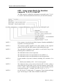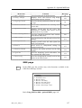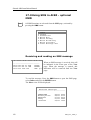
1
INSTRUCTION MANUAL SIMRAD AI80 Automatic Identification System Part no: A101-19 English Simrad AI80 Instruction Manual Note! Kongsberg Seatex AS makes every effort to ensure that the information contained within this document is correct. However, our equipment is continuously being improved and updated, so we cannot assume liability for any errors which may occur. Warning! The equipment to which this manual applies must only be used for the purpose for which it was designed. Improper use or maintenance may cause damage to the equipment or injury to personnel. The user must be familiar with the contents of the appropriate manuals before attempting to operate or work on the equipment. Kongsberg Seatex AS disclaims any responsibility for damage or injury caused by improper installation, use or maintenance of the equipment. Copyright © 2007 Kongsberg Seatex AS The information contained within this document remains the sole property of Kongsberg Seatex AS. No part of this document may be copied or reproduced in any form or by any means, and the information contained within is not to be communicated to a third party, without the prior written consent of Kongsberg Seatex AS. ii Man_instr_AI80_r1 Instruction manual Document revisions Rev Date Written by Checked by Approved by 0 1 07.11.06 26.04.07 ISt ISt PCB PCB PCB PCB Document history Rev. 0 First edition. In this manual the previous AI80 User's Manual, rev. 2, and the AI80 Installation Manual, rev. 2, are combined into one manual. In addition the following new information is included or altered in the AI 80 Instruction Manual: Inland Waterway functionality included, Added Inland Data, Network, Clear Messages, Port Activity, SWR and Monitoring command descriptions. System menu pages changed, updated type approval certificate, WEEE information included, MKD cable specifications added. Rev. 1 Info on RTCM output inserted. . To assist us in making improvements to this manual, we would welcome comments and constructive criticism. Please send all such - in writing to: Kongsberg Seatex AS Pirsenteret N-7462 Trondheim, Norway or by e-mail to: [email protected] Man_instr_AI80_r1 iii Simrad AI80 Instruction Manual About this manual This manual is intended as a reference guide for installing, operating and maintaining the Simrad AI80 Automatic Identification System. In this manual, references to buttons on the control unit are written in boldface, and in a different text style (e.g. VIEW button, SHIFT button, ENTER button). Important text that requires special attention from the reader is emphasized as follows: Note! Used to draw the reader's attention to a comment or some important information. Caution! Used to warn the reader that a risk of damage to the equipment exists if care is not exercised. WARNING! Used when it is necessary to warn personnel that a risk of injury or death exists if care is not exercised. FCC part 15 statement This equipment has been tested and found to comply with the limits for a Class A digital device, pursuant to Part 15 of the FCC Rules. These limits are designed to provide reasonable protection against harmful interference when the equipment is operated in a marine and/or commercial environment. This equipment generates, uses and can radiate radio frequency energy and, if not installed and used in accordance with the instruction manual, may cause harmful interference to radio communications. The equipment is not inteded for operation in a residential area. Operation in such an area is likely to cause harmful interference in which case the user will be required to correct the interference at his own expense. Additional information to the user Changes or modifications not expressly approved by Kongsberg Seatex AS will void the user's authority to operate the equipment. iv Man_instr_AI80_r1 Instruction manual This manual is divided in the following sections: 1. System overview An overview of the AI80 system and its components. 2. Technical specifications Specifications for the system and for all separate units in the AI80 system. 3. Installation Reference guide for correct installation of the AI80 system. 4. Connecting and configuring external equipment Describes how external equipment is connected to the AI80 system. 5. User interface An overview of the AI80 user interface, display pages and menus and the Minimum Keyboard and Display (MKD) unit. 6. Configuration Initial software parameters that have to be entered before the system is ready to use. 7. Operation Main operating procedures for using the AI80 system. 8. Maintenance Describes repair and servicing procedures. 9. Troubleshooting Troubleshooting procedures that could be performed for checking hardware and external interface. 10. Appendix A - Vessel identifiers An overview of all vessel identifiers that should be used in an AIS system. 11. Appendix B - IEC 61162-1, IEC/PAS 6162 100 sentence description Initial software parameters that have to be entered before the system is ready to use when using the optional MKD. 12. Appendix C - Spare part list List of standard and optionally supplied components. 13. Appendix D - Type approval certificate Copy of type approval certificate included. Man_instr_AI80_r1 v Simrad AI80 Instruction Manual 14. Appendix E - Declaration of conformity Copy of Declaration of Conformity included. 15. Appendix F - AIS troubleshooting form Troubleshooting forms to be filled in and sent to Customer Support if experiencing problems with AI80 system. 16. Appendix G - Optional VHF antenna Technical specifications for Comrod AV7 antenna. 17. Appendix H - Optional MKD General description of optional MKD and operating procedures when using it. 18. Appendix I - Configuration using optional MKD Initial software parameters that have to be entered before the system is ready to use when using the optional MKD. vi Man_instr_AI80_r1 Instruction manual Abbreviations and acronyms ABK ABM ACA AIS AIS 1 Addressed and Binary Broadcast Acknowledgement Addressed Binary and Safety Related Message AIS Regional Channel Assignment Universal Ship-borne Automatic Identification System 161.975 MHz (87B – 2087) AIS 2 162.025 MHz (88B – 2088) ALR Alarm ARPA Automatic Radar Plotting Aid ASCII American Standard Code for Information Interchange ATN Aids to Navigation BIIT Built In Integrity Tests BS Base Station BW Bandswidth COG Course Over Ground DGPS Differential GPS DGNSS Differential Global Navigation Satellite System DSC Digital Selective Calling DTE Data Terminal Equipment ECDIS Electronic Chart Display and Information System ECS Electronic Chart System EMC Electromagnetic Compatibility EPFD Electronic Position Fix Device EPFS Electronic Position Fix System ERI Electronic Reporting International ETA Estimated Time of Arrival FATDMA Fixed Allocation TDMA FTP File Transfer Protocol GNSS Global Navigation Satellite System GPS Global Positioning System HDG Heading IALA International Association of Lighthouse Authorities ICMP Internet Control Message Protocol IEC International Electrotechnical Commission IMO International Maritime Organisation Man_instr_AI80_r1 vii Simrad AI80 Instruction Manual IP Internet Protocol ITU International Telecommunication Union IWW Inland WaterWay LAN Local Area Network LAT Latitude LED Light Emitting Diode LON Longitude LR Long Range MKD Minimum Keyboard Display MMSI Maritime Mobile Service Identity MSG Message N/A Not Applicable NMEA National Marine Electronics Association OOW Officer on Watch PI Presentation Interface PPS Pulse-per-second PUR Polyurethane PWR Power ROT Rate of Turn RTCM Radio Technical Commission of Maritime Service RX Receive SMS Short Message Service SOG Speed Over Ground SOLAS International Convention for Safety of Life at Sea SOTDMA Self Organising TDMA SR Safety Related SWR Standing Wave Ratio TBD To Be Defined TCP Transmission Control Protocol TX Transmit TXT Text Message UDP User Datagram Protocol UTC Universal Co-ordinated Time UTP Unshielded Twisted Pair VDL VHF Data Link viii Man_instr_AI80_r1 Instruction manual VDM VHF Data Link Message VDO VHF Data Link Own Vessel Message VHF Very High Frequency VTS Vessel Traffic Service WEEE Waste Electrical and Electronic Equipment Man_instr_AI80_r1 ix Simrad AI80 Instruction Manual Contents 1 SYSTEM OVERVIEW..........................................................................................1 1.1 General............................................................................................................1 Coverage .........................................................................................................2 AIS information content .................................................................................2 1.2 2 System components ........................................................................................3 TECHNICAL SPECIFICATIONS.......................................................................7 2.1 Health, environment and safety ......................................................................7 2.2 Restrictions in guarantee ................................................................................7 2.3 Power ..............................................................................................................8 2.4 Data input .......................................................................................................8 2.5 Specifications..................................................................................................8 AI80 Mobile Unit ...........................................................................................8 AI80 Minimum Keyboard Display (MKD)..................................................11 MKD cable specifications ............................................................................13 Mounting bracket for AI80 - dimensions .....................................................16 GPS antenna (GPS4) ....................................................................................18 Pilot plug.......................................................................................................19 3 INSTALLATION .................................................................................................21 3.1 General..........................................................................................................21 3.2 Unpacking and handling ...............................................................................21 3.3 Installation procedure ...................................................................................21 3.4 Cabling..........................................................................................................23 3.5 Location of the units .....................................................................................24 Antenna location...........................................................................................24 3.6 MKD unit......................................................................................................25 Mechanical installation.................................................................................25 3.7 AI80 Mobile Unit .........................................................................................26 Mechanical installation.................................................................................26 Cable connection ..........................................................................................26 Rear connections...........................................................................................27 x Man_instr_AI80_r1 Instruction manual Data signals...................................................................................................27 3.8 Pilot plug.......................................................................................................28 3.9 External alarm...............................................................................................28 3.10 GPS antenna .................................................................................................29 Mechanical installation.................................................................................29 GPS antenna offset arms...............................................................................30 Checking the antenna cable ..........................................................................30 Sealing antenna connectors ..........................................................................30 3.11 VHF antenna.................................................................................................31 4 CONNECTING AND CONFIGURING EXTERNAL EQUIPMENT ..........33 4.1 General..........................................................................................................33 4.2 Presentation interface ...................................................................................34 Physical location...........................................................................................34 Port configuration .........................................................................................34 Input sentences .............................................................................................34 Proprietary input sentences...........................................................................35 Output sentences...........................................................................................35 4.3 Long-Range interface ...................................................................................36 Physical location...........................................................................................36 Port configuration .........................................................................................36 Input sentences .............................................................................................36 Output sentences...........................................................................................36 4.4 Sensor input ..................................................................................................37 Physical location...........................................................................................37 Port configuration .........................................................................................37 Input sentences .............................................................................................37 Priority of Position........................................................................................38 Priority of SOG and COG.............................................................................38 Priority of Heading .......................................................................................38 Priority of Rate of Turn ................................................................................38 4.5 5 RTCM output................................................................................................39 USER INTERFACE.............................................................................................41 Man_instr_AI80_r1 xi Simrad AI80 Instruction Manual 5.1 AI80 user interface .......................................................................................41 Display..........................................................................................................41 Keypad..........................................................................................................41 LED indicators..............................................................................................41 5.2 Buttons..........................................................................................................42 5.3 Using display and keypad.............................................................................44 Manoeuvring and selecting...........................................................................44 Dialogue boxes .............................................................................................44 Editing ..........................................................................................................45 Information ...................................................................................................46 5.4 AI80 display pages and submenus................................................................46 Ship list view ................................................................................................48 Main menu ....................................................................................................49 Alarms and LR..............................................................................................49 Dynamic data ................................................................................................50 Settings .........................................................................................................51 SMS ..............................................................................................................53 Downperiods.................................................................................................55 Channel Management ...................................................................................56 System...........................................................................................................57 Diagnostics ...................................................................................................59 Pin code protection .......................................................................................61 6 CONFIGURATION.............................................................................................63 6.1 General..........................................................................................................63 6.2 Security settings AI80 ..................................................................................63 6.3 Entering static data .......................................................................................64 6.4 Network settings ...........................................................................................65 6.5 Configuring external serial ports ..................................................................65 6.6 VHF data link ...............................................................................................65 6.7 Configuring radio channels ..........................................................................66 Viewing a region's settings ...........................................................................66 Adding a region ............................................................................................66 xii Man_instr_AI80_r1 Instruction manual Edit current region ........................................................................................67 6.8 Configuration through PI_serial/ PI_LAN ...................................................67 6.9 Configuration through setup file...................................................................68 Network parameters......................................................................................68 6.10 Message types...............................................................................................69 6.11 Inland Waterway...........................................................................................72 Setup file.......................................................................................................72 Dynamic data ................................................................................................76 Inland data ....................................................................................................76 Inland Waterway Area data ..........................................................................76 Inland Waterway Static Ship data ................................................................77 Inland Waterway Voyage Ship data .............................................................77 Ship data parameters.....................................................................................78 7 OPERATION........................................................................................................79 7.1 General..........................................................................................................79 7.2 Turning the AI80 system ON .......................................................................80 7.3 Restarting the AI80 system...........................................................................80 7.4 Adjusting brightness and contrast.................................................................80 AI80 display settings ....................................................................................80 7.5 Changing parameters during operation.........................................................81 Setting the Navigational Status.....................................................................81 Entering Voyage Data ..................................................................................81 7.6 Turning the VHF transmitter OFF................................................................81 7.7 Using the AI80 message system ...................................................................82 Using SMS in AI80 ......................................................................................82 New SMS received .......................................................................................82 The Inbox......................................................................................................82 Write Message ..............................................................................................82 The Outbox ...................................................................................................83 Viewing and editing predefined messages ...................................................83 How to write a predefined message..............................................................83 7.8 The alarm system..........................................................................................84 Man_instr_AI80_r1 xiii Simrad AI80 Instruction Manual AI80 alarms ..................................................................................................84 Displaying and acknowledging alarms.........................................................84 7.9 Long-Range messages (option) ....................................................................85 AI80 long-range............................................................................................85 Deleting a long-range request.......................................................................85 8 MAINTENANCE .................................................................................................87 8.1 General..........................................................................................................87 8.2 Periodic maintenance....................................................................................87 MKD Units ...................................................................................................87 Mobile Unit...................................................................................................87 8.3 Repair and modifications..............................................................................88 Exchanging antenna cables...........................................................................88 Exchanging GPS or VHF antennas ..............................................................88 8.4 Software updates...........................................................................................89 Manual update ..............................................................................................89 Update using FTP .........................................................................................89 9 TROUBLESHOOTING ......................................................................................91 9.1 General..........................................................................................................91 9.2 Hardware problems.......................................................................................91 Power supply failure .....................................................................................92 GPS and VHF antenna cable connections ....................................................92 GPS and VHF antenna malfunction .............................................................92 GPS receiver failure......................................................................................92 VHF transceiver failure ................................................................................93 9.3 External data interface problems ..................................................................93 Data input from main GPS/GNSS source.....................................................93 Heading from vessel heading sensor ............................................................94 AIS unit restarts ............................................................................................94 10 APPENDIX A - VESSEL IDENTIFIERS..........................................................95 11 APPENDIX B - DIGITAL INTERFACE IEC 61162-1....................................99 Hardware ......................................................................................................99 Proprietary 61162-1 sentences....................................................................100 xiv Man_instr_AI80_r1 Instruction manual New IEC 61162-1 sentences.......................................................................103 IEC 61162-1, Ed. 2, sentences....................................................................123 12 APPENDIX C - SPARE PART LIST...............................................................135 13 APPENDIX D - TYPE APPROVAL CERTIFICATE ...................................137 14 APPENDIX E - DECLARATION OF CONFORMITY ................................141 15 APPENDIX F - TROUBLESHOOTING FORM............................................143 16 APPENDIX G - OPTIONAL VHF ANTENNA ..............................................147 17 APPENDIX H - OPTIONAL MKD UNIT.......................................................149 17.1 Optional MKD unit - general information..................................................149 Display........................................................................................................149 Rotating knob .............................................................................................149 Display page buttons ..................................................................................149 Input buttons ...............................................................................................150 17.2 Optional MKD - technical specification.....................................................150 17.3 Optional MKD - installation.......................................................................151 Mechanical installation...............................................................................151 The optional MKD cable ............................................................................152 17.4 Optional MKD - display pages and submenus ...........................................153 Displaying submenus..................................................................................154 Entering Data ..............................................................................................154 View page ...................................................................................................155 Menu page ..................................................................................................156 SMS page....................................................................................................157 Alarm page..................................................................................................158 17.5 Optional MKD display settings ..................................................................158 17.6 Setting the navigational status ....................................................................159 17.7 Entering voyage data ..................................................................................160 17.8 Turning the VHF transmitter OFF..............................................................161 17.9 Using SMS in AI80 - optional MKD..........................................................162 Receiving and reading an SMS message ....................................................162 Writing and sending SMS messages ..........................................................163 Man_instr_AI80_r1 xv Simrad AI80 Instruction Manual 17.10 The Outbox .................................................................................................167 Removing messages....................................................................................168 17.11 Optional MKD alarms ................................................................................169 Displaying and acknowledging alarms.......................................................169 17.12 Optional MKD long-range..........................................................................170 Resolving a long-range request ..................................................................170 Deleting a long-range request.....................................................................171 17.13 Restarting the AI80 system using optional MKD ......................................172 18 APPENDIX I - CONFIGURATION USING OPTIONAL MKD..................173 18.1 Security settings optional MKD .................................................................173 Setting the security codes ...........................................................................173 Changing the security levels.......................................................................174 18.2 Entering static data optional MKD.............................................................176 18.3 Configuration external serial ports optional MKD.....................................177 18.4 Port settings and MAC address optional MKD ..........................................178 18.5 Answer mode optional MKD......................................................................179 18.6 Configuring radio channels optional MKD ................................................180 Adding a region ..........................................................................................181 Editing current region.................................................................................182 Viewing a region's settings .........................................................................182 xvi Man_instr_AI80_r1 System overview 1 SYSTEM OVERVIEW 1.1 General The Simrad AI80 Automatic Identification System (AIS) uses VHF communication to transmit and receive AIS data. An AIS system operates primarily on two dedicated VHF channels, AIS 1 – 161.975 MHz and AIS 2 – 162.025 MHz. Where these channels are not available regionally, the AIS can be set to other designated channels. The system broadcasts the vessel's position, speed and course over ground as well as static and voyage related information. Short safety related text messages can be sent between vessels or broadcast from shore based AIS stations or Aids to Navigation like buoys and lighthouses. The on-board installed system is designed to operate automatically and as a stand-alone unit. In addition to transmission of AIS data, the system can continuously receive position information from other vessels or shore based stations. GPS SATELLITES BASE STATIONS OPERATOR STATION Man_instr_AI80_r1 1 Simrad AI80 Instruction Manual Coverage The system radio coverage range is similar to other VHF applications and is dependent on the height of the antenna. The propagation differs from that of a radar, due to the longer wavelength, so it is possible to "see" around bends and behind islands if the landmasses are not too high. A typical value to be expected at sea is 20 nautical miles. AIS information content AIS type of information is exchanged automatically between vessels, vessels and shore based stations and vessels and Aids to Navigation like buoys and lighthouses. The information transmitted by a vessel's AIS system is grouped in four categories: Static data MMSI (Maritime Mobile Service Identity) number Call sign and name IMO number Length and beam Location of position fixing antennas on the ship Voyage related data Ship's draught Hazardous cargo type Destination and ETA (at Master's discretion) Type of ship Dynamic data Position with accuracy indication and integrity status Time in UTC COG (Course over ground) SOG (Speed over ground) Heading Navigational status Rate of turn Safety-related messages Reading and writing short safety related messages 2 Man_instr_AI80_r1 System overview Data reporting and transmission rates AIS data as stated above are autonomously sent at different update rates and thus reporting rates are dependent on the ship's navigational mode. Dynamic information is dependent on speed and course alteration while static and voyage related data are transmitted every 6 minutes or on request. Thus fast ferries will report their navigational data at a higher update rate than ships at anchor. Ship's Manoeuvring Condition Nominal Reporting Interval Ship at anchor 3 min. Ship 0 to 14 knots 10 sec. Ship 0 to 14 knots and changing course 3 1/3 sec. Ship 14 to 23 knots 6 sec. Ship 14 to 23 knots and changing course 2 sec. Ship > 23 knots 2 sec. Ship > 23 knots and changing course 2 sec. 1.2 System components An AI80 system includes the following units: • AI80 Class A Mobile Unit • GPS Antenna (GPS4) • AI80 Minimum Keyboard and Display, 21-button with Pilot Port Man_instr_AI80_r1 3 Simrad Simrad AI80 Instruction Manual GPS antenna (A101-01) Simrad AI80 MKD (A101-12_1) Mounting kit GPS antenna (A101-02) Interconnection cable (A101-03) Adapter cable (A100-93) Interface cable to MKD (A101-13_1) Class A Mobile Station (A101-11_1) The Mobile Unit broadcasts the vessel's position, speed and course as well as static and voyage related information. The unit incorporates two VHF receivers, one VHF transmitter, one DSC receiver, one GPS receiver and a processor. The internal GPS receiver is used for time synchronisation and for back-up position sensor. The MKD unit provides a simple user interface to the Mobile Unit with basic presentation of configuration data and position data in a 4x20 character display. Buttons are used for selecting display pages, for input of data to the system, and for writing text messages transmitted to other vessels or shore based AIS stations. 4 Man_instr_AI80_r1 System overview A Pilot Plug is included in the AI80 system and is located at the rear of the MKD. The plug enables the pilot to connect a Personal Pilot Unit (PPU) to the AIS system. The supplied L1 GPS antenna is delivered with a universal antenna mounting kit and an adapter cable with N connectors for connection to a customer supplied GPS antenna cable, e.g. RG-214. Note ! Man_instr_AI80_r1 A customer supplied VHF antenna must be included in the AI80 system. A qualified antenna must cover marine band (156 MHz - 164 MHz), have omni-directional vertical polarization and provide 2 to 5 dB gain. 5 Simrad AI80 Instruction Manual THIS PAGE INTENTIALLY LEFT BLANK 6 Man_instr_AI80_r1 Technical specifications 2 TECHNICAL SPECIFICATIONS 2.1 Health, environment and safety Operation or troubleshooting of Simrad AI80 equipment will not imply any risk for high voltages, explosions or exposure to gas. The AI80 is compliant with IEC 60950/EN60950 standards regarding product safety (low voltage) and IEC 60945/EN60945 standards on electromagnetic compatibility (immunity/radiation), vibration and climatic conditions. All AIS electrical and electronic components have to be disposed separately from the municipal waste stream via designated collection facilities appointed by the government or local authorities. The correct disposal and separate collection of your old appliance will help preventing potential negative consequences for the environment and human health. It is a precondition for reuse and recycling of used electrical and electronic equipment. For more detailed information about disposal of your old appliance, please contact your local authorities or waste disposal service. Until further notice is given regarding reuse, disassembly or disposal, the equipment at end-of-life, could be returned to Kongsberg Seatex AS if there is no local WEEE collection. The equipment is marked with the following pictogram. 2.2 Restrictions in guarantee The liability of the manufacturer is limited to repair of the AI80 only, and excludes consequential damages such as customer's loss of profit or damage to other systems traceable back to AI80 malfunction. The warranty does not cover malfunctions of the AI80 resulting from the following conditions: a) The customer has opened the Mobile Unit b) Over-voltage or incorrect power connection Man_instr_AI80_r1 7 Simrad AI80 Instruction Manual 2.3 Power Voltage input:................................24 V DC (nominal) range 18 – 35 V Power consumption:....................50 W peak, approx. 30 W continuous 2.4 Data input Gyro compass:................................................. NMEA 0183 version 3.0 GPS Main source: ........................................... NMEA 0183 version 3.0 DGPS corrections:......................................RTCM – SC104 version 2.1 2.5 Specifications AI80 Mobile Unit Dimensions:........................................................................ Refer page 9 Weight: ..........................................................................................3.4 kg Colour:........................................................................................... Black Enclosure material:...............................................Varnished aluminium Environmental protection:............................................................... IP40 Temperature range: Operating:................................... –15 to +55°C (+5° to +131°F) Storage: ..................................... –25 to +60°C (-13° to +140°F) Humidity - operating:............................................................ 0-95% RH Vibration test: Displacement:.................................. 1 mm from 2 Hz to 13 Hz Acceleration: ............................... 7 m/s2 from 13 Hz to 100 Hz Compass safe distance..................................................................0.35 m VHF radio: Number of transmitters: ............................................................1 Number of receivers:.................................................................3 Channel spacing: .................................................12.5 or 25 kHz Frequency range:................................................ 156 - 165 MHz Transmitter power: ............ 2 W or 12.5 W nominal (selectable) AIS 1 (Channel 87B):........................................... 161.975 MHz AIS 2 (Channel 88B):........................................... 162.025 MHz DSC receiver: ....................................................... 156.525 MHz 8 Man_instr_AI80_r1 Technical specifications GPS receiver: Type: ...................................................................μBlox TIM LF Operating frequency (reception only): .................................. 1575.42 MHz ± 10 MHz TOP VIEW FRONT VIEW REAR VIEW SIDE VIEW EXPLODED Man_instr_AI80_r1 9 Simrad AI80 Instruction Manual BOTTOM VIEW - EXPLODED ISO VIEW 10 Man_instr_AI80_r1 Technical specifications AI80 Minimum Keyboard Display (MKD) Dimensions:............................................................................ See below Weight: ..........................................................................................0.4 kg Colour:........................................................................................... Black Cable length (to Mobile Unit):..........................................................7 m Enclosure material:....................................................................... Plastic Environmental protection:..........................IP56 (when panel-mounted) Temperature range: Operating:.....................................–15 to +55°C (+5 to +131°F) Storage: ...................................... –25 to +70°C (–13 to +158°F) Humidity - operating:............................................................ 0-95% RH SIMRAD 2 ABC 3 5 JKL 6 MNO 7 PQRS 8 TUV 9 WXYZ VIEW 0 1 109 mm 4 AIS CANCEL OK GHI INFO OFF EDIT DEF SHIFT DEL 217 mm FRONT VIEW 96 mm 206 mm Pilot plug Main unit REAR VIEW Man_instr_AI80_r1 11 Simrad AI80 Instruction Manual 50 mm 12 SIDE VIEW 5 2. Ш 95 96 12 201 206 DRILLING & CUTOUT DIMENSION OF AI80 DISPLAY (MM) A full-scale drawing of the display is supplied with the documentation package. 12 Man_instr_AI80_r1 Man_instr_AI80_r1 CPC 17-28 series 2 AMP 205840-3 AMP/receptable (square Flanged) 206486-1 ribbon cable connector, 10p J1 Male J2 Male J3 Female K1 K2 Type J1 Pilot_RD(B) Pilot_RD(A) Pilot_TD(B) Pilot_TD(A) Pilot_C TX RX MKD_GND MKD_VDD Nr Gender 1 2 3 4 5 6 7 8 9 10 36.018 Cable specification inside external MKD Descr. 1 2 3 4 5 6 7 8 9 10 1 2 3 4 5 6 7 8 9 TX RX MKD_GND MKD_VDD J3 J2 Pilot_TD(A) Pilot_TD(B) Pilot_RD(A) Pilot_RD(B) Pilot_C Signal name Pilot_RD(B) Pilot_RD(A) Pilot_TD(B) Pilot_TD(A) Pilot_C J2 6 5 4 1 9 J1 Signal name J3 6 TX 6 7 RX 7 8 no connection 8 9 MKD_GND 9 10 MKD_VDD 10 J1 1 2 3 4 5 Kongsberg Seatex AS To AIS To Pilot interface KE 7/9-04 To EMKD PCB(P1) Assembly note: Cable J1-J2, ca 10cm Cable J1-J3, 10 conductor Install Connectors J1 and J2 on EMKD casing prior to assembly of cable ribbon cable, ca 20cm K2 K1 Technical specifications MKD cable specifications 13 14 Type Nr K3 Miltronic 066654 J4 AMP-206039-1 J5 AMP-205839-3 Pilot_RD(B) Pilot_RD(A) Pilot_TD(B) Pilot_TD(A) Pilot_C AIS_RX AIS_TX Shield MKD_GND MKD_VDD 1 2 3 4 5 6 7 8 9 10 J4 From AIS From EMKD UNITRONIC LiHCH (TP) 6 x 2 x 0.25mm2 twisted pair, braided screen, halogen free, 7.0 meter Descr. K3 1 2 3 4 5 6 7 8 9 10 J5 Pilot_RD(B) Pilot_RD(A) Pilot_TD(B) Pilot_TD(A) Pilot_C EMKD_TX EMKD_RX MKD_GND MKD_VDD A101-13_7(_15) Cable specification AI 80 - External MKD KE 7/9-04 Kongsberg Seatex AS Pair #5 Pair #4 Pair #3, one conductor used Pair #2 Pair #1 Simrad AI80 Instruction Manual Man_instr_AI80_r1 Man_instr_AI80_r1 Gender Female Female Nr J6 J7 K4 1 2 3 4 5 6 7 8 9 10 J6 Pilot_RD(B) Pilot_RD(A) Pilot_TD(B) Pilot_TD(A) Shield RX TX Shield MKD_GND MKD_VDD ribbon cable connector, 10p AMP-206038-1 Type K4 1 2 3 4 5 6 7 8 9 10 Descr. J7 Pilot_RD(B) Pilot_RD(A) Pilot_TD(B) Pilot_TD(A) Shield RX TX Shield MKD_GND MKD_VDD To AIS-PCB (P409) To EMKD 10 conductor ribbon cable, ca 30cm 36.032 Cable specification inside AI80 (P409) KE 7/9-04 Kongsberg Seatex AS Technical specifications 15 Simrad AI80 Instruction Manual Mounting bracket for AI80 - dimensions Side view 16 Man_instr_AI80_r1 Technical specifications 16.58 5.15 6.50 96 135o Right bracket Man_instr_AI80_r1 Left bracket 17 Simrad AI80 Instruction Manual GPS antenna (GPS4) Dimensions:.............................................................. Refer figure below Weight: ......................................................................................0.130 kg Cable adapter set (2 cables): ....................................................2 x 0.5 m Voltage input:.................................5 V DC from the AI80 Mobile Unit Temperature range: ............................... -35°C - +70°C (-31° - +158°F) Humidity: .........................................................................100% (sealed) Mounting:......................................................1"14 thread (standard US) 38 193 211 313 34 120 18 Man_instr_AI80_r1 Technical specifications Pilot plug AMP CPC series 2/Receptable (Square Flanged) Shell size 11, 9-pin. The pilot plug is located at the rear of the MKD. Man_instr_AI80_r1 19 Simrad AI80 Instruction Manual THIS PAGE INTENTIALLY LEFT BLANK 20 Man_instr_AI80_r1 Installation 3 INSTALLATION 3.1 General To reduce the installation cost, crew members (Crew) qualified to perform electrical installations can perform part of the installation. However, qualified service personnel (SP) should carry out the final commissioning. 3.2 Unpacking and handling Care should be taken when unpacking and handling the equipment. A visual inspection should be made to ensure that the equipment has not been damaged during shipment, and that all parts are present. A standard AI80 delivery includes: • AI80 Mobile Unit • AI80 MKD • GPS4 GPS antenna including mounting kit and cable adapter set • Documentation, including Instruction Manual 3.3 Installation procedure The table on the following pages describes a recommended installation procedure. It also describes items that could be performed by the vessel crew and items that must be carried out by qualified personnel. The table also includes page references to the various items' installation description in this manual. Man_instr_AI80_r1 21 Simrad AI80 Installation Manual Description Performed by Crew 1. Mount the GPS4 antenna included in the AI80 system and the third party VHF antenna. x 2. Connect the adapter cable to the GPS4 antenna. x 3. Pull cables from the antennas to the AI80 Mobile Unit. x 4. Check the GPS and VHF cables for short circuit between the centre conductors and shield (ground). x 5. Mount the AI80 Mobile Unit - mount the MKD. x Ref page SP 30 25 onwards 6. Connect the GPS adapter cable to antenna cable. x 7. Connect the GPS4 antenna and the VHF antenna to the plugs on the rear of the Mobile Unit (connectors to be mounted by SP). x 26 8. Connect the MKD unit to the Mobile Unit using the supplied cables. x 26 9. Connect the external main GPS sensor to Sensor port 1, 2 or 3 on the Mobile Unit. x 10. Connect the vessel's main heading sensor to Sensor port 1, 2 or 3 on the Mobile Unit. x 11. Provide other interface from external sensors to the Mobile Unit. x 12. Connect the Power to the Mobile Unit. Make sure the power supply is from the vessel's emergency supply. x 13. Apply power to the AI80 system. x 14. Check that the indication on the LED indicators on the Mobile Unit is as follows: GPS LED: blinks green once each second TX LED: blinks green and amber, at the most 10 seconds between each blink MSG LED: blinks green and amber, at the most 10 seconds between each blink 15. Perform the software setup procedure. 22 x x Man_instr_AI80_r1 Installation 3.4 Cabling Double shielded coaxial cables equal or better than RG-214 are recommended when connecting the GPS and VHF antennas to the AI80 system. Coaxial cables should be installed in separate signal cable channels/tubes and at least 10 cm away from power supply cables. All outdoor installed connectors on the coaxial cables should be fitted with preventive isolation such as shrink-stocking with silicone to protect against water penetration. Avoid sharp bends of the cables. A bend may change the characteristic impedance of the cable. CABLE NO. DESCRIPTION CABLE LENGTH PART NO. 1 Interface cable to MKD/Pilot Plug 7m A101-13_1 2 Adapter cable GPS 0.5 m A100-93 3 Interconnection cable GPS4 0.5 m A101-03 4 Mounting kit, GPS antenna A101-02 The figure below shows cables and cable length in a standard AI80 system. 4 3 1 2 Note ! Man_instr_AI80_r1 Shaded items and cables are not part of a standard AI80 scope of supply. 23 Simrad AI80 Installation Manual Antenna cables The antenna cables should be as short as possible to minimise attenuation of the signal. The cables should be located at least 10 cm away from power supply cables. The table below shows the maximum cable length (VHF) for the different antenna cable types. Cable type Max. length at 160 MHz RG58 10 metres "PUR" 58 * 10 metres RG213 30 metres RG214 * 30 metres LowLoss ½" * 100 metres * Recommended cable types. Power cables Use minimum 2 x 2.5 mm2 cables to avoid voltage drop. 3.5 Location of the units The units included in the AI80 system should be mounted with special regard to the units' environmental protection, temperature range and cable length. Refer Technical specifications, page 7 onwards. Antenna location The AIS equipment, like any other ship borne transceiver operating in the VHF maritime band, may cause interference to a ship's VHF radiotelephone. This interference may occur as a periodic (e.g. every 20 s) soft clicking sound on a ship's radiotelephone. This affect may become more noticeable when the VHF radiotelephone antenna is located near the AIS VHF antenna, and when the radiotelephone is operating on channels near the AIS operating channels (e.g. channels 27, 28 and 86). The figure below shows recommended location and distance between the different antennas. 24 Man_instr_AI80_r1 Installation 3.6 MKD unit Mechanical installation The MKD may be panel or bracket (option) mounted. The optional mounting bracket may be ordered separately. The unit should be mounted with special regard to the operator's need for easy operation. Avoid mounting the MKD where it is easily exposed to sunlight, as this will shorten the lifetime of the display. If this is not possible, make sure the units are always covered with a protective cover when not in use. Panel mounting Make sure that the mounting location includes space for plug and cable bend. The mounting surface must be flat and even to within 0.5 mm. 1. Remove the 4 front panel corners from the MKD. 2. Drill 4 mounting holes and make a panel cut-out according to dimensional drawing, pages 11 and 12. 3. Fasten the MKD to the panel with the supplied 19 mm screws. 4. Apply the front panel corners. Note ! Man_instr_AI80_r1 Do not over-tighten the mounting screws. 25 Simrad AI80 Installation Manual Bracket mounting (option) When the MKD is bracket mounted (item A101-14), it is not weatherproof from the back. When bracket-mounted, the exposed parts of the plugs should be protected against salt corrosion. 1. Locate the cradle on the mounting site and mark the 4 holes for the screws on the mounting surface. 2. Drill the 4 holes and screw the cradle to the mounting surface. 3. Use the supplied screws to fasten the MKD to the left and right brackets. 4. Apply the front panel corners. Use the two locking knobs to assemble the cradle with the left and right brackets and adjust the MKD for the best viewing angle. 3.7 AI80 Mobile Unit Mechanical installation The Mobile Unit should be mounted in a place with proper ventilation. The unit is mounted with four bolts, refer dimensional drawing on page 10. Ensure that there is enough space on the rear side of the unit for installation of plugs and cables. A minimum distance of 220 mm between the unit and the wall is required. Make sure that unit is properly secured to the deck/bulkhead. Clamps are recommended to secure power and data cables connected to the Mobile Unit. Cable connection The rear panel of the Mobile Unit contains connectors for GPS, VHF, external MKD, data signals and power (+24V DC). The connector types are as shown in the table below: Type 9 pins D-Sub, male MKD TNC connector, Female GPS antenna N-connector, Female VHF antenna Screw terminals P1, P2 Screw terminals 26 Connected to: Data I/O Power Man_instr_AI80_r1 Installation Rear connections MKD PILOT GPS VHF EXT MKD P1 POWER + P2 Data signals The figure below shows the location of the AI80 data signals on the P1 (left connector row), P2 (right connector row). Refer to chapter 4 for description of signals. For detailed electrical description, see Appendix B - Digital interface IEC 61162-1. 10 SENS2_TD(B) SENS2_TD(A) SENS2_C SENS1_TD(B) SENS1_TD(A) SENS1_C SENS3 C PI_C SENS2_RD(A) SENS3 TD(A) PI_TD(A) SENS1_RD(A) SENS3 TD(B) PI_TD(B) SENS2_RD(B) SENS3 RD(A) PI_RD(A) SENS1_RD(B) SENS3 RD(B) PI_RD(B) 1 P1 20 11 LR_RD(B) LR_RD(A) LR_TD(B) LR_TD(A) LR_C COM1_RXD COM1_TXD GND ALM NO ALM_C ALM_NC ALM C Not used RTCM_TD(B) RTCM_TD(A) RTCM_C COM2_RXD COM2_TXD GND NC RXA_AUDIO RXB_AUDIO RXC_AUDIO 12 Not used 1 P2 13 24 Note ! RD(A) is low relative to RD(B) when idle. TD(A) is low relative to TD(B) when idle. Note ! All data cables must be twisted pair cables with shield. Man_instr_AI80_r1 27 Simrad AI80 Installation Manual All cables should be terminated to shield using the clamps on the mounting plate. 3.8 Pilot plug A Pilot plug is included in the AI80 system and is located at the rear of the AI80 MKD. The plug is used for connecting a Personal Pilot Unit (PPU) to the AI80 system. The pilot plug is an AMP CPC series 2/Receptacle (Square Flanged), Shell size 11, 9-pin. In case of a panel mounted MKD, an extension cord must be used. Default baud rate is 38400, N, 8, 1. Signal name Seatex notation Pin on AMP 206486-1 TX(A) Pilot_TD(A) (TXA) 1 TX(B) Pilot_TD(B) (TXB) 4 RX(A) Pilot_RD(A) (RXA) 5 RX(B) Pilot_RD(B) (RXB) 6 Shield Shield 9 3.9 External alarm The Mobile Unit does not include an acoustic alarm, but has a built-in alarm functionality. An alarm will open the alarm relay, which can be used to trigger an external alarm. The diagram below shows how an external alarm may be connected to the rear of the Mobile Unit. 28 Man_instr_AI80_r1 Installation AI80 Rear Panel BUZZER ALM_NC + ALM_C NC NO P2 - 11 12 + - + - FROM UPS SUPPLY 3.10 GPS antenna Mechanical installation The GPS antenna included in the AI80 system is used for time synchronisation and computation of backup position fix. In addition to this GPS antenna, the AI80 should be connected to the vessel's main GPS system at the rear of the Mobile Unit. Sensor input 1-3 may be used. Optimum location of the GPS antenna is important to ensure continuous track of all visible GPS satellites. The following should be taken into consideration during installation: − The GPS antenna must be installed where it has a clear view of the sky and thus the objective is to see the horizon freely through 360 degrees with a vertical observation of 5 to 90 degrees above the horizon. − Small diameter obstructions, such as masts and booms, do not seriously degrade signal reception but such objects must not eclipse more than a few degrees of any given bearing. − The antenna should be located at least 3 metres away from and out of the transmitting beam of high power transmitters (S-band radar and/or Inmarsat systems). This includes the ship's own AIS VHF antenna if it is located separately. Refer figure on page 25. Man_instr_AI80_r1 29 Simrad AI80 Installation Manual Use the supplied antenna mounting kit when mounting the antenna. Appropriate crimping tools must be used. GPS antenna offset arms A B C The mounting location for the internal GPS antenna and for the main GPS antenna connected to the AI80 system, needs to be input to the AI80 as a part of the configuration settings. The figure shows the offset arms that have to be configured. Refer Entering static data, pages 64 and 176. D Checking the antenna cable After the mechanical and electrical installation is completed, the coaxial cables should be checked for short circuit between centre conductor and shield (ground) with the antenna disconnected. If not short-circuited, the antenna cable could be connected to the Mobile Unit. Sealing antenna connectors The outdoor antenna connectors have to be sealed with self-bounding tape and PVC/Vinyl tape for waterproofing. Coil the self-bounding tape from one cable end to the other. Use at least two layers of tape. After coiling, make a bounding by pressure of fingers. Coil at least two layers of PVC/Vinyl tape without stretching. After coiling, make a bounding by pressure of fingers. 30 Man_instr_AI80_r1 Installation 3.11 VHF antenna The VHF antenna is not included in a standard AI80 system, but has to be part of the AIS installation. A qualified antenna must cover marine band (156 MHz - 164 MHz), have omni-directional vertical polarization and provide 2 to 5 dB gain. For installation of this antenna, refer to documentation delivered by the antenna supplier. Refer also to the figure on page 25 for location. Verify that there is no short circuit between centre conductors and shield (ground) before the cable is connected to the Mobile Unit. Seal the antenna connectors as described for the GPS antenna. As an option Kongsberg Seatex AS may provide an antenna with part number A100-58, shown in Appendix G - Optional VHF antenna. Man_instr_AI80_r1 31 Simrad AI80 Installation Manual THIS PAGE INTENTIALLY LEFT BLANK 32 Man_instr_AI80_r1 Connecting and configuring external equipment 4 CONNECTING AND CONFIGURING EXTERNAL EQUIPMENT 4.1 General In general, all sensors installed in compliance with other carriage requirements of SOLAS Chapter V should be connected to the AI80 system. Increased navigational performance can be achieved by interfacing the AI80 to an ECDIS, ECS and/or radar. All external equipment is connected to the AI80. For termination, refer Data signals, page 27. VHF-transmitter Heading VHF-receive ch. 70 GNSS VHF-receive ch. AIS 1 VHF-receive ch. AIS 2 Interface board GNSS/DGNSS Antenna VHF switch VHF Antenna GPS receiver MKD unit Note ! Rate of Turn ECDIS Radar AIS Transponder Shielded twisted pair cables shall be used for the high-speed serial data ports. The following sections present the port configuration and IEC 611621 sentences that may be used when connecting external equipment to the AI80 system. Detailed description of the IEC 61162-1 sentences are found in Appendix B - Digital interface IEC 61162-1, page 99. For terminal location, refer to the figure on page 27. Man_instr_AI80_r1 33 Simrad AI80 Installation Manual 4.2 Presentation interface The presentation interface consists of two physical ports: PI and Pilot port. Both ports are functionally equivalent. The PI port provides a primary port for connecting onboard equipment such as ECDIS, radar, Long Range AIS etc. The Pilot port is used for the Pilot Plug included in the AI80 system. This plug is intended for the ship's pilot equipment, service equipment, etc. Physical location Installed on P1, pins 11 - 15. See figure on page 27. Port configuration The PI and Pilot port have the following default settings: Baud Rate Parity Bits Stop Bit 38400 N 8 1 The baud rate is configurable to either 38400 or 57600. This due to the amount of data. Refer to Configuring external serial ports, pages 65 and 177. Input sentences 34 Sentence Content VSD Voyage static data SSD Ship static data ABM Addressed binary message BBM Broadcast binary message AIR AIS interrogation message ACA AIS channel assignment command ACK Acknowledgement message LRF Long range acknowledge Man_instr_AI80_r1 Connecting and configuring external equipment Proprietary input sentences Sentence Content MMSI MMSI number IMO IMO number PORT Serial port configuration parameters Output sentences Man_instr_AI80_r1 Sentence Content Transmission interval ABK Acknowledgement message Upon reception of messages 7 and 13, and when sending message 15 VDO VHF Data link own message 1 Hz nominal ALR Alarm messages 30 seconds/1 min. TXT Indication messages When change of status ACA AIS channel assignment command When change of status VDM VHF Data link message When receiving on VDL LRI Long-range interrogation When LR request received & when LR response sent LRF Long-range function identification When LR request received & when LR response sent LR1 Long-range response When LR response sent LR2 Long-range response When LR response sent LR3 Long-range response When LR response sent 35 Simrad AI80 Installation Manual 4.3 Long-Range interface The Long Range interface provides a two-way interface for equipment that provides for long-range communications, such as Inmarsat. Physical location Installed on P2, pins 1 - 5, see figure on page 27. Port configuration The Long Range port has the following default settings: Baud Rate Parity Bits Stop Bit 4800 N 8 1 The baud rate is configurable from 1200 to 57600. Refer to Configuring external serial ports, pages 65 and 177. Input sentences Sentence Content LRI Long-range interrogation LRF Long-range function identification Output sentences 36 Sentence Content Transmission interval LRF Long-range function identification When LR response sent LR1 Long-range response When LR response sent LR2 Long-range response When LR response sent LR3 Long-range response When LR response sent Man_instr_AI80_r1 Connecting and configuring external equipment 4.4 Sensor input Physical location Sensor1 is installed on P1, pins 16 - 20, Sensor2 is installed on P1, pins 6 - 10 and Sensor3 is installed on P1, pins 1 - 15, see figure on page 27. These ports are mainly intended to serve as inputs from ships' primary navigation systems such as position sensor data and heading sensor data (the ports are configurable and transmission of two-way data is possible). Port configuration The sensor inputs Sensor1, Sensor2 and Sensor3 are equivalent and the default settings are as follows: Baud Rate Parity Bits Stop Bit 4800 N 8 1 The baud rate is configurable from 1200 to 57600. Refer to Configuring external serial ports, pages 65 and 177. Input sentences Sentence Content From version GGA Position, TOD, position quality (diff/non-diff) 1.5 → GNS Position, TOD, position quality (diff/non-diff) 3.0 → GLL Position, TOD, position quality (diff/non-diff) 2.0 → DTM Datum 3.0 → VBW SOG, COG (derived from speed components) 3.0 → VTG SOG, COG 1.5 → RMC Position, TOD, position quality (diff/non-diff), SOG, COG 1.5 → HDT Heading 1.5 → GBS RAIM indicator 3.0 → ZDA TOD and Date 1.5 → OSD Position, TOD, SOG, COG, Heading 2.0 → ROT Rate of turn 2.0 → Man_instr_AI80_r1 37 Simrad AI80 Installation Manual If the sensor inputs are configured with redundant data, the tables below describe the priorities of the redundant data. Priority of Position Priority Sentence 1 RMC 2 GNS 3 GGA 4 GLL Priority of SOG and COG Priority Sentence 1 RMC 2 OSD 3 VBW 4 VTG Priority of Heading Priority Sentence 1 OSD 2 HDT Priority of Rate of Turn 38 Priority Sentence 1 ROT 2 OSD (derived from heading) 3 HDT (derived from heading) Man_instr_AI80_r1 Connecting and configuring external equipment 4.5 RTCM output When the AIS unit receives VDL message 17, the RTCM part of this message is output on the RTCM port. Man_instr_AI80_r1 39 Simrad AI80 Installation Manual THIS PAGE INTENTIALLY LEFT BLANK 40 Man_instr_AI80_r1 User interface 5 USER INTERFACE 5.1 AI80 user interface SIMRAD 2 ABC 3 5 JKL 6 MNO 7 PQRS 8 TUV 9 WXYZ VIEW 0 1 4 AIS CANCEL OK GHI INFO OFF EDIT DEF SHIFT DEL Display 4 x 20 character display with LED backlight. Keypad 21-button keypad, alpha numeric and navigation keys. LED indicators The LED indicators on the front of the Mobile Unit can be used to monitor status as well as data reception and transmission. LED TX MSG GPS ALM Man_instr_AI80_r1 Colour Off Amber Green Red Off Amber Green Amber Green Off Red Description Transmitter idle Transmitting on AIS channel B Transmitting on AIS channel A Transmitter turned off No message/report being received Message/report received on channel B Message/report received on channel A Indirect synchronisation free run Internal GPS OK, GPS sync selected No alarm Alarm - alarm relay activated 41 Simrad AI80 Installation Manual 5.2 Buttons Manoeuvring in the display: move the "viewport" up, down, left and right using the ARROW buttons in order to display the text. A display page is not limited to 4x20 characters. The manoeuvring allows the user to move a "viewport" up/down and sideways in order to display the entire text. This "window" of 4x20 characters used for viewing the text, is called a viewport in this manual. - Main Menu -----------Alarms and LR Dynamic Data Settings ▼ SMS Downperiods Chn.Management System Viewport Display page Entering data: by pressing the EDIT button when an editable parameter is selected allows input of text, numbers and symbols. Enter text by pressing the character buttons, enter numbers by first pressing SHIFT followed by the selected number. Press SHIFT again to return to character buttons. Enter SPACE and other non-alphabetic symbols by using the Number 1 button in alpha numeric mode. Selecting: by using the ARROW buttons the user can move the cursor when the correct parameter has been selected. Press OK to view or enter submenus. Buttons are PRESSED to select the relevant functionality and HELD to select alternative functionality when relevant. Some buttons have toggle functionality that is triggered by repeatedly pressing this button. By pressing the buttons below the user can enter text or numbers. Switch between characters and numbers by pressing the SHIFT button. SPACE and non-alphabetic symbols can be entered by using the Number 1 button. When not in Edit mode, the Number 0 button toggles the backlight on/off. 1 4 GHI 7 PQRS 2 ABC 3 5 JKL 6 MNO 8 TUV 9 WXYZ 0 42 DEF OFF Man_instr_AI80_r1 User interface VIEW Press this button to switch between the Main menu, Diagnostics menu and main Ship List view. INFO Press this button to access the help system. SHIFT Press this button to toggle between numeric and alphabetic layout on the keyboard while in Edit mode. DEL When entering text or numbers, pressing this button deletes the characters to the left of the cursor. When entering text or numbers, holding this button deletes all characters to the left of the cursor. EDIT By pressing this button the user can edit the selected parameter. When entering text or numbers, pressing this button cancels the editing. The entered value is discarded. CANCEL When interactive messages or requests are displayed, pressing this button answers the equivalent to No (if applicable), and exits the interactive message screen, returning to the viewport to the previous position and content. Press this button to accept changes or selected parameters. OK When predefined choices are displayed, pressing this button commits the selected choice to the system. When any kind of interactive message or request is displayed, pressing this button answers the equivalent to Yes (if applicable), and exits the interactive message screen, returning the viewport to the previous position and content. Press the buttons below to move the viewport/cursor left, right, up, down (i.e. scroll the lines in the display respectively). Man_instr_AI80_r1 43 Simrad AI80 Installation Manual 5.3 Using display and keypad Manoeuvring and selecting The uppermost line on the viewport is the page title. Select wanted line with the UP/DOWN ARROW buttons. The selected line is marked with an underscore character on the right side of the line content. - Settings ------------Nav.Status Voyage related Gyro calibration ▼ Static data Inland data VHF LR Serial Network PIN The bold lined rectangle illustrates what is shown on the screen. ▲ ▼ symbols indicate that a page has more than three lines of content. Manoeuvre the viewport up and down with the ARROW buttons. ◄ ► symbols indicate that the page contains lines with more than 20 characters. Manoeuvre the viewport left and right with the LEFT and RIGHT ARROW buttons respectively. Select a highlighted item by pressing the OK button. Dialogue boxes Dialogue boxes inform the user about events or state changes that require user interaction. Such events are: • • • • • Alarms SMS Enter PIN Edit error Item Help Dialogue boxes are shown as whole pages, i.e. they are displayed in the whole "viewport", and forces the user to press one or more buttons to continue. The dialogue box indicates the keys required to exit the dialogue box. This is indicated by the button name encapsulated in square brackets. 44 Man_instr_AI80_r1 User interface To facilitate recognition, the uppermost line on a dialogue box is composed of a start pattern of three * signs, and a post fixed pattern of * until the end of the line. A dialogue box prompting for PIN code appears like the figure below. *** PIN Code *********** * [Cancel] [OK] Editing The user can edit a variable by pressing EDIT when highlighted. The value of the current variable is stored and the user can start editing the data. The user selects characters by repeatedly pressing numeric buttons, - Static data ---------MMSI: 000000001 Pos Source: Internal SurveyedLat: 00°00'▼ 2 ABC 1 x - Static data ---------MMSI: 000000002 Pos Source: Internal SurveyedLat: 00°00'▼ or, in cases were there are predefined variables, chooses from a list of these by using the UP or DOWN ARROW buttons. - Serial -------------Sensor 1: 4800 RTCM : 9600 PI : 38400 ▼ 2 1 x ABC - SETTINGS ------------Sensor 1: 4800 RTCM : 4800 PI : 38400 ▼ The button between the displays indicates that pressing this button when in the screen to the left, will result in the changes seen in the screen to the right. After editing, press OK to confirm changes and exit Edit mode, or press CANCEL to discard changes. If the input exceeds the horizontal length of the display (20 chars), it automatically scrolls. When editing is completed and OK is pressed, it scrolls back. Values are saved by holding the OK button pressed. Man_instr_AI80_r1 45 Simrad AI80 Installation Manual Information The Info functionality provides the user with information about the highlighted menu. A dialogue box with help text is provided if such a text is existent for the menu. If not, a default text is displayed. A user help dialogue box may look like this: *** User Help ****** Persons on board, Crew and passengers included [OK] 5.4 AI80 display pages and submenus The table below shows the menu hierarchy. The ARROW buttons, OK and CANCEL buttons are used to navigate in the menu tree. Navigation between Ship List, Main Menu and Diagnostics is done by pressing the VIEW button. This chapter describes all the menu pages in the system. Note ! 46 If optional MKD is connected to the AI80, the menus for optional MKD will also apply to the AI80. Man_instr_AI80_r1 User interface SHIP LIST MAIN MENU Alarms and LR - Active Alarms - LR Requests Dynamic Data Settings SMS - Nav.Status - Voyage Related - Gyro Calibration - Static Data - Inland Data - VHF - LR - Serial - Network - PIN - Inbox - Write Message - Outbox - Predefined - Write Predefined - Clear Messages Downperiods Chn.Management System DIAGNOSTICS Man_instr_AI80_r1 - View Regions - Add Region - Edit Current Region - Version - Status - Control - MAC Address VHF Network Port Activity SWR Levels SWR Test Monitoring Config File 47 Simrad AI80 Installation Manual Ship list view 00.12 RANGE 01.11 02.10 02.22 03.21 06.44 06.55 07.00 023 BRG 025 160 343 299 164 279 234 PRINSESS NAME FOSNINGEN▲ NORDLYS SKIPPER V▼RSE KONG SVERRE BS:25791239 ATN:MUNKHOLMEN SAR:123456789 The default main page of the system is called Ship list view and contains information about nearby vessels. Range, Bearing and Name (MMSI if name not available) are shown. BS: in front of the MMSI indicates an AIS base station. ATN: in front of the ship name indicates an Aids To Navigation target. SAR: in front of an MMSI number indicates a SAR aircraft. Name: VANNINA MMSI: 136547932 CallSign: CA122 LAT: 063°36'31.44N LON: 010º24'13.73E NavStatus: Under way using en Dest: Lia ETA: 2231100 - SHIP DATA ---------------Max.Draught: 5.00 m EPFD: GPS ACC: LOW ▼ RAIM: off Time: 11:54:27 COG: 170.00º SOG: 010.00 kn HDG: N/A ROT: N/A OnBoard: 12 IMO: 123 Type: 2 Keel: 10 LengthA: 12 m LengthB: 2 m LengthC: 12 m LengthD: 2 m DTE: Connected 48 If the operator presses OK for the selected ship, a page displaying all information about that ship appears. The figure shows this page scrolled down. Press CANCEL to return to Ship List View. If the ship name cannot fit in the available space, press OK to view the name in the Ship data page. Horizontal scrolling is not available for the Ship List View. This is a read only page. The line indicator (underscore character) is present none the less to facilitate the Info function if the user presses INFO. Pressing EDIT has no effect on read only pages. Man_instr_AI80_r1 User interface Main menu - MAIN MENU -----------Alarms and LR Dynamic Data Settings ▼ SMS Downperiods Chn.Management System Press VIEW to enter the Main menu. The user can select between Alarms and LR, Dynamic data, Settings, SMS, Downperiods, Chn.Management or System. Select menu with UP and DOWN ARROW buttons and enter the menu with OK. Alarms and LR Alarms and LR involves two different modes: • New Alarm/LR received • List of Alarms and List of LR *** Alarm *********** Tx Malfunction [OK] to ack New alarm When a new alarm is received, a dialogue box will appear. Press OK to acknowledge the alarm. If the alarm condition disappears before it is acknowledged, the dialogue page and the viewport is relocated to the previous page and line. As long as an alarm is active, it can be viewed by navigating to the Active alarms page. - Alarms & LR ------Active alarms LR requests - Active alarms ----Tx malfunction 11:00 VSWR exceeds 10:49 RX Chn1 malf. 10:3▼ RX Chn2 malf. 09:01 Heading Lost 08:33 No ROT info 03:42 Man_instr_AI80_r1 Active alarm All active alarms can be viewed under the Alarms and LR menu by selecting them and pressing OK. Active alarms are listed with the latest alarm on top. This is a read only page. 49 Simrad AI80 Installation Manual *** LR Req 123456789:ABCEFIOPUW [OK] to send [Cancel] to deny 123456789:ab - LR Answers ------111111111: abcef ▲ 222222222: ABCEFIOPUW 333333333: a ▼ 444444444: ce 555555555: abc 666666666: ABCE 777777777: puw New LR When an LR request arrives, a dialogue box prompts the user to send or deny the requested information. The dialogue box provides information about requester's MMSI and the codes for requested information (e.g. C means Position). The Info functionality can describe this upon request. If the user does not respond within the given timeout, the information is denied to the requester. All LR requests are also stored in LR history. Press OK to send the information or CANCEL to reject the information. LR requests LR requests contains history of the last 30 requests. This is also a read only page. The figure shows a list with eight requests. First the MMSI of the requestor followed by the information requested. If the requested information is displayed with small letters, the information is provided, otherwise denied. Dynamic data - Dynamic Data -----Mode: Maritime LAT: 063°36'31.44N LON: 010°24'13.73E COG: 000.00° ▼ SOG: 000.00kn HDG: N/A ROT: N/A EPFD: GPS QUAL: GPS SPS Mode RAIM: On UTC: 02.05.06-08.29 GNSS: Internal Last ChnMgt: N/A 50 The Dynamic Data page shows sensor readings. This is a read only page. Press CANCEL to return to Main Menu. Man_instr_AI80_r1 User interface Settings - Settings ---------Nav.Status Voyage related Gyro calibration Static data ▼ Inland data VHF LR Serial Network PIN From the Main Menu, select Settings, press OK and the Settings page appears. All parameters that can be edited are found here. The INFO button provides the user with additional information about each menu item. In the Settings main menu the user can choose between Nav.Status, Voyage related, Gyro calibration, Static data, Inland data, VHF, LR, Serial, Network or PIN. Editing parameters in these pages is always protected with a PIN-code. To save edited parameters, press the OK button. - Nav.Status -------NavStatus: MOORED Hold [OK] to save - Voyage related ---Dest: Not defined ETA: 24100730 OnBrd: 71 ▼ Draught: Not defined Type: 12 Hold [OK] to save - Gyro interface --Gyro type Calibrate gyro - Gyro type --------Gyro type: GI50 Hold [OK] to save Man_instr_AI80_r1 Nav.Status In this page the user can set the appropriate navigation status. Choose from predefined list. Voyage related All voyage related settings can be viewed and altered in this page. Gyro interface If a stepper or syncro gyro is used for heading input, the heading can be calibrated here. This is done by entering the actual heading. Ensure that the vessel has constant heading when entering correction. Gyro type Here, the type of gyro can be chosen by pressing the EDIT button. The possible gyro types are GI50 and GI51. 51 Simrad AI80 Installation Manual - Gyro calibration -► Corrected heading: 9° Hold [OK] to save - Static data ------Name: VANNINA Call: CA122 MMSI: 136547932 ▼ IMO: 3334445 Keel: 30.5 DimA [m]: 0 DimB [m]: 0 DimC [m]: 0 DimD [m]: 0 LocDimA [m]: 0 LocDimB [m]: 0 LocDimC [m]: 0 LocDimD [m]: 0 Hold [OK] to save - Inland data-------Area Static Voyage ▼ - VHF --------------ChnA: 2087 ChnB: 2088 TxPower: HIGH BW A: Default BW B: Default TX: On VDL: Off Hold [OK] to save - LR ---------------LR Mode: MANUAL Hold [OK] to save 52 Gyro calibration If a stepper or syncro gyro is used for heading input, the heading can be calibrated here. This is done by entering the actual heading. Ensure constant heading when entering correction. Static data All static ship data can be viewed and altered here. If MMSI number is changed, the unit should be restarted, see chapter 7.3. Inland data Description of inland data. See section 6.11, Inland Waterway, for more detailed information. VHF In this page the transmission (TX) can be turned ON/OFF, and also the VDL answer mode can be set. LR In this page the LR mode can be set. Choose between Manual and Automatic. Man_instr_AI80_r1 User interface - Serial -----------Sensor 1: 4800 Sensor 2: 4800 Sensor 3: 4800 ▼ RTCM : 4800 PI : 38400 Pilot : 38400 LR : 4800 - Network ----------IP-addr:15.23.88.77 Subnet: 255.255.255.0 Gateway: 15.23.88.1 Hold [OK] to save - PIN --------------PIN: **** Serial In this page the baud rate for the serial ports can be set. Network In this page the network settings, e.g. IP address, can be altered. PIN In this page the PIN code can be changed. Hold [OK] to save SMS - SMS --------------Inbox Write Message Outbox ▼ Predefined Write Predefined Clear Messages - Inbox ------------122121211 29.Dec 12:39 Rasken 28.Dec 12:39 √ Tuppa 27.Dec 1▼:39 √ Bella 27.Dec 12:39 √ Joey 27.Dec 12:39 √ Elli 27.Dec 12:39 √ Barbie 27.Dec 12:39 Man_instr_AI80_r1 In the SMS main menu the user can choose between Inbox, Write Message, Outbox, Predefined, Write Predefined or Clear Messages. Select with UP/DOWN ARROW buttons and enter page with OK. Inbox Inbox contains received messages (max 30) with the most recent message at the top. 53 Simrad AI80 Installation Manual * Message ********* This message is an inbox message [DEL] to delete ▼ [OK] for next msg [CANCEL] to close [EDIT] to reply - Write message ----Channel: Default Type: Addressed Send to:----------- ▼ Predef.: NONE Message: Hold [OK] to send Channel: Default Type: Addr SR Send to: 257999429 Predef.: NONE Message: This message is sent to the vessel - Write message ----chosen when press ing enter ▲ Hold [OK] to send - Outbox ------------122121211 29.Dec 12:39 √ Rasken 28.Dec 12:39 √ Tuppa 27.Dec 1▼:39 √ Bella 27.Dec 12:39 √ Joey 27.Dec 12:39 √ Elli 27.Dec 12:39 √ Barbie 27.Dec 12:39 - Message -----------This message is an outbox message [DEL] to delete ▼ [OK] for next msg [CANCEL] to close [EDIT] to resend 54 Press UP/DOWN ARROW to select message. OK displays the message to the user. If the message is previously read, a check-sign is shown in front of that line. If the message is more than four lines, UP and DOWN are used to scroll lines. Press DEL to delete the message. Press OK to see next message without deleting. Pressing CANCEL takes the user back to the Inbox without deleting the message. Write message Select Write message in the SMS menu to write a message and the following screen appears. Select channel (A, B, Both, Default), type of message to send (Addressed, Addressed Safety related, Broadcast Safety related) and receiver (from list of available stations). In addition the user can choose a predefined message to appear. When all data are entered, press OK to send message as configured. Outbox Outbox contains all sent messages. If the receiver acknowledged the message, a check-sign is shown in front of that line. The latest message is on top. If the user wants to re-send or read a message, select message with UP/DOWN and press OK. The page shown in the figure is displayed. Selecting EDIT resends the message with the same parameters as last time. Man_instr_AI80_r1 User interface - Predefined --------Happy Day Happy Easter Merry Christmas ▼ Happy New Year Happy Holiday - Write predef. ------Name: Message: Hold [OK] to save - Clear Messages -----Inbox: 10 msgs (2) Outbox: 18 msgs (3) Predefined: empty ▼ Hold [OK] to clear *** NEW SMS *********** 4 unread messages [OK] go to Inbox [CANCEL] later Predefined messages In this page the user can edit, view or delete a previously defined message. Press OK to view or edit a message, press DEL to delete a message. Reading a predefined message has the same functionality as reading a message in Inbox, except that EDIT allows the user to edit the predefined message. Write predefined In the Write predefined page only the required data are available for entry, e.g. the name of the predefined message and the message text. Clear messages In the Clear Messages page the user can delete all messages in the Inbox, Outbox or all the Predefined messages. In addition to the number of messages, the number of unread messages (2) is displayed for the Inbox. For the Outbox, the number of unacknowledged messages (3) is displayed. If the user wants to clear messages, select type of message with UP/DOWN ARROW and hold OK. New SMS received When an SMS is received, the user is notified through a dialogue box that appears on the screen. Press OK to read the message immediately or LEFT ARROW to delete the dialogue box. The message can be found in Inbox. Downperiods - Downperiods ---- ► 23.May 08:00 - 23.May 23.May 09:00 - 23.May 23.May 10:00 - 23.M▼y 23.May 11:00 - 23.May 23.May 12:00 - 23.May Man_instr_AI80_r1 08:30 09:30 10:30 11:30 12:30 This page shows the last ten downtimes (start and stop) for the Base Station on the format DD/MM hh:mm - DD/MM hh:mm. It is a read only page. Press CANCEL to return to Main Menu. 55 Simrad AI80 Installation Manual Channel Management - Chn.Mngt --------View Regions Add Region Edit Current region - Regions ----------REGION 1 REGION 2 REGION 3 ▼ REGION 4 - Region 2 ---------ChnA: 2087 ChnB: 2088 RxTx: TxA/TxB, RxA/Rx▼ TxPower: LOW LAT NE: 64°00'00.00N LON NE: 011°00'00.00E LAT SW: 00°00'00.00N LON SW: 000°00'00.00E BW A: Default BW B: Default Zone: 0 Hold [OK] to save - Add region --------ChnA: 0 ChnB: 0 RxTx: TxA/TxB, RxA/Rx▼ TxPower: LOW LAT NE: 00°00'00.00N LON NE: 000°00'00.00E LAT SW: 00°00'00.00N LON SW: 000°00'00.00E BW A: Default BW B: Default Zone: 0 Hold [OK] to save 56 In the Chn. management menu the user can choose between editing current region, viewing all regions or adding a new region. View regions In this page all regions (max 8) are shown. This is a read only page. Use UP/DOWN ARROW to select the region of interest. The figure shows a list with three regions. Region In this page the selected region is displayed. This page is read only and shows each region's parameters. Add region In this page the user can add a region manually. Refer chapter 6.7. Man_instr_AI80_r1 User interface - Default Values ---ChnA: 0 ChnB: 0 TxPower: HIGH ▼ BW A: Default BW B: Default Hold [OK] to save Edit Current region In this page the user can edit current region settings. Select parameter with UP/DOWN, press EDIT to start editing and OK when finished. Hold OK button to save changes to region. If the user presses CANCEL, he is informed that cancelling will delete his entered region. If the region entered is not a valid region, the user is notified about this through a dialogue box. System - System -----------Version Status Control ▼ MAC Address - Version----------► SW :5.01.01 GPS:uBlox TIM LF FW:5.00 Jan 05 ▼ HW:00000040 - Status ----------► Started: 18.04 13:51 Uptime:13 days 19:01 Restart :0 ▼ POWER_ON_RE Config. :OK - Control ---------Restart Software Upgrade Restart GPS ▼ GPS upgrade VHF upgrade Man_instr_AI80_r1 From the System page the user can see the current Version and Status, Control the unit and see the MAC Address. Version This is a read only page for version information. The software version (SW) and the GPS type and version are shown. Status This is a read only page for information purposes only and it shows the actual status of the unit. Started gives the date and time of the last power-on or restart. Uptime is an informative text indicating the time since the unit was started. Restart tells how many times the unit has restarted since the last power-on restart and the last restart reason. The Config. parameter shows the condition of the setup parameters. Any irregularities will be reported to the watchdog log (WD.LOG) file. Control From the Control page the user can restart the unit, upgrade the software, restart and upgrade the GPS receiver. 57 Simrad AI80 Installation Manual - Restart ---------Restart unit - Software Upgrade Start Upgrade Hold [OK] to start - Software Upgrade ---Backup Successful Please turn off unit and insert new CF card If a system restart is required, select Restart unit in the Restart page and press OK. The unit will now initiate the restarting process. When pressing OK on this page, the configuration data are stored for later retrieval. The unit enters an SW upgrade mode where no other activities are performed until power is cycled. If performing software upgrade, turn off power and insert CF card with new software before power-on of the unit. Upon power-on, the configuration data are automatically retrieved. Thus enabling software upgrade without loss of configuration data. If software upgrade is initiated by accident, simply cycle power to restart the unit. Note! Software Upgrade should only be performed by qualified personnel. - Restart GPS -------Restart GPS - GPS upgrade -------Start upgrade Hold [OK] to start 58 If GPS tracking problems are experienced, restarting the GPS may solve these problems. GPS upgrade info. The GPS receiver software sometimes needs to be upgraded. By pressing OK on this page, the unit enters the GPS software upgrade state, which installs new software. This requires the new software image to be available for the AIS. Man_instr_AI80_r1 User interface - VHF upgrade -------Tx Low: 2 Watt Hold [OK] to upgrade VHF upgrade info. The VHF modules sometimes need to be upgraded. By pressing and holding [OK] on this page, the unit enters the VHF software upgrade state, which installs new firmware. This requires the new firmware image to be available for the AIS on the CF card. Keep in mind that the utility is designed to upgrade all the VHF modules (3 receivers and 1 transmitter) in the AIS unit if the proper firmware files are found on the CF card. When entering the VHF Upgrade page, the current low-power setting for the transmitter is shown on the display. If the low-power output setting for the transmitter should be changed, then edit this entry before issuing the upgrade command. The available options are 1W and 2W. Note that the high power output is always 12W. After the upgrade command is issued, progress and status information is displayed on the screen before the unit automatically restarts itself. - MAC Address -------MSB: 000.005.190 LSB: 000.005.200 In this page the MAC Address is viewed. This is a read only page. Diagnostics - DIAGNOSTICS -------VHF Network Port activity ▼ SWR Levels SWR Test Monitoring Config file - VHF ---------------Tx ChA: MSG01 00:01 Tx ChB: MSG03 00:20 Rx ChA: MSG04 00:03 ▼ Rx ChB: MSG17 00:02 Tx DSC: NONE Rx DSC: NONE Man_instr_AI80_r1 The Diagnostics page shows the submenus available to display, test and debug the communication links and configuration settings. VHF The VHF page displays which messages have been transmitted and received on the VDL interface. This page will automatically be updated every second. 59 Simrad AI80 Installation Manual Network The Network page displays the IP address to which the ICMP ping packets can be transmitted. Pressing OK commits the IP address and relocates the viewport for the Ping page. The Ping page displays statistical results from the ICMP transmissions and receptions. the page will be updated every second. - Network ------------Host: 157.237.86.69 - Network ------------- OK Host: 157.237.86.69 is alive 0% loss Hold [OK] Start ping - Serial -------------PI in : NONE 59:59 PI out : VDO 00:01 LR in : NONE 59:59 ▼ LR out : NONE 59:59 RTCM in : NONE 59:59 RTCM out: NONE 59:59 Sens1 in: NONE 59:59 Sens2 in: NONE 59:59 Sens3 in: NONE 59:59 PLAN in : NONE 59:59 PLAN out: VDO 00:01 ▼ Port Activity The Port Activity page shows the sent and received messages on the Serial (PI), Sensor, LAN (PI) and LR interfaces. The time elapsed since last transmission on each port is also shown (59.59 indicates no activity). SWR Levels The SWR Levels page shows the mean values for SWR for the last 10 transmissions. The SWR, Standing Wave Ratio, for an antenna is a measurement for how much of the transmitted/forwarded power that is reflected back towards the transmitter. - SWR Levels --------Forward :2.03 V(H) Reflected:0.09 V(H) SWR :Low ▼ SWR value:1.1 The Forward and Reflected values are displayed in voltage from the measuring bridge. The "(L)" indicates low power while "(H)" indicates high power. The SWR Level is defined as Low (< 2.0), Medium (>= 2.0 and < 3.0) or High (>= 3.0). The SWR should be Low, i.e. the SWR value should be as low as possible (1.0 is ideal). The page is refreshed every 10 seconds. 60 Man_instr_AI80_r1 User interface SWR Test The SWR Test page is used to carry out an SWR test manually. Holding OK starts the test and 10 measurements are executed within 3 seconds. The AIS message transmission is turned off (TX lamp is red) during the test. The SWR test results are shown when the test is finished. To do a new test, hold OK again. - SWR Test ----------Hold [OK] Start test - Monitoring ----------Monitoring: OFF - Config File -------- ► !*********************** !* !* Seatex AISBS▼ OK - SWR Test results ---Forward :2.03 V(H) Reflected:0.09 V(H) SWR :Low ▼ SWR value:1.1 Hold [OK] New test Monitoring Turns on and off logging of the monitor port. For service purposes only. Config.File Read-out of config. file. For service purposes only. Pin code protection The functionality in the mobile unit is protected by a PIN code. If the user wants to edit a protected variable, e.g. Tx On/Off, he is presented with a dialogue box. The default pin code for AI80 is 1234. *** PIN CODE ******** ** [Cancel] [OK] *** Wrong PIN ******* Use numeric buttons to write PIN code, press OK to confirm. If the PIN code is correct, the user can start editing the variable. If incorrect code is entered, a dialogue box prompting the user to retry, is presented. Press OK to retry or CANCEL to cancel. [OK] to try again [Cancel] to cancel Man_instr_AI80_r1 61 Simrad AI80 Installation Manual THIS PAGE INTENTIALLY LEFT BLANK 62 Man_instr_AI80_r1 Configuration 6 CONFIGURATION 6.1 General The AI80 system is set up with factory settings during testing. The software setup must be performed as a part of the AI80 installation procedure. The software setup is performed from sub-menus available from the Main Menu page, activated by pressing the VIEW button. The respective Main Menu pages are shown below. - MAIN MENU -----------Alarms & Lr Dynamic data Settings ▼ SMS Downperiods Chn.Management System Note ! This is the Main Menu page for the AI80 with submenus. All settings that need to be changed can be found in the Settings sub-menu. For manoeuvring in the menus and for entering data, refer to AI80 user interface on page 41. The software settings may be protected by a security code. When entering parameters defined with a security level other than 0, the access code has to be entered before these settings can be changed. Refer Security settings AI80 in the next pages and page 173. 6.2 Security settings AI80 - Settings ---------Nav.Status Voyage related Gyro calibration Static data Inland data ▲ VHF LR Serial Network PIN Security PIN code All entries on this page are protected by a PIN code. Initially, a default authorisation code is used for altering data fields in the Settings page. The default PIN code is: 1234. We recommend to change to a vessel specific PIN code. Enter new four digit PIN code by selecting PIN and PIN: **** on the Settings menu. Note! If the PIN code is lost, contact Customer Support for help to retrieve the correct PIN code. Man_instr_AI80_r1 63 Simrad AI80 Installation Manual 6.3 Entering static data - Static data ------Name: VANNINA Call: CA122 MMSI: 136547932 ▼ IMO: 3334445 Keel [m]: 30.5 DimA [m]: 0 DimB [m]: 0 DimC [m]: 0 DimD [m]: 0 LocDimA [m]: 0 LocDimB [m]: 0 LocDimC [m]: 0 LocDimD [m]: 0 Static data are specific ship data that do not change from one voyage to another. In order to input static data, select parameters by pressing EDIT and press SHIFT to access text mode. If MMSI number changes, the unit should be restarted, see section 7.3 for details. Name: The vessel name (text). Call: The vessel call sign (text). MMSI: The Maritime Mobile Signal Identifier number. IMO: The vessel IMO number. Keel [m]: Height over keel. Total height of vessel in metres. DimA [m]: External GPS antenna location DimB [m]: External GPS antenna location DimC [m]: External GPS antenna location DimD [m]: External GPS antenna location LocDimA [m]: Internal GPS antenna location LocDimB [m]: Internal GPS antenna location LocDimC [m]: Internal GPS antenna location LocDimD [m]: Internal GPS antenna location *) Dimensions C and D can be set to max. 63 metres. A External GPS/GNSS antenna dimensions. Since the vessel's primary GPS receiver is used as reference for the transmitted AIS position, the physical location (horizontal plan only) of the vessel GPS antenna should be input to the AIS in metres. Setup by entering: DimA, DimB, DimC & DimD. B C 64 D Internal GPS antenna dimensions. The AIS internal GPS receiver is backup position sensor for the vessel primary GPS receiver. The AIS internal GPS antenna's physical location (horizontal plane only) also needs to be input to the AIS in metres. Setup by entering: LocDimA, LocDimB, LocDimC & LocDimD. Man_instr_AI80_r1 Configuration 6.4 Network settings Local Area Network. A network administrator will provide the appropriate settings. The Settings page displays the network settings. Change the network settings accordingly. MAC xx: the processing card's MAC address. Note! If a local PC is used outside a network server, use a crossed UTP cable to connect LAN. The AIS unit and the PC must have a network address that puts the AIS unit and the PC on the same subnet. An example of such a configuration: AIS unit's IP address: 10.0.21.10. PC's address: 10.0.21.11. 6.5 Configuring external serial ports The serial port baud rate must be set up according to external instrumentation. The sensor interfaces comply with the NMEA 0183, version 3.0. Change the baud rates accordingly. Enter the Serial page by selecting Settings in the Main Menu, and Serial in the Settings menu. In the Serial page, press EDIT to start editing the baud rate. Hold OK to save. 6.6 VHF data link The VHF page includes ON/OFF status for transmitter and VDL answer mode. ON/OFF status: The transmitter setting is recommended set to TX: ON. Note ! The transmitter may be turned OFF at Master's discretion should an emergency situation occur. However, the AIS receiver will still be functioning and thus AIS data from other vessels will still be received. VDL answer mode: VDL answer mode allows the configuration of the AIS unit with regard to how it responds to inquiries by binary messages with international digital area code (messages 6 and 8). An inquiry of this type could be a request for information regarding number of persons onboard, draught etc. If turned OFF, the AIS will ignore the inquiry. Note ! Man_instr_AI80_r1 The VDL setting "ON" indicates that answer mode to interrogator is enabled when message 6 or 8 containing interrogation functional identification, is received. 65 Simrad AI80 Installation Manual 6.7 Configuring radio channels Viewing a region's settings Under this option a list of all registered regions is displayed. By using the ARROW buttons, regions can be individually selected. Selecting a region is done by pressing the OK button and region parameters will be shown. This is a read-only page. Adding a region - Add region --------ChnA: 0 ChnB: 0 RxTx: TxA/TxB, RxA/Rx▼ TxPower: LOW LAT NE: 00°00'00.00N LON NE: 000°00'00.00E LAT SW: 00°00'00.00N LON SW: 000°00'00.00E BW A: Default BW B: Default Zone [NM]: 0 Hold [OK] to save Note ! To edit these parameters, use the ARROW buttons to manoeuvre to the parameter of interest and press EDIT. Use the DEL button if necessary, and enter the new value. If non-digits are required, press the SHIFT button to change to alpha mode. Press the SHIFT button again to return to digit mode. While in alpha mode, letters and special characters can be entered (e.g. the degree symbol °). If the user tries to enter a region which parameters position locates the region more than 500 nautical miles away from the vessel, the region will automatically be discarded. Also when the vessel position is further than 500 nautical miles from the region, this region is automatically discarded by the AIS unit. ChA: The radio channel to be used as channel A. ChB: The radio channel to be used as channel B. RxTx: Transmission/reception mode. This parameter indicates whether or not the AIS should transmit and receive on both channels, or on only a subset of these. TxPower: The transmission power of the radio. Low equals 2W, and High equals 12W. Lat/Lon: The rectangular area to which the radio parameters apply. The area is specified by entering the coordinates for the north-east corner and the south-west corner. BW A: Bandwidth for the selected channel A. BW B: Bandwidth for the selected channel B. 66 Man_instr_AI80_r1 Configuration Zone: Transition zone for the region. This parameter is given in nautical miles, and provides information about the transition zone of the region in which the AIS should change radio parameters to the ones specified for the region. NE SW Edit current region This function is used to change the current radio parameters and is similar to Add Region, the only difference being that by changing these values the default parameters for the current region are altered and take effect immediately. Note ! For software setup procedure using optional MKD see Appendix I Configuration using optional MKD, page 173 . 6.8 Configuration through PI_serial/ PI_LAN The PI is an NMEA interface for AIS specific messages. All traffic on the VHF radio link is output as NMEA messages along with various alarms and status messages. Partial configuration is done through this interface (ref. ITU-R M.1371 for details [1]). Man_instr_AI80_r1 67 Simrad AI80 Installation Manual EXT MKD 10 Mb LAN P1 MKD PILOT GPS VHF POWER P2 1 P1 11 1 P2 13 PI_RD(B) SENS3 RD(B) Not used LR_RD(A) PI_RD(A) SENS3 RD(A) RTCM_TD(B) LR_TD(B) PI_TD(B) SENS3 TD(B) RTCM_TD(A) LR_TD(A) PI_TD(A) SENS3 TD(A) RTCM_C LR_C PI_C SENS3 C COM2_RXD COM1_RXD SENS1_RD(B) SENS2_RD(B) COM2_TXD COM1_TXD SENS1_RD(A) SENS2_RD(A) GND GND SENS1_TD(B) SENS2_TD(B) NC ALM NO SENS1_TD(A) SENS2_TD(A) RXA_AUDIO ALM_C SENS1_C SENS2_C RXB_AUDIO ALM_NC RXC_AUDIO ALM C 10 LR_RD(B) 20 Not used 12 24 6.9 Configuration through setup file When changes are done directly in the setup file, the file has to be transferred to an external computer first. Then the file is edited and transferred back to the AI80. To make this transfer it is necessary to use an ftp-software (ftp-file transfer protocol). Network parameters When connecting the AI80 to a network, the IP address, Gateway, Subnet mask and server name must be set. When leaving Seatex the parameters are set for internal use at Seatex and must be changed when used in another network. The LAN broadcast address is used to configure a client subnetwork or a single client which should receive PI data on LAN. AIS_IP_ADDR 10.0.21.25 ! IP Address space between 10.0.21.6066 AIS_SERVER_NAME AIS_TR200 ! Server Name AIS_LAN_BRC_ADDRESS 10.0.21.255 !Broadcast address AIS_LAN_BRC_PORT 4711 !Broadcast port AIS_SUBNET_MASK 255.255.255.0 !Subnet mask AIS_GATEWAY 10.0.21.1 !Gateway 68 Man_instr_AI80_r1 Configuration The default port address for the PI LAN is 4711 or 4712. 4711 is for listening to UDP and 4712 is for sending commands over TCP. 6.10 Message types The AIS system supports different messages on the VHF data link and on the PI and LAN interface. VDM, VDO, ALR, TXT, ABK, PSTX, VSD, SSD, LR1-3, LRI, LRF Messages 1 through 22 VDL interface Messages 1, 2, 3, 5, 6, 7, 8, 11, 12, 13, 14, 15 Kongsberg AIS 200 ABM, ACA, AIR, BBM PI & LAN interface Via the VDL interface the AI80 system may receive or transmit the following messages: Msg. Id Message name RX TX Description Position report b b Scheduled position report; (Class A Shipborne Mobile Equipment) 2 Position report b b Assigned scheduled position report; (Class A Shipborne Mobile Equipment) 3 Position report b b Special position report, response to interrogation; (Class A Shipborne Mobile Equipment) 4 Base station report b 5 Static and voyage related data b b Scheduled static and voyage related vessel data report; (Class A Shipborne Mobile Equipment). 6 Binary addressed message b b Binary data communication. 7 Binary acknowledge b b Acknowledgement of addressed binary data. 8 Binary broadcast message b b Binary data communication. 9 Standard SAR aircraft position report b Man_instr_AI80_r1 Position, UTC, date and current slot number of base station. for for addressed received broadcast Position report for airborne stations 69 Simrad AI80 Installation Manual Msg. Id Message name RX TX Description involved in SAR operations, only. 10 UTC/data inquiry b Request UTC and date. 11 UTC/data response b b Current UTC and date if available. 12 Addressed safety related message b b Safety related data for addressed communication. 13 Safety related acknowledge b b Acknowledgement of received addressed safety related message. 14 Safety related broadcast message b b Safety related data for broadcast communication. 15 Interrogation b b Request for a specific message type (can result in multiple responses from one or several stations). 16 Assignment mode command b Assignment of a specific report behaviour by competent authority using a base station. 17 DGNSS broadcast binary message b DGNSS corrections provided by a base station. 18 Standard class B equipment position report b Standard Position Report for Class B Shipborne Mobile Equipment to be used instead of Messages 1, 2, 3 (8) 19 Extended class B equipment position report b 20 Data link management message b Extended Position Report for Class B Shipborne Mobile Equipment; contains additional static information (8) Reserve slots for base station(s) 21 Aids-to-navigation report b Position and Status Report for Aids-toNavigation 22 Channel management b Management of channels and transceiver modes by a base station Table 1 Input and output messages on the VDL interface 70 Man_instr_AI80_r1 Configuration Via the PI serial or LAN interface the AI80 system may receive or transmit the following messages: Msg. Id Message name Addressed and binary broadcast acknowledge Output Input b ABM Addressed binary and safety related message b ACA AIS regional channel assignment message b AIR AIS interrogation request b ALR Alarm message BBM Broadcast binary massage LR1-3 Long-Range Reply b LRF Long-Range Function b LRI Long-Range Interrogator b PSTX Seatex proprietary sentence b SSD Static Ship Data TXT Text message b VDM VHF data link message b VDO VHF data link own vessel message b VSD Voyage Static Data b b b b b Table 2 Input and output messages on the PI interface The telegram structure for a VDM-message may be as follows: !AIVDM,1,1,,B,43n32Aiu:k:V<0gWgpTCD`Q00<0@,0*28 The "!" sign indicates that the telegram is in 6-bit NMEA binary format, which is not a direct readable message. In this example the AIVDM indicates that this is data received from another unit. The "B" indicates that the message is received on AIS channel B. The telegram-structure for an ALR message may be as described below: $AIALR,194544.00,3,A,V,AIS: RX channel 1 malfunction*23 Man_instr_AI80_r1 71 Simrad AI80 Installation Manual The "$" sign indicates that this is an ASCII text message, where it is possible to read some of the information directly. Typical use of this message type is for the alarm messages. Typical data output via the PI serial or LAN port may be as follows: !AIVDO,1,1,,,10071KhP000g`0@TCD8PBOwn2000,0*4B !AIVDM,1,1,,B,14`5Ar50000gVnLTCCa1cQGl0D0E,0*7C !AIVDM,1,1,,A,402M?giuIba2s0gWwRTCD;Q00@00,0*4E !AIVDM,1,1,,A,402MBmAuIba2s0gWVBTCClQ00801,0*09 !AIVDO,1,1,,,10071KhP000g`0@TCD8PBOv02000,0*14 !AIVDO,1,1,,,10071KhP000g`0@TCD8PBOv22000,0*16 !AIVDM,1,1,,B,4004lEQuIba310gWw`TCD;A00D0B,0*68 !AIVDO,1,1,,,10071KhP000g`0BTCD8hBOv42000,0*2A !AIVDO,1,1,,B,10071KhP000g`0BTCD8hBOv42<0=,0*69 !AIVDO,1,1,,,10071KhP000g`0BTCD8hBOv82000,0*26 !AIVDM,1,1,,A,13mK@M0P0?0gVJDTC>f9s?v:0D0H,0*15 !AIVDO,1,1,,,10071KhP000g`0DTCD8hBOv:2000,0*22 !AIVDO,1,1,,,10071KhP000g`0FTCD8hBOv<2000,0*26 $AIALR,081532.00,035,A,A,AIS: no valid ROT information*5D Data can be decoded/replayed and verified using an external system that is capable of reading this kind of data and has necessary software for this functionality. There are two types of alarm messages, which can be output on the PI serial or LAN port. An ALR message, e.g. $AIALR, is output when an error situation arises. A TXT message, e.g. $AITXT, is output when there is an indicator message. An error situation may arise if there is a TX malfunction, while an indicator message may arise when differential corrections are lost. The ALM LED in the front of the AI80 will be lit if an error situation arises. 6.11 Inland Waterway This section describes the Inland Waterway data if the Inland functionality is enabled for the AIS Mobile Unit. Setup file The Inland functionality is enabled via the AIS_IWW_ENABLED parameter in the setup file and may have the following values: AIS_IWW_ENABLED 1 ! 0=Inland option disabled 1=Inland option enabled The Inland Waterway "Area" definition is received in VDL message 23 from the AIS Base Station. 72 Man_instr_AI80_r1 Configuration The inland static and voyage ship data are configured via the MKD or the proprietary PIWWSSD and PIWWVSD sentences as input to the AIS Mobile Unit's presentation or pilot interface. The format of the sentences is shown in the next section. In addition to the Enable parameter, the following Inland Waterway setup parameters are available in the setup file (default values are shown): !***** Inland Waterway configuration ***** AIS_IWW_ENABLED 0 !Inland option, 0=Disabled, 1=Enabled AIS_IWW_MODE 0 !Current Mode, 0=Maritime, 1=Inland !***** Static data, updated from PI sentence PIWWSSD or MKD ***** AIS_IWWSSD_EUR_SHIP_NUMBER 00000000 !European Ship Number AIS_IWWSSD_LENGTH_OF_SHIP 0.0 !Length of Ship (1/10 meter, 0=Undefined) AIS_IWWSSD_BEAM_OF_SHIP 0.0 !Beam of ship (1/10 meter, 0=Undefined) AIS_IWWSSD_ERI_SHIP_TYPE 8000 !ERI Ship Type (8000=Unknown) AIS_IWWSSD_QUAL_OF_SPEED 0 !Quality of Speed, 0=Low, 1=High AIS_IWWSSD_QUAL_OF_COURSE 0 !Quality of Course, 0=Low, 1=High AIS_IWWSSD_QUAL_OF_HEADING 0 !Quality of Heading, 0=Low, 1=High !***** Voyage data, updated from PI sentence PIWWVSD or MKD ***** AIS_IWWVSD_REPORTING_RATE 0 !Reporting Rate, 0=N/A, 1=SOLAS, 2=Inland AIS_IWWVSD_BLUE_SIGN 0 !Blue Sign, 0=N/A (default) !1=No, 2=Yes, 3=Not Used AIS_IWWVSD_HAZARDOUS_CARGO 5 !Hazardous Cargo, 5=Unknown (default), !0-3=Number of Blue Cones, !4=B-Flag AIS_IWWVSD_LOADED 0 !Ship loaded, 1=Loaded !2=Unloaded, 0=N/A (default) AIS_IWWVSD_DRAUGHT 0.00 !Static draught (1/100 meter, 0=Unknown) AIS_IWWVSD_AIR_DRAUGHT 0.00 !Air draught (1/100 meter, 0=Unknown) AIS_IWWVSD_NUM_TUGBOATS 7 !Number of tugboats, 7=Unknown, !0-6=tugboats AIS_IWWVSD_NUM_OF_CREW 255 !Number of Crew Members !255=N/A AIS_IWWVSD_NUM_OF_PASSENGERS 8191 !Number of Passengers !8191=N/A AIS_IWWVSD_NUM_OF_SUPP_PERSONNEL Man_instr_AI80_r1 255 !Number of Supporting Personnel !255=N/A 73 Simrad AI80 Installation Manual !***** Inland Area, updated from VDL message23 ***** AIS_IWWA_VALID 0 !Area Data Valid, 0=No, 1=Yes AIS_IWWA_LON_NE_DEG 0 !North East Corner AIS_IWWA_LON_NE_MIN 0 AIS_IWWA_LON_NE_SEC 0 AIS_IWWA_LAT_NE_DEG 0 AIS_IWWA_LAT_NE_MIN 0 AIS_IWWA_LAT_NE_SEC 0 AIS_IWWA_LON_SW_DEG 0 AIS_IWWA_LON_SW_MIN 0 AIS_IWWA_LON_SW_SEC 0 AIS_IWWA_LAT_SW_EG 0 AIS_IWWA_LAT_SW_MIN 0 AIS_IWWA_LAT_SW_SEC 0 AIS_IWWA_TYPE_OF_STATION 0 !North East Corner !South West Corner !South West Corner !Type of Station, 0=All Mobile !6=Inland Waterway Mobile AIS_IWWA_TYPE_OF_SHIP 0 !Type of Ship, 0=All, 1-99 Requesting configuration The Inland Waterway configuration can be requested via the following queries. The response is only sent to the presentation or pilot port requesting the information, except for request on the port LAN where the response is sent to the UDP port also. To request the current inland static ship settings from the AIS Mobile Unit, use the command: $PSTXQ,PIWWSSD*<FCS><CR><LF> The AIS Mobile Unit response message is the standard inland waterway static ship data message and has the format: $PIWWSSD,<eurshipno>,<type>,<length>,<beam>,<qspeed>,<qco urse>,<qheading> *<FCS><CR><LF> Field 74 Description Range PIWWSSD Message ID identifying this sentence NA <eurshipno> European ship number Max. 8 ASCII characters <type> Numeric ERI classification ship type 1500-1999, 8000-8999 <length> Length of ship 0 – 800.0 metres <beam> Beam of ship 0 – 100.0 metres <qspeed> Quality of speed information 0: low, 1: high <qcourse> Quality of course information 0: low, 1: high <qheading> Quality of heading information 0: low, 1: high Man_instr_AI80_r1 Configuration To request the current inland voyage ship settings from the AIS Mobile Unit, use the command: $PSTXQ,PIWWVSD*<FCS><CR><LF> The AIS Mobile Unit response message is the standard inland waterway voyage ship data message and has the format: $PIWWVSD,<reprate>,<bluesign>,<hazcargo>,<loaded>,<draught >,<airdraught>, <tugboats>,<numcrew><numpass>,<numsupp>*<FC S><CR><LF> Field Man_instr_AI80_r1 Description Range PIWWVSD Message ID identifying this sentence NA <reprate> Reporting rate 0: N/A, 1: SOLAS 2: Inland (2 sec.) <bluesign> Blue Sign 0: N/A, 1: Not set (No) 2: Set (Yes) <hazcargo> Hazardous cargo 0 – 3: number of blue cones 4: B-Flag 5: Unknown <loaded> Loaded / Unloaded 0: N/A, 1: Loaded 2: Unloaded <draught> Static draught of ship 0: N/A, Max: 20.00 metres <airdraught> Air draught of ship 0: N/A, Max: 40.00 metres <tugboats> Number of assisting tugboats 0 – 6: number of boats 7: Unknown <numcrew> Number of crew members on board 0 – 254: crew members 255: Unknown <numpass> Number of passengers on board 0 – 8190: passengers 8191: Unknown <numsupp> Number of supporting personnel on board 0 – 254: supporting personnel 255: Unknown 75 Simrad AI80 Installation Manual Dynamic data This page is selected from the Main Menu/Dynamic data. The Mode parameter indicates the actual mode of the AIS Mobile Unit, and this parameter is updated automatically if a valid inland area and a valid position are available. If any of these conditions are missing, the mode will be unchanged even if the inland area border is crossed. - Dynamic Data -----Mode: Inland LAT: 063°36'31.44N LON: 010°24'13.73E ▼ COG: 000.00° SOG: 000.00kn HDG: N/A ROT: N/A EPFD: GPS QUAL: GPS SPS Mode RAIM: On UTC: 02.05.06-08:29 GNSS: Internal Last ChnMgt:N/A Inland mode is shown if the ship is inside the specified Inland area, else Maritime. Inland data This page is selected from the Main Menu/Setting/Inland data and contains the Inland Waterway data where the Inland Area, Static Ship or Voyage Ship data can be viewed or updated. - Inland Data ---------Area Static Voyage Inland Waterway Area definition1 Inland Waterway Static Ship data2 Inland Waterway Voyage Ship data3 Inland Waterway Area data The Inland Waterway Area data is received in VDL message 23 from a base station. To be able to receive these area data it is necessary that the Main Menu/Settings/Voyage related/Type is equal to the Ship and Cargo parameter in message 23. The Inland Waterway Area parameters are stored in the setup file but are not editable on MKD. 1) 2) 3) 76 Received in BST VDL message 23 Received in proprietary PIWWSSD sentence Received in proprietary PIWWVSD sentence Man_instr_AI80_r1 Configuration - IWW Area Data -------LAT NE: 62°56'00N LON NE: 13°00'00E LAT SW: 62°56'00N ▼ LON SW: 10°26'00E Station: Inland Ship and Cargo: 79 Latitude of the North East corner. Longitude of the North East corner. Latitude of the South West corner. Longitude of the South West corner. Destination station specified in message23, All or Inland. Type of Ship and cargo from message 23. Inland Waterway Static Ship data This page contains the Inland Waterway Static Ship data and is updated from the PIWWSSD sentence, setup file or MKD. - IWW Static Data -----ERI Code: 8010 Eur.Ship No: 12345678 Length of Ship: 120.0 ▼ Beam of Ship: 12.0 Speed Qual.: LOW Course Qual.: LOW Heading Qual.: HIGH ERI ship type according to ERI classification. European ship number. Length of ship in metres with decimetre accuracy (0=Not def.). Beam of ship in metres with decimetre accuracy (0=Not def.). Quality of speed information. Quality of course information. Quality of heading information. Inland Waterway Voyage Ship data This page contains the Inland Waterway Voyage Ship data and is updated from the PIWWVSD sentence, setup file or MKD. - IWW Voyage Data -----Blue Sign: No Draught: 3.45 Haz.Cargo: B-Flag ▼ Loaded: Yes Rep.Rate: Inland Crew Members: 8 Passengers: N/A Supp.Personnel: 12 Blue sign can be set from PIWWVSD sentence only (not MKD). Static draught of ship in metres with centimetre accuracy (0=Not def.). Hazardous Cargo. Loaded or Unloaded ship. Reporting rate for ship when in Inland mode. Number of crew members (255=N/A). Number of passengers (8191=N/A). Number of supporting personnel (255=N/A). Man_instr_AI80_r1 77 Simrad AI80 Installation Manual Ship data parameters In addition to the Class A parameters, the Inland data parameters are shown for the selected ship if the inland data messages have been received. The Inland Water Way parameters are prefixed with "IWW". Name: VANNINA MMSI: 136547932 CallSign: CA122 LAT: 063°36'31.44N LON: 010º24'13.73E NavStatus: Under way using engine Dest: Lia ETA: 22/4 11:00 Max.Draught: 3.5m EPFD: GPS ACC: LOW RAIM: Off Time: 11:54:27 COG: 170.00º SOG: 010.00kn HDG: N/A ROT: N/A OnBoard: 12 IMO: 123 Type: 79 Keel: 10 LengthA: 12 LengthB: 2 LengthC: 12 LengthD: 2 DTE: Connected - SHIP DATA -----------▲ IWW Blue Sign: No IWW ERI Code: 8010 IWW Eur.No: 12345678 ▼ IWW Length: 120.0m IWW Beam: 12.0m IWW Speed Qual: LOW IWW Course Qual: LOW IWW Head.Qual: HIGH IWW Draught: 3.45m IWW Haz.Cargo: B-Flag IWW Loaded: Yes IWW Crew Members: 8 IWW Passengers: N/A IWW Supp.Pers.: 12 78 If the operator presses OK for the selected ship, a page displaying all information about that ship appears. The figure shows this page scrolled down to Inland Waterway data. Inland Waterway data starts here Man_instr_AI80_r1 Operation 7 OPERATION 7.1 General The AI80, once activated, will continuously and autonomously broadcast the vessel's position and all the static and dynamic information as required by IMO. However, while the vessel's speed and rate of turn manoeuvres will automatically determine the update rate, there remains a need for the Master or an authorized person to manually input, at the start of the voyage and whenever changes occur, the following voyage related data: • ship's draught • type of hazardous cargo (most significant hazard carried) • destination and ETA (at master's discretion) • the correct and actual navigational status • safety related short messages, when appropriate Refer Changing parameters during operation, page 81 onwards. Caution! The Officer on Watch (OOW) should always be aware that other ships and, in particular, leisure craft, fishing boats and warships, and some coastal shore stations including Vessel Traffic Service (VTS) centres, might not be fitted with AIS. The OOW should also be aware that AIS fitted on other ships as a mandatory carriage requirement, might, under certain circumstances, be switched off on the Master's professional judgment. An AIS system should always be in operation. It is recommended that the AIS is not switched off during port stays because of the value of the ship information to port authorities. Whether at sea or in port, if the Master believes that the continued operation of AIS might compromise the ship's safety or security, the VHF transmitting may be switched off as described in Turning the VHF transmitter OFF, page 81. This might be the case in sea areas where pirates and armed robbers are known to operate. However, the VHF transmitting should be re-activated as soon as the source of danger has disappeared. Man_instr_AI80_r1 79 Simrad AI80 Instruction Manual It may be necessary to switch off AIS or to reduce the transmission power during some cargo handling operations. Actions of this nature should always be recorded in the ship's logbook. 7.2 Turning the AI80 system ON The system is turned ON when power is connected to the AI80. After a two-minute initialisation period the unit will have full functionality. No ON/OFF switch is included on the unit. The system is turned OFF when power is disconnected. 7.3 Restarting the AI80 system The AI80 Mobile Unit may be restarted by using the following procedure: - Control-----Restart Software Upgrade Restart GPS GPS Upgrade Press the VIEW button to activate the Main menu, and select System. The System menu will be displayed. Select Control, and Restart will be highlighted. Press the OK button to restart the Mobile Unit. After a two-minute initialisation period the unit will have full functionality. Note! If valid GPS data are not received, reset GPS receiver from MKD menu. 7.4 Adjusting brightness and contrast AI80 display settings 0 SHIFT 0 80 OFF OFF Press SHIFT and 0 buttons simultaneously to adjust brightness and contrast. Select Display contrast and the Display setting view appears. Select wanted setting (Contrast or Backlight) by pressing EDIT. Scroll selections with UP/DOWN ARROW. Press OK to confirm change. Press the Number 0 button to toggle the backlight ON/OFF. Man_instr_AI80_r1 Operation The front LEDs may be switched off from this menu. - Display setting ---Contrast: LOW Backlight: HIGH LED: ON 7.5 Changing parameters during operation Updated information about the navigational status and the current voyage data should always be entered into the AI80 system. If the Nav.Status or Voyage Data parameters are defined with a security level other than 0, the access code has to be entered before these settings can be changed. Refer Security settings AI80, pages 63 and 173. Setting the Navigational Status It is important to set the navigational status with regard to the current vessel status as this affects the reporting rate and information transmitted to other vessels. For AI80 press the VIEW button to activate the Main Menu, select Settings and Nav.Status. Press EDIT to activate the predefined list. Select wanted status, hold OK to save. Entering Voyage Data For AI80 press VIEW to enter Main Menu, select Settings and Voyage related. The Voyage related page will be displayed showing previously set voyage navigational data. Hold OK to save. 7.6 Turning the VHF transmitter OFF In situations where transmission would endanger the ship, e.g. in war situations, piracy etc, the VHF transmitter may be turned OFF. For AI80 press VIEW button to activate Main Menu, select Settings and VHF. Select TX, press EDIT and choose ON/OFF. Hold OK to save. Man_instr_AI80_r1 81 Simrad AI80 Instruction Manual 7.7 Using the AI80 message system The AI80 system includes an SMS function, making it possible to send text message to other vessels or to shore based stations. Using SMS in AI80 All SMS functions are selected from the SMS page, activated by selecting SMS in the Main Menu. New SMS received *** NEW SMS ********* 4 unread messages [OK] go to Inbox [CANCEL] later When an SMS is received, the user is notified through a dialogue box that appears on the screen. Press OK to read the message immediately or LEFT ARROW to delete the dialogue box. The message can be found in the Inbox. See page 53 onwards for more SMS dialogue boxes. The Inbox The user can enter the Inbox by pressing OK on the New SMS received dialogue or by entering the SMS menu under Main Menu and selecting Inbox. Press UP/DOWN ARROW to select message. OK displays the message to the user. If the message is previously read, a check-sign is shown in front of that line. If the message is more than four lines, UP and DOWN are used to scroll lines. Press DEL to delete the message. Press OK to see next message without deleting. Pressing CANCEL takes the user back to Inbox without deleting the message. Write Message Select Write Message in the SMS menu and press OK. This allows the user to prepare a message for transmission to another vessel. Select channel for transmission (A, B, Both, Default), type of message to send (Addressed, Addressed Safety related, Broadcast Safety related) and receiver (from list of available stations). In addition the user can choose a predefined message to appear. If a predefined message is not used, the user can enter a specific message after Message. Enter a message by pressing EDIT and the cursor starts to 82 Man_instr_AI80_r1 Operation blink. Enter text by pressing the character buttons, enter numbers by first pressing SHIFT. Press SHIFT again to return to character buttons. Enter SPACE and other non-alphabetic symbols by using the Number 1 button. When all data are entered, press OK to send message as configured. Some AIS, ECS and ECDIS manufacturers do not implement the full set of AIS SMS messages. The AI80 has a complete set of AIS SMS messages including Addressed, Safety related addressed and Safety related broadcast messages accessible from the display. Please note that Addressed (addressed binary message 6) is often excluded by other AIS, ECS and ECDIS manufacturers. Therefore it is recommended that the user uses Safety related messages instead of Addressed. The Outbox Outbox contains all sent messages. If the receiving AIS unit acknowledged the message, a check-sign is shown in front of that line. The latest message is on top. If the user wants to re-send or read a message, select a message with UP/DOWN and press OK. Viewing and editing predefined messages Select Predefined and press OK to enter the Predefined page. Here the user can edit, view or delete a previously defined message. Press OK to view, EDIT to change and DEL to delete a message. Reading a predefined message has the same functionality as reading a message in Inbox, except that EDIT allows the user to edit the predefined message. How to write a predefined message Enter the Write Predefined page by selecting it and pressing OK. Press EDIT to write a new predefined message. Every predefined message is identified by a name. Write this identifier under Name and continue with the predefined message under Message. Enter text by pressing the character buttons, enter numbers by first pressing SHIFT. Press SHIFT again to return to character buttons. Enter SPACE and other non-alphabetic symbols by using the Number 1 button. When the message is completed, hold OK to save. Man_instr_AI80_r1 83 Simrad AI80 Instruction Manual 7.8 The alarm system The AI80 system does not include an internal acoustic alarm. It is, however, possible to connect an external alarm to the system. See section 3.9 for details. AI80 alarms *** Alarm *********** AIS: external EPFS Lost [OK] to ack If an alarm situation occurs, the Alarm menu will appear and display the latest alarm. This alarm will be displayed until it is acknowledged by pressing the OK button or the alarm condition ceases to exist. If further alarms exist, they will be displayed in turn, starting with the latest. As long as there are unacknowledged alarms, the ALM LED will be red and the alarm relay will engage, see section 3.9. Displaying and acknowledging alarms - Alarms & LR ------Active Alarms LR requests In the Main Menu there is an entry for Alarms & LR. By selecting it, the user can select between viewing active alarms and LR requests. - Active Alarms Ext.epfs lost Heading lost No valid rot By selecting the Active Alarms entry, the user can view all active alarms registered in the AIS unit. A check mark after the alarm indicates that the alarm has been acknowledged. 84 √ √ √ Man_instr_AI80_r1 Operation 7.9 Long-Range messages (option) The AI80 contains a long-range interface for connection to an external communication system like Inmarsat. If long-range equipment is included in the system, it is possible to poll AIS system data from anywhere within the Inmarsat coverage area. This functionality would normally require an interface box depending on the Inmarsat terminal in use. AI80 long-range *** LR-inquiry ****** VTS: ABCEFIOPW [OK] to send [CANCEL] to reject - Alarms & LR -----Active Alarms LR requests - LR Answers -------√ VTS: ABCEFIOPW √ HECTOR: ABC √ VTS: ABCEF ▼ [Hold OK] Clear all Upon a reception of an LR inquiry, the LR inquiry menu appears. It contains the name of the inquirer and the function request string. By pressing the OK button the AIS unit responds to the inquiry and by pressing CANCEL the AIS unit sends a rejection message to the inquirer. To view a list of all the long-range inquiries that have been received, access the Main Menu and enter the Alarms & LR option. Under LR requests there is a complete list of all LR requests (inquiries). The check mark before the name of the inquirer indicates that the request has been processed. Deleting a long-range request By holding the OK button pressed, the LR list will be cleared. Man_instr_AI80_r1 85 Simrad AI80 Instruction Manual THIS PAGE INTENTIALLY LEFT BLANK 86 Man_instr_AI80_r1 Maintenance 8 MAINTENANCE 8.1 General All units in the AI80 system are "repair by replacement" units, and the operator is therefore required to perform only a limited amount of preventive maintenance on the units. The service in the field is limited to: • Replacing damaged GPS or VHF antenna cables • Replacing failed AI80 system units A damaged unit that has to be shipped back to the supplier, should be sent in the original transportation box or another appropriate box. The return address is provided in the first pages of this manual. 8.2 Periodic maintenance The AI80 system should regularly be checked for firm and fixed mounting of the chassis in order to avoid excessive resonances. All connectors should be checked for good mechanical and electrical connections. Cables should not be bent more than the minimum recommended bending radius and there should be no sharp bends on coaxial cables. All cables should be fixed tight and rigid to their supporting structure (bulkhead, mast etc.) and special care should be taken where cables run through holes with sharp edges. MKD Units The MKD will under normal use require little maintenance. If the unit requires any form of cleaning, use fresh water and a mild soap solution (not a detergent). It is important to avoid using chemical cleaners and hydrocarbons such as diesel, petrol etc. Mobile Unit A properly operating Mobile Unit will indicate transmitting and receiving messages by short blinks on the TX and MSG LEDs. Inspecting the LEDs for normal operation gives a good indication of the operating status. Any red LED indication means that further investigation and servicing is necessary, see chapter 9.1. Man_instr_AI80_r1 87 Simrad AI80 Installation Manual 8.3 Repair and modifications The units in the AI80 system are not designed for customer repair. All repairs and modifications of the units should be carried out by qualified personnel. A failed unit should be shipped back to the supplier for repair. Exchanging antenna cables 1. Disconnect the power cable. 2. Dismount the damaged antenna cable. The new antenna cable must be as straight as possible. Do not crush or crimp the cable, as this will affect the electrical properties of the cable. 3. Connect the antenna cable to the antenna. 4. Seale the connection between the antenna and the antenna cable against water penetration as described in page 30. 5. Connect the antenna cable to the AI80 Mobile Unit and reapply power. Note ! If the GPS antenna cable is attached to the Mobile Unit, do not attach the antenna cable to the antenna when the AI80 is powered. If the antenna cable is short-circuited with power on, the GPS receiver within the unit can be damaged. Exchanging GPS or VHF antennas 1. Disconnect the power cable. 2. Dismount the failed antenna. 3. Mount the new antenna on the antenna rod. 4. Connect the antenna cable to the antenna. 5. Seale the connection between the antenna and the antenna cable against water penetration as described in page 30. 6. Connect the antenna cable to the AI80 Mobile Unit and reapply power. Note ! 88 If the GPS antenna cable is attached to the Mobile unit, do not attach the antenna cable to the antenna when the AI80 is powered. If the antenna cable is short-circuited with power on, the GPS receiver within the unit can be damaged. Man_instr_AI80_r1 Maintenance 8.4 Software updates There are two ways to upgrade the software in the AI80 system. Either manually (method 1) or by using FTP (method 2). Select one of the two methods: Manual update The software in the AI80 system can be upgraded to the latest version in the field by changing the compact flash inside the Mobile Unit. Do the following: 1. Enter the System menu, select Software upgrade and Start upgrade. Follow on-screen instructions. Power off the unit. 2. Open the front panel. 3. Locate the compact flash and gently remove it. 4. Insert new compact flash and close front panel. 5. Power on the unit. Update using FTP The software in the AI80 system can be upgraded to the latest version in the field by connectiong an external PC to the AI80 LAN connector. A software upgrade has to be performed by Kongsberg Seatex AS service personnel or representatives. Man_instr_AI80_r1 89 Simrad AI80 Installation Manual THIS PAGE INTENTIALLY LEFT BLANK 90 Man_instr_AI80_r1 Troubleshooting 9 TROUBLESHOOTING 9.1 General The LED indicators on the front of the Mobile Unit can be used to monitor status as well as data reception and transmission. LED Colour Description TX Off Transmitter idle Amber Transmitting on AIS channel B Green Transmitting on AIS channel A Red Transmitter turned off Off No message/report being received Amber Message/report received on channel B Green Message/report received on channel A Amber Indirect synchronisation free run Green Internal GPS OK, GPS sync selected Off No alarm Red Alarm - alarm relay activated MSG GPS ALM Prior to any troubleshooting, the system should be restarted to see if this resolves the problem. • Restart the Mobile Unit as described in section 7.3. • Remove the + 24 V power supply cable and then reapply power. 9.2 Hardware problems Hardware problems can be divided into the following categories: • Power supply failure • GPS receiver failure • VHF transceiver failure • GPS and VHF antennas and cables • Interface cables Man_instr_AI80_r1 91 Simrad AI80 Installation Manual If the system outputs an alarm, the alarm condition can be read from the display. Power supply failure If the unit periodically restarts approximately every one minute, this could indicate a power supply failure. Use the following procedure to check for power failure: 1. Check that external power has been connected to the rear connectors. 2. Verify that supplied power is in accordance with technical power specifications, page 8. 3. Verify that power cable dimensions are minimum 2.5 mm2. GPS and VHF antenna cable connections Typical problems when no GPS signal is received are that the GPS antenna cable and/or connectors are damaged, or that the cables are not properly connected. In order to check for antenna cable problems, ensure that the GPS antenna is disconnected. The Ohm reading between the centre and the screen should normally be infinite if there is no short-circuit in the cable. Make a short-circuit in the opposite end of the cable and measure the resistance. Now the reading should be approximately 0 Ohm. GPS and VHF antenna malfunction Disconnect the GPS antenna cable at the rear side of the Mobile Unit. Measure the resistance between the centre pin and shield in the cable (with the antenna connected). The GPS antenna does not have a defined resistance that can be measured. Therefore, before measurements can be carried out, the antenna end of the cable needs to be short-circuited. Measure between centre conductor and shield. Resistance should be close to 0 Ohm. Caution! Switch off the power before disconnecting the antenna! GPS receiver failure During normal operation the GPS LED blinks green once each second. If the GPS LED on the front of the unit blinks amber, the AI80 system computes no position data, the GPS receiver inside the Mobile Unit should be checked. 92 Man_instr_AI80_r1 Troubleshooting Disconnect the antenna cable at the rear side of the Mobile Unit. The voltage output on the GPS antenna connector should be approximately 4.8 – 5.0 V if the GPS receiver supplies voltage to the antenna. If not, this indicates problems with the GPS receiver. Disconnect and reconnect power to see if the Mobile Unit starts up as normal. If not, consult Customer Support for advice. If valid GPS position data is not received, reset the GPS receiver from the MKD manu. VHF transceiver failure If there is no activity on the TX and/or the MSG LED on the front of the unit, this indicates a transmitter or receiver problem. Disconnect and reconnect power to see if the Mobile Unit starts up as expected. If not, consult Customer Support for advice. 9.3 External data interface problems External data connections may have incorrect: • Data input from main GPS source • Data input from vessel heading sensor Check NMEA version, see table on page 37. Data input from main GPS/GNSS source Position data input to the AI80 system is received from the vessel's main GPS/GNSS receiver using an RS-422 serial line communication. If data are not received in the AI80 Mobile Unit, the following steps should be taken in order to check for missing position data: 1. Check that corresponding cable connections are correctly terminated, refer chapter 4.4 and note on page 27. 2. If properly connected, check the serial line communication (baud rate, parity, number of bytes transmitted, number of stop bits) between transmitting (vessel GPS/GNSS receiver) and receiving (parameters to be checked from display) end. 3. If OK, check that the position output format from the GPS/GNSS receiver is in accordance with the expected input position format, see page 37 and Appendix B - Digital interface IEC 61162-1. If the Mobile Unit still does not receive position data, consult Customer Support for advice. For details on electrical interface, see page 99. Man_instr_AI80_r1 93 Simrad AI80 Installation Manual Heading from vessel heading sensor Heading data is received from the vessel's gyro. If input data is missing, the following steps should be taken in order to check for missing heading data: 1. Check that corresponding cable connections are correctly terminated, refer chapter 4.4 and note on page 27. 2. If correctly connected, check the serial line communication (baud rate, parity, number of bytes transmitted, number of stop bits) between transmitting (vessel heading sensor) and receiving (parameters to be checked from the MKD unit) end. 3. If OK, check that the heading output format from the compass is in accordance with the expected input heading format, see page 36 and Appendix B - Digital interface IEC 61162-1. If the Mobile Unit still does not receive heading data, consult Customer Support for advice. AIS unit restarts If the AIS unit frequently restarts, please note that the AIS is dependent upon 24 V DC/50 W, see Power supply failure on page 92. 1. Check that external power source has sufficient current rating (recommended 4 A) and that 2. power cables are within specifications for such a power consumption. 94 Man_instr_AI80_r1 Appendix A - Vessel identifiers 10 APPENDIX A - VESSEL IDENTIFIERS The table on the following pages holds an overview of all vessel identifiers that should be used in an AIS system. The following abbreviations are used in the table: No. WIG: Wing In Ground HSC: High Speed Craft DG: Dangerous Goods HS: Harmful Substances MP: Marine Pollutants First digit Second digit 10 Reserved for future use All ships of this type 11 Reserved for future use Carrying DG, HS or MP, IMO hazard or pollutant category A 12 Reserved for future use Carrying DG, HS, or MP, IMO hazard or pollutant category B 13 Reserved for future use Carrying DG, HS, or MP, IMO hazard or pollutant category C 14 Reserved for future use Carrying DG, HS, or MP, IMO hazard or pollutant category D 15 Reserved for future use Reserved for future use 16 Reserved for future use Reserved for future use 17 Reserved for future use Reserved for future use 18 Reserved for future use Reserved for future use 19 Reserved for future use Reserved for future use 20 WIG All ships of this type 21 WIG Carrying DG, HS or MP, IMO hazard or pollutant category A 22 WIG Carrying DG, HS, or MP, IMO hazard or pollutant category B 23 WIG Carrying DG, HS, or MP, IMO hazard or pollutant category C 24 WIG Carrying DG, HS, or MP, IMO hazard or pollutant category D 25 WIG Reserved for future use 26 WIG Reserved for future use Man_instr_AI80_r1 95 Simrad AI80 Installation Manual No. 96 First digit Second digit 27 WIG Reserved for future use 28 WIG Reserved for future use 29 WIG Reserved for future use 30 Vessel Fishing 31 Vessel Towing 32 Vessel Towing and length of the tow exceeds 200 m or breadth exceeds 25 m 33 Vessel Engaged in dredging or underwater operations 34 Vessel Engaged in diving operations 35 Vessel Engaged in military operations 36 Vessel Sailing 37 Vessel Pleasure craft 38 Vessel 39 Vessel 40 HSC Reserved for future use 41 HSC Carrying DG, HS or MP, IMO hazard or pollutant category A 42 HSC Carrying DG, HS, or MP, IMO hazard or pollutant category B 43 HSC Carrying DG, HS, or MP, IMO hazard or pollutant category C 44 HSC Carrying DG, HS, or MP, IMO hazard or pollutant category D 45 HSC Reserved for future use 46 HSC Reserved for future use 47 HSC Reserved for future use 48 HSC Reserved for future use 49 HSC Reserved for future use 50 Pilot vessel 51 Search and rescue vessels 52 Tugs 53 Port tenders 54 Vessels with anti-pollution facilities or equipment Reserved for future use Man_instr_AI80_r1 Appendix A - Vessel identifiers No. First digit Second digit 55 Law enforcement vessels 56 Spare – for assignments to local vessels 57 Spare – for assignments to local vessels 58 Medical transports (as defined in the 1949 Genova Conventions and Additional Protocols) 59 Shops according to RR Resolution No. 18 (Mob-83) 60 Passenger ships Reserved for future use 61 Passenger ships Carrying DG, HS or MP, IMO hazard or pollutant category A 62 Passenger ships Carrying DG, HS, or MP, IMO hazard or pollutant category B 63 Passenger ships Carrying DG, HS, or MP, IMO hazard or pollutant category C 64 Passenger ships Carrying DG, HS, or MP, IMO hazard or pollutant category D 65 Passenger ships Reserved for future use 66 Passenger ships Reserved for future use 67 Passenger ships Reserved for future use 68 Passenger ships Reserved for future use 69 Passenger ships Reserved for future use 70 Cargo ships Reserved for future use 71 Cargo ships Carrying DG, HS or MP, IMO hazard or pollutant category A 72 Cargo ships Carrying DG, HS, or MP, IMO hazard or pollutant category B 73 Cargo ships Carrying DG, HS, or MP, IMO hazard or pollutant category C 74 Cargo ships Carrying DG, HS, or MP, IMO hazard or pollutant category D 75 Cargo ships Reserved for future use 76 Cargo ships Reserved for future use 77 Cargo ships Reserved for future use 78 Cargo ships Reserved for future use 79 Cargo ships Reserved for future use 80 Tankers Reserved for future use Man_instr_AI80_r1 97 Simrad AI80 Installation Manual No. 98 First digit Second digit 81 Tankers Carrying DG, HS or MP, IMO hazard or pollutant category A 82 Tankers Carrying DG, HS, or MP, IMO hazard or pollutant category B 83 Tankers Carrying DG, HS, or MP, IMO hazard or pollutant category C 84 Tankers Carrying DG, HS, or MP, IMO hazard or pollutant category D 85 Tankers Reserved for future use 86 Tankers Reserved for future use 87 Tankers Reserved for future use 88 Tankers Reserved for future use 89 Tankers Reserved for future use 90 Other types of ship Reserved for future use 91 Other types of ship Carrying DG, HS or MP, IMO hazard or pollutant category A 92 Other types of ship Carrying DG, HS, or MP, IMO hazard or pollutant category B 93 Other types of ship Carrying DG, HS, or MP, IMO hazard or pollutant category C 94 Other types of ship Carrying DG, HS, or MP, IMO hazard or pollutant category D 95 Other types of ship Reserved for future use 96 Other types of ship Reserved for future use 97 Other types of ship Reserved for future use 98 Other types of ship Reserved for future use 99 Other types of ship Reserved for future use Man_instr_AI80_r1 Appendix B - Digital interface 11 APPENDIX B - DIGITAL INTERFACE IEC 61162-1 Hardware The recommended wiring (the figures below are excerpts from IEC 61162-2, ed. 1) is as shown on the drawings. The A, B and C designation correspond with the data signals as shown on figure on page 27. There may be several listeners (receivers) but only one talker (transmitter). For long lines we recommend to use a terminating resistor (120 Ohm between A' and B' at the receiving end). Avoid stubs or make them as short as possible. The common wire designated "C" is the signal ground reference and this wire shall be isolated from the outer shielding. The outer cable shield shall be continuous (unbroken) through the installation, but shall not be terminated to any part of the receiver. Shielded twisted pair cable with third-wire is shown below. The common "C" wire may be one wire of a pair of another port's common connection wire "C", if they have the same destination. Excerpt from 61162-2, ed. 1 (NMEA 0183 version 3.0, 3.5.2). Man_instr_AI80_r1 99 Simrad AI80 Installation Manual Proprietary 61162-1 sentences General In order to configure and service the AI80 Mobile Unit there are some proprietary messages that can be used on the PI or Pilot interface. The AIS Mobile Unit uses the NMEA registered "STX" manufacturer's code. When setting parameters in the AIS Mobile Unit use the $PSTXS command. To query the AIS Mobile Unit for information, use the $PSTXQ command. Responses from the AIS Mobile Unit uses the $PSTXR command. The proprietary messages comply with IEC 61162-1 and have the following structure: $ P STX S , <Msg ID> DATA * <FCS> <CR> Field Definition $ or ! Hex 24 or Hex 21 - Start of sentence P Hex 50 – Proprietary sentence ID STX Kongsberg Seatex mnemonic code S or R or Q S = Set, R = Response, Q = Query <Msg ID> Message ID identifying a specific sentence DATA Data portion, unique for each Message ID. * Checksum delimiter <FCS> Checksum <CR><LF> End of message <LF> MMSI number To request the current MMSI number from the AIS Mobile Unit, use the command: $PSTXQ,MMSI*<FCS><CR><LF> The AIS Mobile Unit response message has the format: $PSTXR,MMSI,<nnnn>*<FCS><CR><LF> To set or change the MMSI number, use the command: $PSTXS,MMSI,<nnnn>*<FCS><CR><LF> 100 Man_instr_AI80_r1 Appendix B - Digital interface Field Description Range MMSI Message ID identifying this sentence NA <nnnn> MMSI number 0 to 1073741823 All fields are required and used. IMO number To request the current IMO number from the AIS Mobile Unit, use the command: $PSTXQ,IMO*<FCS><CR><LF> The AIS Mobile Unit response message has the format: $PSTXR,IMO,<nnnn>*<FCS><CR><LF> To set or change the IMO number, use the command: $PSTXS,IMO,<nnnn>*<FCS><CR><LF> Field Description Range IMO Message ID identifying this sentence NA <nnnn> IMO number 0 to 1073741823 All fields are required and used. Serial port communication parameters To request the current communication parameters of the serial ports, and to retrieve all available serial ports, use the command: $PSTXQ,PORT*<FCS><CR><LF> The AIS Mobile Unit response message has the format (one message per port): $PSTXR,PORT,CCCC,<bbbb>,<p>,<d>,<s>*<FCS><CR><LF> To set or change the communication parameters, use the command: $PSTXS,PORT,CCCC,<bbbb>,<p>,<d>,<s>*<FCS><CR><LF> Man_instr_AI80_r1 101 Simrad AI80 Installation Manual Field Description Range PORT Message ID identifying this sentence NA CCCC Name of serial port COM1 to COM32 <bbbb> Baud rate 1200 to 38400 <p> Parity, 'N' = None, 'E' = Even, 'O' = Odd 'N', 'E', 'O' <d> Data bits 5-8 <s> Stop bits 1, 2 All fields are required and used. 102 Man_instr_AI80_r1 Appendix B - Digital interface New IEC 61162-1 sentences This subchapter contains a description of proposed IEC 61162-1 sentences due to AIS. Reference is made to IEC 61193-2, 2001, annex B2 and IEC/PAS 61162-100. ABK – Addressed and binary broadcast acknowledgement The ABK-sentence is generated when a transaction, initiated by reception of an ABM, AIR, or BBM sentence, is completed or terminated. This sentence provides information about the success or failure of a requested ABM broadcast of either ITU-R M.1371 messages 6 or 12. The ABK process utilises the information received in ITU-R M.1371 messages 7 and 13. Upon reception of either a VHF Data-link message 7 or 13, or the failure of messages 6 or 12, the AIS unit delivers the ABK sentence to the external application. This sentence is also used to report to the external application the AIS unit's handling of the AIR (ITU-R M.1371 message 15) and BBM (ITU-R M.1371 messages 8 and 14) sentences. The external application initiates an interrogation through the use of the AIRsentence, or a broadcast through the use of the BBM sentence. The AIS unit generates an ABK sentence to report the outcome of the AIR or BBM broadcast process. NOTE 1 Identifies the distant addressed AIS unit involved with the acknowledgement. If more than one MMSI are being addressed (ITUR M.1371 message 15), the MMSI of the first distant AIS unit, identified in the message, is the MMSI reported here. When the Message ID is a general broadcast (ITU-R M.1371 messages 8 or 14), this field is null. NOTE 2 Indication of VDL channel upon which Message ID 7 or 13 acknowledgement was received. An "A" indicates reception on channel A. A "B" indicates reception on channel B. If not available, field is null. Man_instr_AI80_r1 103 Simrad AI80 Installation Manual NOTE 3 This indicates to the external application the type of ITU-R M.1371 message that this ABK sentence is addressing. Also see the message IDs listed in NOTE 4. NOTE 4 The message sequence number, together with the ITU-R M.1371 message ID and MMSI of the addressed AIS unit, uniquely identifies a previously received ABM, AIR, or BBM sentence. Generation of an ABK-sentence makes a sequential message identifier available for reuse. The ITU-R M.1371 Message ID is used to determine the origin of the message sequence identifier number. The following table lists the origins by message ID: NOTE 5 ITU-R M.1371 Message ID Message Sequence Number source 6 sequential message identifier from ABM-sentence, IEC 61162-1 7 addressed AIS unit's message 7, sequence number, ITU-R M.1371 8 sequential message identifier from BBM-sentence, IEC 61162-1 12 sequential message identifier from ABM-sentence, IEC 61162-1 13 addressed AIS unit's message 13, sequence number, ITU-R M.1371 14 sequential message identifier from BBM-sentence, IEC 61162-1 15 no source, field shall be null Acknowledgements provided are: 0 1 2 3 4 104 = message (6 or 12) successfully received by the addressed AIS unit, = message (6 or 12) was broadcast, but no acknowledgement by the distant addressed AIS unit, = message could not be broadcast, = requested broadcast of message (8, 14, or 15) has been successfully completed. = late reception of a message 7 or 13 acknowledgement "addressed to own-ship" MMSI – identified by; destination MMSI, acknowledgement source MMSI, message sequence identifier, and message type. Late reception means that the AIS unit did not have an acknowledgement process active for the acknowledgement that was received. Man_instr_AI80_r1 Appendix B - Digital interface ABM – Addressed Binary and safety related message This sentence supports ITU-R M.1371 messages 6 and 12. It provides an external application with a means to exchange data using an AIS. The message data is defined by the application only – not the AIS. This message offers great flexibility for implementing system functions that use the AIS like a communications device. After receiving this sentence, the AIS initiates a radio broadcast on the VHF Data Link (VDL) of either message 6 or 12. The AIS will make up to four broadcasts of the message. The actual number will depend on the reception of an acknowledgement from the addressed "destination" AIS. The default time between retries is 4 s. Retries will not be attempted more frequently than 4 s. Retries stop when the appropriate acknowledgement (See ITU-R M.1371 messages 7 and 13.) is received. The AIS will make up to 4 broadcasts, original broadcast plus three retires. This process could take 32 s to complete. The success or failure of the reception of this broadcast by the intended AIS unit is confirmed through the use of the "Addressed and binary Broadcast Acknowledgement (ABK)" sentence formatter, and the processes that support the generation of an ABK-sentence. The AIS is also limited in the amount of encapsulated data that can be sent in each slot and frame. If the length of the message would exceed five slots, or the AIS broadcast would exceed the limit of 20 RATDMA slot transmissions for the current frame, the AIS will return an ABKsentence with an acknowledgement of "2" – message could not be broadcast. NOTE 1 Man_instr_AI80_r1 The total number of sentences required to transfer the binary message data to the AIS unit. The first field specifies the total number of sentences used for a message, minimum value 1. The second field identifies the order of this sentence in the message, minimum value 1. All sentences contain the same number of fields. Successive sentences 105 Simrad AI80 Installation Manual may use null fields for fields that have not changed, such as fields 4, 5, and 6. NOTE 2 This sequential message identifier serves two purposes. It is both an IEC 61162-1 "sequential message identifier field," and it is the "sequence number" utilised by the ITU-R M.1371 in message types 6 and 12. The range of this field is restricted by ITU-R M.1371 to the range of 0 to 3. This sequential message identifier and the destination MMSI uniquely identifies a message. The sequential message identifier may be reused after the "ABK" acknowledgement for that sequence number is provided by the destination AIS unit. (See the ABK-sentence formatter.) NOTE 3 The MMSI of the AIS unit which is the destination of the message. NOTE 4 The AIS channel that shall be used for the broadcast: 0 = no broadcast channel preference, 1 = Broadcast on AIS channel A, 2 = Broadcast on AIS channel B, 3 = Broadcast two copies of the message – one copy sent on channel A and another copy sent on channel B. NOTE 5 This is the content of the "binary data" parameter for ITU-R M.1371 message 6, or the "Safety related Text" parameter for message 12. The first sentence may contain up to 48 "6-bit" symbols (288 bits). Following sentences may contain up to 60 valid "6-bit" symbols (360 bits), if fields 4, 5, and 6 are unchanged from the first sentence and set to null. The actual number of "6-bit" symbols in a sentence must be adjusted so that the total number of characters in a sentence does not exceed the "82-character" limit. To encapsulate, the number of binary bits must be a multiple of six. If it is not, one to five "fill bits" are added. This parameter indicates the number of bits that were added to the last 6-bit coded character. This value shall be set to zero when no "fill bits" have been added. This cannot be a null field. NOTE 6 ACA – AIS regional channel assignment message An AIS unit can receive regional channel management information four ways: ITU-R M.1371 message 22, DSC telecommand received on channel 70, manual operator input, and an ACA-sentence. The AIS unit may store channel management information for future use. Channel management information is applied based upon the actual location of the AIS unit. An AIS unit is "using" channel management information when the information is being used to manage the operation of the VHF receivers and/or transmitter inside the AIS unit. This sentence is used to both enter and obtain channel management information. When sent to an AIS unit, the ACA-sentence provides regional information that the unit stores and uses to manage the internal VHF radio. When sent from an AIS unit, the ACA-sentence 106 Man_instr_AI80_r1 Appendix B - Digital interface provides the current channel management information retained by the AIS unit. The information contained in this sentence is similar to the information contained in an ITU-R M.1371 message 22. The information contained in this sentence directly relates to the "Initialisation Phase" and "Dual Channel operation and Channel management" of the AIS unit as described in ITU-R M.1371. NOTE 1 This is used to bind the contents of the ACA and ACS sentences together. If provided by the AIS, the ACS sentence shall immediately follow the related ACA sentence, and both sentences shall contain the same sequence number. The AIS generating ACA and ACS sentences shall increment the sequence number by one each time an ACA/ACS pair is created. After "9" is used, the sequence numbering process shall begin again from "0". If the sequence numbers do not match, the information contained in an ACS sentence is not related to the information in an ACA sentence. The ACS sentence may be used to respond to an "ACA Query-sentence" (See IEC 61162-1, § 5.3.2.). The AIS shall respond by providing ACA/ACS pairs for each of the stored regional operating settings. At any given time, the maximum number of pairs is eight. When an ACS sentence is not sent following an ACA sentence, the sequence number may be null. NOTE 2 Value of 1 nautical mile to a value of 8 nautical miles (with a resolution of 1 nautical mile) NOTE 3 VHF channel number, see ITU-R M.1084, Annex 4 NOTE 4 Value of 0, bandwidth is specified by channel number, see ITU-R M.1084, Annex 4 Value of 1, bandwidth is 12,5 kHz. Man_instr_AI80_r1 107 Simrad AI80 Installation Manual NOTE 5 Value of 0, transmit on channels A and B, receive on channels A and B Value of 1, transmit on channel A, receive on channels A and B Value of 2, transmit on channel B, receive on channels A and B Value of 3, do not transmit, receive on channels A and B Value of 4, do not transmit, receive on channel A Value of 5, do not transmit, receive on channel B NOTE 6 Value of 0, high power Value of 1, low power NOTE 7 Source identifiers: A, ITU-R M.1371 message 22: Channel Management addressed message, B, ITU-R M.1371 message 22: Channel Management broadcast geographical area message, C, IEC 61162-1 AIS Channel Assignment sentence, D, DSC Channel 70 telecommand, and M, operator manual input. This field should be null when the sentence is sent to an AIS. NOTE 8 This value is set to indicate that the other parameters in the sentence are "in-use" by an AIS unit at the time that the AIS unit sends this sentence. A value of "0" indicates that the parameters are not "in-use," and a value of "1" indicates that the parameters are "in-use." This field should be null when the sentence is sent to an AIS. NOTE 9 This is the UTC time that the "in-use" flag changed to the indicated state. This field should be null when the sentence is sent to an AIS. AIR – AIS interrogation request This sentence supports ITU-R M.1371 message 15. It provides an external application with the means to initiate a request for specific ITU-R M.1371 messages from distant mobile or base AIS stations. A single sentence can be used to request, as many as, two messages from one AIS unit and one message from a second AIS unit. The message types that can be requested are limited. The complete list of messages that can be requested can be found within the message 15 description in ITU-R M.1371. Improper requests may be ignored. The external application initiates the interrogation. The external application is responsible for assessing the success or failure of the interrogation. After receiving this sentence, the AIS initiates a radio broadcast (on the VHF Data Link) of a message 15 – Interrogation. 108 Man_instr_AI80_r1 Appendix B - Digital interface The success or failure of the interrogation broadcast is determined by the external application's assessment of the combined reception of the ABK-sentence and future VDM-sentences provided by the AIS via the Presentation Interface. After receiving this AIR-sentence, the AIS should broadcast a message 15 within 4 s, and the addressed AIS should take no more than an additional 4 s to respond – a total of 8 s. NOTE 1 Identifies the first distant AIS being interrogated. Two messages can be requested from the first AIS. NOTE 2 Examples of messages that may be requested from a distant mobile AIS station include: Message 3, Position Report, Message 5, Ship Static and Voyage related data, Message 9, Standard SAR Aircraft Position Report, Message 18, Standard Class B Equipment Position Report, Message 19, Extended Class B Equipment Position Report, and Message 21, Aids-to-Navigation Report. Examples of messages that may be requested from a distant AIS base station include: Message 4, Base Station Report, Message 17, GNSS Broadcast Binary Message, (all available corrections are requested), Message 20, Data Link Management Message, Message 22, Channel Management. NOTE 3 Man_instr_AI80_r1 This field is used to request a message that has been further subdivided into alternative data structures. When requesting messages 109 Simrad AI80 Installation Manual with alternative data structures, this message subsection identifier must be provided, so that the correct sub-division of the message data is provided. If the message structure is not sub-divided into different structures, this field should be null. NOTE 4 This identifies the second distant AIS being interrogated. Only one message may be requested from the second AIS. The MMSI of the second AIS may be the same MMSI as the first AIS. This technique can be used to request a third message from station-1. BBM – Broadcast binary message This sentence supports generation of an ITU-R M.1371 Binary Broadcast Message (message 8) or Safety Related Broadcast Message (message 14). It provides an external application with a means to broadcast data, as defined by the application only – not the AIS. This message offers great flexibility for implementing system functions that use the AIS like a digital broadcast device. After receiving this sentence, the AIS initiates a VHF broadcast of either message 8 or 14 within 4 s. (Also, see the ABK-sentence.) The success or failure of the broadcast confirmed through the use of the "Addressed and binary Broadcast Acknowledgement (ABK)" sentence formatter, and the processes that support the generation of an ABK-sentence. The AIS is limited in the amount of encapsulated data that can be sent in each slot and frame. If the length of the message would exceed five slots, or the AIS broadcast would exceed the limit of 20 RATDMA slot transmissions for the current frame, the AIS will return an ABK-sentence NOTE 1 110 The total number of IEC 61162-1 sentences needed to transfer the contents of the binary message to the AIS. The first field specifies the total number of sentences used for a message, minimum value 1. The second field identifies the order of this sentence in the message, minimum value 1. All sentences contain the same number of fields. Successive sentences may use null fields for fields that do not change – such as fields 4 and 5. Man_instr_AI80_r1 Appendix B - Digital interface NOTE 2 The Sequential Message Identifier provides a message identification number from 0 to 9 that is sequentially assigned as needed. Note that this is only a sequential message identifier. This is used differently than the "Message sequence identifier" of an ABM sentence. This identifier is incremented for each new multi-sentence message. The count resets to 0, after 9 is used. For the contents of a message 8 or 14 requiring multiple sentences, each sentence of the message contains the same Sequential Message Identification number. This number is used to link the separate sentences containing portions of the same encapsulated data. This allows for the possibility that other sentences might be interleaved with the message sentences that, taken collectively, contain a single message 8 or 14. This number also links a future ABK-sentence acknowledgement to the appropriate BBMsentence. (See ABK, NOTE 4.) NOTE 3 The AIS channel that shall be used for the broadcast: 0 = no broadcast channel preference, 1 = Broadcast on AIS channel A, 2 = Broadcast on AIS channel B, 3 = Broadcast two copies of the message – one on channel A and another sent on channel B. NOTE 4 This is the content of the "binary data" parameter for ITU-R M.1371 message 8 or the "Safety related Text" parameter for message 14. The first sentence may contain up to 58 "6-bit" symbols (348 bits). The following sentences may contain up to 60 "6-bit" symbols (360 bits), if fields 4 and 5 are unchanged from the first sentence and set to null. The actual number of "6-bit" symbols in a sentence must be adjusted so that the total number of characters in a sentence does not exceed the "82-character" limit. NOTE 5 To encapsulate, the number of binary bits must be a multiple of six. If it is not, one to five "fill bits" are added. This parameter indicates the number of bits that were added to the last 6-bit coded character. This value shall be set to zero when no "fill bits" have been added. This cannot be a null field. LRI – Long-Range Interrogation The long-range interrogation of the AIS is accomplished through the use of two sentences. The pair of interrogation sentences, a LRIsentence followed by a LRF-sentence, provides the information needed by an AIS to determine if it must construct and provide the reply sentences (LRF, LR1, LR2, and LR3). The LRI-sentence contains the information that the AIS needs in order to determine if the reply sentences need to be constructed. The LRF-sentence identifies the information that needs to be in the reply sentences. Man_instr_AI80_r1 111 Simrad AI80 Installation Manual NOTE 1 This is used to bind the contents of the LRI and LRF sentences together. The LRF sentence shall immediately follow the LRI sentence and use the same sequence number. The requestor process shall increment the sequence number each time a LRI/LRF pair is created. The sequencing process shall continuously increment. After "9" is used, the process shall begin again at "0". If the LRI and LRF sequence numbers are different, the Long-range interrogation is not valid. NOTE 2 The control flag is a single character that qualifies the request for information. The control flag affects the AIS unit's reply logic. The control flag cannot be a null field. When the Control Flag is "0", the AIS responds if either: The AIS is within the geographic rectangle provided, and The AIS has not responded to the requesting MMSI in the last 24 hours, and The MMSI "destination" field is null. or The AIS unit's MMSI appears in the MMSI "destination" field in the LRI sentence. When the Control Flag is "1", the AIS responds if: The AIS is within the geographic rectangle provided. NOTE 3 This is the nine-digit number that uniquely identifies the specific AIS that should respond. This field is null when the interrogation is for a geographic region. When addressing a specific AIS, it is not necessary to provide the geographic co-ordinates of the region. NOTE 4 The geographic region being interrogated is a "rectangular" area defined by the latitude and longitude of the north-east and south-west corners. These fields should be null when interrogating a specific AIS. (See note 2.) 112 Man_instr_AI80_r1 Appendix B - Digital interface LRF – Long Range Function This sentence is used in both long-range interrogation requests and long-range interrogation replies. The LRF-sentence is the second sentence of the long-range interrogation request pair, LRI and LRF (See the LRI-sentence.). The LRF-sentence is also the first sentence of the long-range interrogation reply. The minimum reply consists of a LRF-sentence followed by a LR1-sentence. The LR2-sentence and/or the LR3-sentence follow the LR1-sentence, if information provided in these sentences is requested in the interrogation. When the AIS creates the LRF-sentence for the long-range interrogation reply, fields 1, 2, 3, and 4 should remain as received in the interrogation; and field 5 (Function Reply Status) and a new checksum are added to the LRF reply sentence. NOTE 1 This is used to bind the contents of the LRI and LRF sentences together. The LRF sentence shall immediately follow the LRI sentence and use the same sequence number. The requestor process shall increment the sequence number each time a LRI/LRF pair is created. After 9 is used, the process shall begin again from 0. The Long-range interrogation is not valid if the LRI and LRF sequence numbers are different. NOTE 2 The Function request field uses alphabetic characters based upon IMO Resolution A.851(20) to request specific information items. Specific information items are requested by including their function identification character in this string of characters. The order in which the characters appear in the string is not important. All characters are upper case. Information items will not be provided if they are not specifically requested – even if available to the AIS. The IMO Resolution defines the use of all characters from A to Z, but not all of the defined information is available from the AIS. The following is a list of the function identification characters with the information they request: A = Ship's: name, call sign, and IMO number B = Date and time of message composition C = Position Man_instr_AI80_r1 113 Simrad AI80 Installation Manual E = Course over ground F = Speed over ground I = Destination and Estimated Time of Arrival (ETA) O = Draught P = Ship/Cargo U = Ship's: length, breadth, type W = Persons on board NOTE 3 The "Function Reply Status" field provides the status characters for the "Function Request" information. When a long-range interrogation request is originated, the "Function Reply Status" field should be null. The "Function Reply Status" characters are organised in the same order as the corresponding function identification characters in the "Function Request" field. The following is a list of the "Function Reply Status" characters with the status they represent: 2 = Information available and provided in the following LR1, LR2, or LR3 sentence, 3 = Information not available from AIS unit, 4 = Information is available but not provided (i.e. restricted access determined by ship's master), LR1 – Long-range Reply with destination for function request "A" The LR1-sentence identifies the destination for the reply and contains the information requested by the "A" function identification character. (See the LRF-sentence.) NOTE 1 The three fields, sequence number, MMSI of responder, and MMSI of requestor are always provided. NOTE 2 The sequence number should be the same number as the sequence number of the LRI and LRF sentences that initiated this reply. 114 Man_instr_AI80_r1 Appendix B - Digital interface NOTE 3 The characters that can be used are listed in IEC 61162-1, table 2. Some characters in this table are the reserved characters listed in IEC 61162-1, table 1. Reserved characters may be used, but they must be represented using the "^-method" (See IEC 61162-1, § 5.1.3.). The individual information items shall be a null field, if any one of the following three conditions exist: The information item was not requested. The information item was requested, but it is not available. The information item was requested, but it is not being provided. LR2 – Long-range Reply for function requests "B, C, E, and F" The LR2-sentence contains the information requested by the "B, C, E, and F" function identification characters. (See the LRF-sentence.) NOTE 1 If the sentence is used, the two fields, Sequence Number and MMSI of responder, are always provided. NOTE 2 The sequence number should be the same number as the sequence number of the LRI and LRF sentences that initiated this reply. NOTE 3 The individual information items shall be a null field if any of the following three conditions exist: The information item was not requested. The information item was requested, but it is not available. The information item was requested, but it is not being provided. Man_instr_AI80_r1 115 Simrad AI80 Installation Manual LR3 – Long-range Reply for function requests "I, O, P, U and W" The LR3-sentence contains the information requested by the "I, O, P, U, and W" function identification characters (see the LRF-sentence). NOTE 1 If the sentence is used, the two fields, Sequence Number and MMSI of responder, are always provided. NOTE 2 The sequence number should be the same number as the sequence number of the LRI and LRF sentences that initiated this reply. NOTE 3 The individual information items shall be a null field if any of the following three conditions exist: The information item was not requested, The information item was requested but is not available, or The information item was requested but is not being provided. NOTE 4 Current number of persons on-board, including crew members: 0 to 8191. 0 = default (not available), 8191 = 8191 or more people. NOTE 5 The characters that can be used are listed in IEC 61162-1, table 2. Some characters in this table are the reserved characters listed in IEC 61162-1, table 1. Reserved characters may be used, but they must be represented using the "^-method" (See IEC 61162-1, § 5.1.3.). NOTE 6 See ITU-R M.1371:2000, table 17, parameter "Type of ship and cargo type" for the range of valid values available for this field. 116 Man_instr_AI80_r1 Appendix B - Digital interface SSD – Ship Static Data This sentence is used to enter static parameters into a shipboard AIS. The parameters in this sentence support a number of the ITU-R M.1371 messages. NOTE 1 Ship call sign. A null field indicates that the previously entered call sign is unchanged. The string of characters "@@@@@@@" are used to indicate that the call sign is not available. NOTE 2 The characters that can be used in the name are listed in the ITU-R M.1371, table 14 (6-bit ASCII). Some of the acceptable characters in this 6-bit ASCII table are reserved characters under IEC 61162-1. They must be represented using the "^-method" (See IEC 61162-1, section 5.1.3.). A null field indicates that the previously entered name is unchanged. The string of characters "@@@@@@@@@@@@@@@@@@@@" are used to indicate that the ship's name is not available. NOTE 3 These are the four dimensions from the bow, stern, port beam, and starboard beam to the horizontal reference point on the ship for which the current "position reports" are valid. The sum of A + B is the length of the ship in metres, and the sum of C + D is the width of the ship in metres (See ITU-R M.1371, message 5, "Reference Point for reported position and Dimensions of Ship."). If the reference point of "reported position" is not available, but the dimensions of the ship are available: A = C = 0 and B > 0 and D > 0. If neither the reference point for the reported position nor the dimensions of the ship are available: A = B = C = D = 0 (default). Use of a null field for A, B, C, and/or D indicates that the previously entered dimension for that parameter is unchanged. In many cases, the ship's reference point for "reported position" will be the location of the positioning antenna. NOTE 4 The DTE indicator is an abbreviation for Data Terminal Equipment indicator. The purpose of the DTE indicator is to inform distant Man_instr_AI80_r1 117 Simrad AI80 Installation Manual receiving applications that, if set to "available" the transmitting station conforms, at least, to the minimum keyboard and display requirements. The DTE indicator is only used as information provided to the application layer – indicating that the transmitting station is available for communications. On the transmitting side, the DTE indicator may be set by an external application using this sentence. DTE indicator flag values are: 0 = Keyboard and display are a standard configuration, and communication is supported. 1 = Keyboard and display are either unknown or unable to support communication (default setting). NOTE 5 The source identifier contains the "Talker ID" of the equipment at this location. The AIS may use the "Talker ID" to identify multiple sources of position data and to detect a change to the reference point on the ship. VDM – VHF Data-link Message This sentence is used to transfer the entire contents of a received AIS message packet, as defined in ITU-R M.1371 and as received on the VHF Data Link (VDL), using the "6-bit" field type. The structure provides for the transfer of long binary messages by using multiple sentences. NOTE 1 The length of an ITU-R M.1371 message may be long and may require the use of multiple sentences. The first field specifies the total number of sentences used for a message, minimum value 1. The second field identifies the order of this sentence in the message, minimum value 1. These cannot be null fields. NOTE 2 The Sequential message identifier provides a message identification number from 0 to 9 that is sequentially assigned and is incremented for each new multi-sentence message. The count resets to 0 after 9 is used. For a message requiring multiple sentences, each sentence of the message contains the same sequential message identification number. It is used to identify the sentences containing portions of the same 118 Man_instr_AI80_r1 Appendix B - Digital interface message. This allows for the possibility that other sentences might be interleaved with the message sentences that, taken collectively, contain a single message. This field shall be a null field when messages fit into one sentence. NOTE 3 The AIS message reception channel is indicated as either "A" or "B." This channel indication is relative to the operating conditions of the AIS when the packet is received. This field shall be null when the channel identification is not provided. The VHF channel numbers for channels "A" and "B" are obtained by using an ACA-sentence "query" of the AIS. NOTE 4 The maximum string length of encapsulation is limited such that the total number of sentence characters does not exceed 82. This field supports a maximum of 62 valid characters for a message transferred using multiple sentences, and 63 valid characters for a message using a single sentence. NOTE 5 To encapsulate, the number of binary bits must be a multiple of six. If it is not, one to five "fill bits" are added. This parameter indicates the number of bits that were added to the last 6-bit coded character. This value shall be set to zero when no "fill bits" have been added. This cannot be a null field. VDO – VHF Data-link Own-vessel message This sentence is used to provide the information assembled for broadcast by the AIS. It uses the six-bit field type for encapsulation. The sentence uses the same structure as the VDM sentence formatter. NOTE 1 The length of an ITU-R M.1371 message may be long and may require the use of multiple sentences. The first field specifies the total number of sentences used for a message, minimum value 1. The second field identifies the order of this sentence in the message, minimum value 1. These cannot be null fields. NOTE 2 The Sequential message identifier provides a message identification number from 0 to 9 that is sequentially assigned and is incremented for each new multi-sentence message. The count resets to 0 after 9 is Man_instr_AI80_r1 119 Simrad AI80 Installation Manual used. For a message requiring multiple sentences, each sentence of the message contains the same sequential message identification number. It is used to identify the sentences containing portions of the same message. This allows for the possibility that other sentences might be interleaved with the message sentences that, taken collectively, contain a single message. This field shall be a null field when a message fits into one sentence. NOTE 3 This is the channel used to broadcast the AIS message. The AIS channel field, set to either "A" or "B", indicates that the message was broadcast. If the message is not broadcast, the "AIS Channel" field shall be null. The VHF channel numbers for channels "A" and "B" are obtained by using an ACA-sentence "query" of the AIS. NOTE 4 The maximum string length of encapsulation is limited such that the total number of sentence characters does not exceed 82. This field supports a maximum of 62 valid characters for a message transferred using multiple sentences, and 63 valid characters for a message using a single sentence. NOTE 5 To encapsulate, the number of binary bits must be a multiple of six. If it is not, one to five "fill bits" are added. This parameter indicates the number of bits that were added to the last 6-bit coded character. This value shall be set to zero when no "fill bits" have been added. This cannot be a null field. VSD – Voyage Static Data This sentence is used to enter information about a ship's voyage. This information remains relatively static during the voyage. However, the information will frequently change from voyage to voyage. The parameters in this sentence support a number of the ITU-R M.1371 messages. 120 Man_instr_AI80_r1 Appendix B - Digital interface NOTE 1 Type of ship and cargo category are defined in ITU-R M.1371. The description of ship and cargo are indicated by a number. The values are defined in ITU-R M.1371, message 5. A null field indicates that this is unchanged. NOTE 2 Draught is reported in the range of 0 to 25,5 metres. The value 0 = not available (default), and the value 25,5 indicates that the draught is 25,5 metres or more. Only values from 0 to 25,5 shall be accepted by the AIS. A null field indicates that this is unchanged. NOTE 3 Number of persons on-board includes the crew. The value 0 = not available (default). The value 8191 = 8191 or more people. Only values from 0 to 8191 shall be accepted by the AIS. A null field indicates that this is unchanged. NOTE 4 The characters that can be used in the destination are listed in the ITU-R M.1371, table 14 (6-bit ASCII). Some of the acceptable characters in this 6-bit ASCII table are reserved characters under IEC 61162-1. They must be represented using the "^-method" (See IEC 61162-1, section 5.1.3.). A null field indicates that the previously entered destination is unchanged. The string of characters "@@@@@@@@@@@@@@@@@@@@" are used to indicate that the ship's destination is not available. NOTE 5 The UTC time of arrival field follows the "TIME" field type described in table 6 (IEC 61162-1). The two fixed digits of seconds are not broadcast by the AIS and should be set to "00". The optional decimal point and associated decimal fraction shall not be provided. The resulting time is a number with six fixed digits, "hhmm00". Leading zeros are always included for the hours and minutes. If the hour of arrival is not available, "hh" shall be set to 24. If the minute of arrival is not available, "mm" shall be set to 60. A null field indicates that this is unchanged. NOTE 6 The day and month of arrival are in UTC. The day is a two-digit fixed number requiring leading zeros. The month is a two-digit fixed number requiring leading zeros. If the day of arrival is not available, "00" shall be the number for day. If the month of arrival is not available, "00" shall be the number for the month. A null field indicates that this is unchanged. NOTE 7 The Navigational status is indicated using the following values, a null field indicates the status is unchanged (ref. ITU-R M.1371, Message 1, Navigational status parameter): 0 = under way using engine 1 = at anchor 2 = not under command 3 = restricted manoeuvrability Man_instr_AI80_r1 121 Simrad AI80 Installation Manual 4 = constrained by draught 5 = moored 6 = aground 7 = engaged in fishing 8 = under way sailing 9 = reserved for High Speed Craft 10 = reserved for Wing In Ground 11 to 14 = reserved for future use 15 = not defined (default) NOTE 8 122 Definition of values 1 to 15 provided by a competent regional authority. Value shall be set to zero (0), if not used for any regional application. Regional applications shall not use zero. A null field indicates that this is unchanged (ref. ITU-R M.1371, Message 1, Reserved for regional applications parameter). Man_instr_AI80_r1 Appendix B - Digital interface IEC 61162-1, Ed. 2, sentences ACK – Acknowledge alarm Acknowledge device alarm. This sentence is used to acknowledge an alarm condition reported by a device. ALR – Set alarm state Local alarm condition and status. This sentence is used to report an alarm condition on a device and its current state of acknowledgement. DTM - Datum reference Local geodetic datum and datum offsets from a reference datum. This sentence is used to define the datum to which a position location, and geographic locations in subsequent sentences, are referenced. Latitude, longitude and altitude offsets from the reference datum, and the selection of the reference datum, are also provided. Note ! The datum sentence should be transmitted immediately prior to every positional sentence (e.g. GLL, BWC, WPL) which is referenced to a datum other than WGS84, the datum recommended by IMO. For all datums the DTM sentence should be transmitted prior to any datum change and periodically at intervals of not greater than 30 s. Man_instr_AI80_r1 123 Simrad AI80 Installation Manual NOTE 1 Three character alpha code for local datum. If not one of the listed earth-centred datums, or 999 for user defined datums, use IHO datum code from International Hydrographic Organisation Publication S-60, Appendices B and C. Null field if unknown. NOTE 2 One character subdivision datum code when available or user defined reference character for user defined datums, null field otherwise. Subdivision character from IHO Publication S-60, Appendices B and C. NOTE 3 Latitude and longitude offsets are positive numbers, the altitude offset may be negative. Offsets change with position: position in the local datum is offset from the position in the reference datum in the directions indicated: Plocal datum = Pref datum + offset NOTE 4 Users should be aware that chart transformations based on IHO S60 parameters may result in significant positional errors when applied to chart data. Only the local datum is required and used by the AIS. GBS – GNSS satellite fault detection This message is used for setting the RAIM flag in the position reports sent by the AIS. 124 Man_instr_AI80_r1 Appendix B - Digital interface NOTE 1 Expected error in metres due to bias, with noise = 0. NOTE 2 Satellite ID numbers. To avoid possible confusion caused by repetition of satellite ID numbers when using multiple satellite systems, the following convention has been adopted: GPS satellites are identified by their PRN numbers, which range from 1 to 32. The WAAS system has reserved numbers 33 – 64 to identify its satellites. The numbers 65 – 96 are reserved for GLONASS satellites. GLONASS satellites are identified by 64+ satellite slot numbers. The slot numbers are 1 through 24 for the full GLONASS constellation of 24 satellites, thus giving a range of 65 through 88. The numbers 89 through 96 are available if slot numbers above 24 are allocated to onorbit spares. Only Expected error in latitude and Expected error in longitude is required and used by the AIS. GGA – Global positioning system (GPS) fix data Time, position and fix-related data for a GPS receiver. NOTE 1 GPS quality indicator: 0 = fix not available or invalid 1 = GPS SPS mode, fix valid 2 = differential GPS, SPS mode, fix valid 3 = GPS PPS mode, fix valid 4 = Real Time Kinematic. Satellite system used in RTK mode with fixed integers 5 = Float RTK. Satellite system used in RTK mode with floating integers 6 = Estimated (dead reckoning) mode Man_instr_AI80_r1 125 Simrad AI80 Installation Manual 7 = Manual input mode 8 = Simulator mode The GPS Quality Indicator shall not be a null field. NOTE 2 Time in seconds since last SC104 type 1 or 9 update, null field when DGPS is not used. NOTE 3 Geoidal separation: the difference between the WGS-84 earth ellipsoid surface and mean sea level (geoid) surface, " – " = mean sea level surface below the WGS-84 ellipsoid surface. Utc of position, Latitude, Longitude and GPS quality is the only fields that are used by the AIS. GLL – Geographic position – latitude/longitude Latitude and longitude of vessel position, time of position fix and status. NOTE 1 Positioning system Mode indicator: A = Autonomous D = Differential E = Estimated (dead reckoning) M = Manual input S = Simulator N = Data not valid NOTE 2 The Mode Indicator field supplements the Status field (field 6). The Status field shall be set to V = invalid for all values of Operating Mode except for A = Autonomous and D = Differential. The positioning system Mode indicator and Status fields shall not be null fields. All fields are used by the AIS. 126 Man_instr_AI80_r1 Appendix B - Digital interface GNS – GNSS fix data Fix data for single or combined satellite navigation systems (GNSS). This sentence provides fix data for GPS, GLONASS, possible future satellite systems and systems combining these. This sentence could be used with the talker identification of GP for GPS, GL for GLONASS, GN for GNSS combined systems, as well as future identifiers. Some fields may be null fields for certain applications, as described below. If a GNSS receiver is capable simultaneously of producing a position using combined satellite systems, as well as a position using only one of the satellite systems, then separate $GPGNS, $GLGNS, etc. messages may be used to report the data calculated from the individual systems. If a GNSS receiver is set up to use more than one satellite system, but for some reason one or more of the systems are not available, then it may continue to report the positions using $GNGNS, and use the mode indicator to show which satellite systems are being used. NOTE 1 Mode Indicator. A variable length valid character field type with the first two characters currently defined. The first character indicates the use of GPS satellites, the second character indicates the use of GLONASS satellites. If another satellite system is added to the standard, the mode indicator will be extended to three characters; new satellite systems shall always be added to the right, so the order of characters in the Mode Indicator is: GPS, GLONASS, other satellite systems. The characters shall take one of the following values: N = No fix. Satellite system not used in position fix, or fix not valid. A = Autonomous.Satellite system used in non-differential mode in position fix. Man_instr_AI80_r1 127 Simrad AI80 Installation Manual D = Differential. Satellite system used in differential mode in position fix. P = Precise. Satellite system used in precision mode. Precision mode is defined as: no deliberate degradation (such as Selective Availability), and higher resolution code (P-code) is used to compute position fix. R = Real Time Kinematic. Satellite system used in RTK mode with fixed integers. F = Float RTK. Satellite system used in real time kinematic mode with floating integers. E = Estimated (dead reckoning) Mode. M = Manual Input Mode. S = Simulator Mode. The Mode indicator shall not be a null field. NOTE 2 Age of differential data and Differential reference station ID When the talker is GN and more than one of the satellite systems are used in differential mode, then the "Age of differential data" and "Differential reference station ID" fields shall be null. In this case, the "Age of differential data" and "Differential reference station ID" fields shall be provided in following GNS messages with talker IDs of GP,GL, etc. These following GNS messages shall have the latitude, N/S, longitude, E/W, altitude, geoidal separation, mode and HDOP fields null. This indicates to the listener that the field is supporting a previous $GNGNS message with the same time tag. The "Number of satellites" field may be used in these following messages to denote the number of satellites used from that satellite system. Example: A combined GPS/GLONASS receiver using only GPS differential corrections has the following GNS sentence sent: $GNGNS,122310.2,3722.425671,N,12258.856215,W,DA,14,0.9,1 005.543,6.5,5.2,23*59<CR><LF> Example: A combined GPS/GLONASS receiver using both GPS differential corrections and GLONASS differential corrections may have the following three GNS sentences sent in a group: $GNGNS,122310.2,3722.425671,N,12258.856215,W,DD,14,0.9,1005 .543,6.5,,*74<CR><LF> $GPGNS,122310.2, , , , , , 7, , , ,5.2,23*4D<CR><LF> $GLGNS,122310.2, , , , , , 7, , , ,3.0,23*55<CR><LF> The Differential Reference station ID may be the same or different for the different satellite systems 128 Man_instr_AI80_r1 Appendix B - Digital interface b) Age of Differential Data For GPS differential data: This value is the average of the most recent differential corrections in use. When only RTCM SC104 Type 1 corrections are used, the age is that of the most recent Type 1 correction. When RTCM SC104 Type 9 corrections are used solely, or in combination with Type 1 corrections, the age is the average of the most recent corrections for the satellites used. Null field when Differential GPS is not used. For GLONASS differential data: This value is the average age of the most recent differential corrections in use. When only RTCM SC104 Type 31 corrections are used, the age is that of the most recent Type 31 correction. When RTCM SC104 Type 34 corrections are used solely, or in combination with Type 31 corrections, the age is the average of the most recent corrections for the satellites used. Null field when differential GLONASS is not used. NOTE 3 HDOP calculated using all the satellites (GPS, GLONASS and any future satellites) used in computing the solution reported in each GNS sentence. NOTE 4 Geoidal separation is the difference between the earth ellipsoid surface and mean-sea-level (geoid) surface defined by the reference datum used in the position solution, "-" = mean-sea-level surface below ellipsoid surface. The reference datum may be specified in the DTM sentence. UTC of position, Latitude, Longitude and Mode indicator, are the only fields used by the AIS. HDT – Heading true IMO Resolutions A.424 and A.821. Actual vessel heading in degrees true produced by any device or system producing true heading. All fields are used by the AIS. Man_instr_AI80_r1 129 Simrad AI80 Installation Manual OSD Own ship data IMO Resolution A.477 and MSC 64(67), Annex 1 and Annex 3. Heading, course, speed, set and drift summary. Useful for, but not limited to radar/ARPA applications. OSD gives the movement vector of the ship based on the sensors and parameters in use. NOTE Reference systems on which the calculation of vessel course and speed is based. The values of course and speed are derived directly from the referenced system and do not additionally include the effects of data in the set and drift fields. B = bottom tracking log M = manually entered W = water referenced R = radar tracking (of fixed target) P = positioning system ground reference. Heading, Heading status, Vessel course, Vessel speed and Speed units, are used by the AIS. RMC - Recommended minimum specific GNSS data Time, date, position, course and speed data provided by a GNSS navigation receiver. This sentence is transmitted at intervals not exceeding 2 s and is always accompanied by RMB when a destination waypoint is active. RMC and RMB are the recommended minimum data to be provided by a GNSS receiver. All data fields must be provided null fields used only when data is temporarily unavailable. 130 Man_instr_AI80_r1 Appendix B - Digital interface NOTE 1 Easterly variation (E) subtracts from true course. Westerly variation (W) adds to true course. NOTE 2 Positioning system Mode indicator: A = Autonomous mode D = Differential mode E = Estimated (dead reckoning) mode M = Manual input mode S = Simulator mode N = Data not valid NOTE 3 The positioning system Mode indicator field supplements the positioning system Status field (field No. 2) which shall be set to V = invalid for all values of Mode indicator except for A = Autonomous and D = Differential. The positioning system Mode indicator and Status fields shall not be null fields. All fields, except Magnetic variation is used by the AIS. ROT – Rate of turn IMO Resolution A.526. Rate of turn and direction of turn. All fields are used by the AIS. TXT – Text transmission For the transmission of short text messages. Longer text messages may be transmitted by using multiple sentences. Man_instr_AI80_r1 131 Simrad AI80 Installation Manual NOTE 1 Text messages may consist of the transmission of multiple messages all containing identical field formats. The first field specifies the total number of messages, minimum value = 1. The second field identifies the order of this message (message number), minimum value = 1. For efficiency, it is recommended that null fields be used in the additional sentences, otherwise data is unchanged from the first sentence. NOTE 2 The text identifier is a number, 01 to 99, used to identify different text messages. NOTE 3 ASCII characters, and code delimiters if needed, up to the maximum permitted sentence length (i.e. up to 61 characters including any code delimiters). All fields are used by the AIS. VBW – Dual ground/water speed Water-referenced and ground-referenced speed data. NOTE 1 Transverse speed: "-" = port, Longitudinal speed: "-" = astern. NOTE 2 The status field shall not be a null field. All fields are used by the AIS except Stern speed. 132 Man_instr_AI80_r1 Appendix B - Digital interface VTG – Course over ground and ground speed The actual course and speed relative to the ground. NOTE Positioning system Mode indicator: A = Autonomous mode D = Differential mode E = Estimated (dead reckoning) mode M = Manual input mode S = Simulator mode N = Data not valid The positioning system Mode indicator field shall not be a null field. Course over ground, degrees magnetic and Speed over ground km/h are not used by the 'AIS ZDA – Time and date UTC, day, month, year and local time zone. NOTE 1 Man_instr_AI80_r1 Local time zone is the magnitude of hours plus the magnitude of minutes added, with the sign of local zone hours, to local time to obtain UTC. Local zone is generally negative for East longitudes with local exceptions near the International Date Line. 133 Simrad AI80 Installation Manual Example: At Chatham Is. (New Zealand) at 1230 (noon) local time on June 10, 1995: $GPZDA,234500,09,06,1995,-12,45*6C<CR><LF> In the Cook Islands at 1500 local time on June 10, 1995: $GPZDA,013000,11,06,1995,10,30*4A<CR><LF> All fields except Local zone, are used by the AIS. 134 Man_instr_AI80_r1 Appendix C - Spare part list 12 APPENDIX C - SPARE PART LIST Simrad AI80 A120-14 Simrad AI80 including Part No Description A101-11_1 Simrad AI80 Class A Mobile Station A101-12_1 Simrad AI80 MKD, including interface cable to MKD/ pilot plug (A101-13_1) length 7 m A101-01 GPS antenna, GPS4 A101-02 Mounting kit for GPS4 A101-03 Interconnection cable for GPS4 A100-93 Adapter cable set for GPS antenna cable, one cable, length 0.5 m A101-17 AI80 terminals for data and power A101-19 AI80 Instruction Manual Optional supplied equipment Part No GPS/VHF antenna cables and connectors A100-59 GPS/VHF antenna cable (RG 214), price per m, max. length 30 m* A100-61 Connector kit for GPS antenna cable (RG214), two connectors A100-66 Connector kit for VHF antenna cable (RG214), two connectors A100-60 GPS/VHF antenna cable (low loss), price per m, max. length 100 m* A100-71 Connector kit for GPS antenna cable (low loss), two connectors A100-73 Connector kit for VHF antenna cable (low loss), two connectors B200-12 Adapter cable set for VHF antenna cable, two cables length 0.5 m Man_instr_AI80_r1 135 Simrad AI80 Installation Manual Part No Optional MKD, MKD bracket, VHF antenna and cables A101-07_3 Simrad AIS MKD, incl. interface cable to MKD, length 7 m A100-76 Interface cable to MKD, length 7 m A100-77 Interface cable to MKD, length 15 m A101-13_1 Interface cable to AI80 MKD, length 7 m A101-13_2 Interface cable to AI80 MKD, length 15 m A100-85 MKD bracket for table, bulkhead or overhead mounting A101-14 AI80 MKD bracket for table, bulkhead or overhead mounting A100-58 VHF antenna, AV7N A100-88 AIS power cable (Belden 8471 NH), price per metre A100-96 Connection cable (GPS, Gyro, ECDIS), price per metre Part No Gyro converter and power supply A900-60 GI51 Gyro Interface Unit including manual A900-20 Power Supply (110/230 V AC / 24 V DC) *) For GPS or VHF antenna cable lengths between 30 and 100 meters, we recommend to select A100-60 with connectors A100-71 and A100-73. 136 Man_instr_AI80_r1 Appendix D - Type approval certificate 13 APPENDIX D - TYPE APPROVAL CERTIFICATE Man_instr_AI80_r1 137 Simrad AI80 Installation Manual 138 Man_instr_AI80_r1 Appendix D - Type approval certificate Man_instr_AI80_r1 139 Simrad AI80 Installation Manual THIS PAGE INTENTIALLY LEFT BLANK 140 Man_instr_AI80_r1 Appendix E - Declaration of conformity 14 APPENDIX E - DECLARATION OF CONFORMITY Man_instr_AI80_r1 141 Simrad AI80 Installation Manual THIS PAGE INTENTIALLY LEFT BLANK 142 Man_instr_AI80_r1 Appendix F - Troubleshooting form 15 APPENDIX F - TROUBLESHOOTING FORM When problems, verify that external cables and connectors are OK. Disconnect 24 volt power, wait 10 seconds and reconnect. If AIS is still experiencing problems, proceed by filling out the Troubleshooting form on the next page and sending it to Customer Support. Please note that the next pages contain two different Troubleshooting forms. One when the AI80 is used with MKD with alphanumeric keypad and one when the AI80 is used with optional MKD with scrollwheel. Make sure you use the correct Troubleshooting form for your system. Man_instr_AI80_r1 143 Simrad AI80 Installation Manual Troubleshooting form AI80 - MKD with alphanumeric keypad. Fill in shaded fields when relevant, either by X or plain text. Vessel name Customer name Supplier of AIS system MMSI number IMO nmber Serial no. of AIS (see label at the back of AIS main unit, not keyboard/display unit) Software version in AIS unit (Press VIEW to go to main menu, press arrow-down to go to system, press OK, press OK again to go to software version. Press VIEW twice to go back to normal display) Light/LED status on AIS main unit Status Error no. 4 LEDs on front of AIS main unit (not the keyboard/display unit): TX, MSG, GPS, ALM Normal operation 01 TX and MSG will blink (green/yellow) occasionally, GPS will blink steady (green) at 1-second intervals, ALM will stay off. Fault 02 Like Normal operation except ALM light is red. If alarm, write alarm message(s) here. (Press OK button to acknowledge alarm). Fault 03 Like Normal operation except GPS blinks yellow. Fault 04 Like Normal operation except TX light is constantly lit. 05 All LEDs constantly off, also MKD - check 24 volt power supply into AIS: wires, fuses, connections. 06 Other LED observations, write explanation below. Fault Fault MKD (keyboard/display) status Normal operation 07 Range, Bearing and Vessel Name in display. Buttons work OK. Fault 08 Other MKD observations, write explanation below. Numbers of AIS targets/vessels received Other comments If other observations or problems, enter description below: 144 Man_instr_AI80_r1 Appendix F - Troubleshooting form Troubleshooting form AI80 - optional MKD with scrollwheel. Fill in shaded fields when relevant, either by X or plain text. Vessel name Customer name Supplier of AIS system MMSI number IMO nmber Serial no. of AIS (see label at the back of AIS main unit, not keyboard/display unit) Software version in AIS unit (Press Menu on MKD, software version is found in bottom row) Light/LED status on AIS main unit Status Error no. 4 LEDs on front of AIS main unit (not the keyboard/display unit): TX, MSG, GPS, ALM Normal operation 01 TX and MSG will blink (green/yellow) occasionally, GPS will blink steady (green) at 1-second intervals, ALM will stay off. Fault 02 Like Normal operation except ALM light is red. If alarm, press ALM button, write the alarm message(s). Fault 03 Like Normal operation except GPS blinks yellow. Fault 04 Like Normal operation except TX light is constantly lit. 05 All LEDs constantly off, also MKD - check 24 volt power supply into AIS: wires, fuses, connections. 06 Other LED observations, write explanation below. Fault Fault MKD (keyboard/display) status Normal operation 07 Range, brg and name of other vessels in upper part, own position, SOG and COG in lower part of display. Fault 08 Only the Kongsberg K-logo in display, buttons and scrollwheel do not work. Fault 09 Other MKD observations, write explanation below. Numbers of AIS targets/vessels received. SWR values (Press Menu, scroll to System, press ENTER, scroll to SWR levels, press ENTER) Write Forward value Write Reflected value Other comments If other observations or problems, enter description below: Man_instr_AI80_r1 145 Simrad AI80 Installation Manual THIS PAGE INTENTIALLY LEFT BLANK 146 Man_instr_AI80_r1 Appendix G - Optional VHF antenna 16 APPENDIX G - OPTIONAL VHF ANTENNA Man_instr_AI80_r1 147 Simrad AI80 Installation Manual THIS PAGE INTENTIALLY LEFT BLANK 148 Man_instr_AI80_r1 Appendix H - Optional MKD unit 17 APPENDIX H - OPTIONAL MKD UNIT 17.1 Optional MKD unit - general information The optional MKD unit should only be used as an additional MKD. The functionality of the optional MKD is very similar to, but not exactly identical to, the main MKD. Deliveries of new optional MKD units have been discontinued. Please be aware that the optional MKD does not support the following functionality: • LAN diagnostics/activity check • Gyro calibration • Reset GPS • Reading of setup file The MKD unit includes the following elements: DISPLAY PAGE BUTTONS VIEW ALR ROTATING KNOB SMS DISPLAY MENU SIMRAD AI70 BACK ENTER INPUT BUTTONS Display The display presents information pages and menus used for data input. Refer Optional MKD - display pages and submenus, page 153. Rotating knob The rotating knob is used for highlighting the different menu items on the display. Display page buttons ALR SMS MENU Man_instr_AI80_r1 Used for activating the Alarm page, the SMS page and the Menu page. Refer Optional MKD - display pages and submenus, page 153 onwards. 149 Simrad AI80 Installation Manual Input buttons ENTER Used for entering a highlighted sub-menu selected by the rotating knob, and for confirming a highlighted selection. Used for paging to previous/next page in submenus where more than one page are available. Also used for moving one line up/down in the keyboard function when data is entered. BACK Used to save new settings and return to previous display. Refer Entering Data, page 154. 17.2 Optional MKD - technical specification Dimensions:............................................................................ See below Weight: .......................................................................... 0.9 kg (2.0 lbs.) Colour:........................................................................................... Black Cable length (to Mobile Unit):..........................................................7 m Enclosed material:.......................................... Epoxy coated aluminium Environmental protection:..........................IP56 (when panel-mounted) Temperature range - operating: ............. –25 to +55°C (–13 to +131°F) Temperature range - storage: ................. –30 to +80°C (–22 to +176°F) FRONT VIEW 150 Man_instr_AI80_r1 Appendix H - Optional MKD unit VERTICALLY MOUNTED HORISONTALLY MOUNTED 17.3 Optional MKD - installation Mechanical installation The optional MKD may be panel or bracket (option) mounted. The optional mounting bracket may be ordered separately. The unit should be mounted with special regard to the operator's need for easy operation. Avoid mounting the MKD where it is easily exposed to sunlight, as this will shorten the lifetime of the display. If this is not possible, make sure the units are always covered with the protective cover when not in use. Panel mounting Make sure that the mounting location includes space for plug and cable bend. The mounting surface must be flat and even to within 0.5 mm. Man_instr_AI80_r1 151 Simrad AI80 Installation Manual Gasket Note ! 1. Remove the 4 front panel corners from the MKD. 2. Drill 4 mounting holes and make a panel cut-out according to dimensional drawing, page 150. 3. Use the supplied gasket between the panel and the unit. 4. Fasten the MKD to the panel with the supplied 19 mm screws. 5. Apply the front panel corners. Do not over-tighten the mounting screws. Bracket mounting (option) When the MKD is bracket mounted (item A100-85), it is not weatherproof from the back due to a breathing hole in the back cabinet. When bracket-mounted, the exposed parts of the plugs should be protected against salt corrosion. 1. Locate the cradle on the mounting site and mark the 4 holes for the screws on the mounting surface. 2. Drill the 4 holes and screw the cradle to the mounting surface. 3. Use the supplied screws to fasten the MKD to the left and right brackets. 4. Apply the front panel corners. 5. Use the two locking knobs to assemble the cradle with the left and right brackets and adjust the MKD for the best viewing angle. The optional MKD cable The optional MKD is connected to the AI80 Mobile Unit with a 7metre cable included with the MKD. The connector may be connected to any of the two inputs on the rear side of the MKD. The table below gives the pin layout for the MKD connector and the 9-pin D-sub connector that is connected to the Mobile Unit. 152 Man_instr_AI80_r1 Appendix H - Optional MKD unit 5 1 2 4 FRONT VIEW Note ! Signal name MKD connector Wire colour D-sub 9-pin (Mobile Unit) Bus- 1 Brown 2 Bus+ 2 White 7 V System - 4 Black 1 V System + 5 White 6 Short circuit on the MKD connector may cause permanent damage to the AI80 Mobile Unit. 17.4 Optional MKD - display pages and submenus In addition to the default View page (refer page 155, three different display pages with corresponding submenus may be activated on the MKD display: Menu page (P1). Refer page 156. SMS page (P2). Refer page 157. Alarm page (P3). Refer page 158. The display pages are identified with P1, P2 and P3 in the upper right corner. When a submenu is activated, this submenu will be identified with a second digit corresponding to the selected submenu's number in the display page. If more sublevels are available, a third digit will be added as shown in the example below. === Static Data ====== P14 AIS Transceiver 2/3 -------------------------.... If a page or a submenu contains more than one page, current page number and number of pages will be shown below the page identification (e.g. 2/3). In addition, ▲ ▼ symbols will be added to the lower part of the display. If more than one page are available, the UP/DOWN buttons on the MKD are used for paging through available pages. Man_instr_AI80_r1 153 Simrad AI80 Installation Manual Displaying submenus A highlighted selection in a page or a menu indicates that the selection may be entered, either for displaying data or for entering parameter values. ENTER Rotate the knob to move the highlight to the submenu that is to be entered, and press the ENTER button to display the submenu. Menus where no selections are highlighted are only used for displaying information. Entering Data A submenu that is used for entering data will include a keyboard function in the lower part of the display as shown on the figure. ========================= ABCDEFGHIJKLMNO PQRSTUVWXYZ1234 567890.,!\”@- Use the rotating knob for moving the highlight to the selected character, and enter the character by pressing the ENTER button. The arrow buttons on the MKD may be used for jumping up/down a line in the characters. The last four keyboard symbols are used as follows: 567890.,!\”@Space Clear all Backspace Confirm that the entry is completed Note ! If the field where data is to be entered already has a value, the clear all symbol must be selected before new data may be entered. Continue entering characters until the entry is completed, and confirm the complete entry by moving the highlight to the symbol and pressing the ENTER button. BACK 154 When all data are entered, the BACK button is pressed to activate the entry. The operator will be requested to accept or reject entries/changes. Man_instr_AI80_r1 Appendix H - Optional MKD unit === Save Changes ======== YES NO ENTER Use the rotating knob to accept or reject the entries, and press the ENTER button to accept the selection and return to previous page. View page VIEW The View page is the default page on the MKD. This page will be displayed when the system is turned ON and the initialisation sequence is completed. The page is also activated by pressing the VIEW button. The View page shows range, bearing and name of other vessels in ascending order relative to own vessel position. The vessel name could be either MMSI (Maritime Mobile Service Identity) number or name. A base station would be identified with an asterisk in front of the base station's name or MMSI number. Depending on the number of other vessels within range, the number of pages will change dynamically. The lower part of the View page contains own vessel's information. If an alarm is active or a message unread, this is indicated as shown below. RANGE BRG NAME ------------------------00.12 123.1 ORION 00.12.123.1 ANDREAS 01.12 134.2 BERIT ------------------------LAT:063°26´31.20N LON:010°24´13.78E ALARM SOG:024 COG:156 SMS When a vessel name is highlighted and the ENTER button pressed, the display will show static, dynamic and voyage data for the selected vessel. Man_instr_AI80_r1 155 Simrad AI80 Installation Manual Menu page MENU The Menu page is accessed by pressing the MENU button. The page gives access to 12 submenus, used for displaying information and for entering data. Software version is shown in the lower part of the display. Entries in the submenus selected from Main menu may be protected by a security code. Refer Security settings , page 173. === Main Menu ======== P1 1.Nav.Status 2.Long range 3.Voyage Data 4.Static Data 5.Dynamic Data 6.Chn.Management 7.VHF Link 8.Downperiods 9.Ports a.Answer Mode b.System c.Security ------------------------- The Menu page includes the following selections: 156 Man_instr_AI80_r1 Appendix H - Optional MKD unit Menu item 1.Nav.Status 2.Long range 3.Voyage Data 4.Static Data 5.Dynamic Data 6.Chn.Management 7.VHF Link 8.Downperiods 9.Ports a.Answer Mode b.System c.Security Function Used for setting the navigational status. Displays active and resolved Long Range interrogation requests (Option). Used for entering information about the current voyage. Used under installation for entering static vessel data. Displays current data for the vessel. The information is obtained from sensors, and no manual entries are possible. Used for configuring different radio channels for different chart zones. Used for displaying and changing current VHF settings. Displays periods where the AI80 system has been out of operation. Gives access to configuration settings for external serial ports. Configures the polling operation for the AI80 system. Used for displaying system information, and for restarting the AI80 system. Used for configuring the security level for data entries in the AI80 system. Ref. page 81 170 81 176 180 161 177 179 172 173 SMS page SMS In the SMS page the operator may select functions available in the AI80 Short Message System. === SMS Menu ========= P2 1.Inbox 2.Outbox 3.Predefined 4.Write Msg 5.Write SR Msg 6.Write BrcSR Msg 7.Write Pred.Msg 8.Clear Message Box Refer Using SMS in AI80 - optional MKD, page 162. Man_instr_AI80_r1 157 Simrad AI80 Installation Manual Alarm page ALR The Alarm page displays active alarms in the system. Active, not acknowledged alarms are displayed in capital letters, while acknowledged alarms are displayed in lowercase. When an alarm condition ceases, the alarm is removed from the list. === Alarms =========== P3 Own ship ------------------------CHANGED NAVST 1230 NO VALID ROT 1025 Utc lost 0845 Refer The alarm system, page 169. 17.5 Optional MKD display settings BACK ENTER When the BACK and ENTER buttons are pressed simultaneously, the AIS TERMINAL view will be displayed. ==> AISTERM 1.00.01 <== SMS: : Brightness MENU : Contrast BACK : Exit ENTER : Main - No ▼ : Debug - Off BusResetCnt=1 Brightness: Contrast: 158 SMS Press the SMS button to activate the brightness settings, and adjust the brightness by turning the rotating knob. MENU Contrast is adjusted by pressing the MENU button, and then using the rotating knob. Man_instr_AI80_r1 Appendix H - Optional MKD unit BACK Note! All changes are accepted and the display returned to the VIEW page by pressing the BACK button. The other functions in this display are not used. 17.6 Setting the navigational status === Main Menu ======== P1 1.Nav.Status 1. Press the MENU button to activate the Main menu, select Nav.Status and press the ENTER button. The Nav.Status page will be displayed, showing previously selected navigational status. 2. Repress the ENTER button to activate the predefined list. === Nav.Status ====== P11 Own Ship ------------------------AT ANCHOR === Choose from list ==== UNDER WAY USING ENGINE AT ANCHOR NOT UNDER COMMAND RESTR.MANOEUVRABILITY CONSTRAINED BY DRAUGHT MOORED ▼ Additional selections are available by pressing the arrow down button. Use the rotating knob to select the vessel's current status, and confirm the entry with the ENTER button. Activate the setting by pressing the BACK button. Man_instr_AI80_r1 159 Simrad AI80 Installation Manual 17.7 Entering voyage data === Main Menu ======== P1 3.Voyage Data 1. Press the MENU button to activate the Main menu, select Voyage Data and press the ENTER button. The Voyage Data page will be displayed, showing previously set voyage navigational data. === Voyage Data ===== P13 Own Ship ------------------------Dest :STAVANGER ETA :05172245 Drght :120 OnBrd :15 Type : 123 The following information should be entered: Dest: ETA: Drght: OnBrd: Type: Voyage destination Estimated time of arrival, entered as month, day, hour and minutes (MMDDHHmm) Vessel draught [1/10 m] Total number of people on board Type of vessel. Refer Vessel Identifiers in Appendix A vessel identifiers. Enter voyage data as described in Entering Data, page 154. Activate the setting by pressing the BACK button. 160 Man_instr_AI80_r1 Appendix H - Optional MKD unit 17.8 Turning the VHF transmitter OFF === Main Menu ======== P1 7.VHF Link === VHF Link ======== P17 AIS Transceiver ------------------------ChnA :2087 ChnB :2088 TxPower :High BW A :Narrow BW B :Default Transmitter:TxOn 1. Press the MENU button to activate the Main menu, select VHF Link and press the ENTER button. The VHF Link page will be displayed, showing current VHF settings. 2. Select Transmitter:TxOn, and press the ENTER button. In the lower part of the display it will now be possible to select TxOff. 3. Confirm the selection by pressing the ENTER button, and save the changes by pressing the BACK button. === Choose from list ==== TxOn ------------------------LAT:063°26´31.20N TXOFF LON:010°24´13.78E ALARM SOG:024 COG:156 SMS Man_instr_AI80_r1 When the VHF transmitter is turned OFF, this will be indicated in the View page as shown on the figure. 161 Simrad AI80 Installation Manual 17.9 Using SMS in AI80 - optional MKD SMS All SMS functions are selected from the SMS page, activated by pressing the SMS button. === SMS Menu ========= P2 1.Inbox 2.Outbox 3.Predefined 4.Write Msg 5.Write SR Msg 6.Write BrcSR Msg 7.Write Pred.Msg 8.Clear Message Box Receiving and reading an SMS message ------------------------LAT:063°26´31.20N TXOFF LON:010°24´13.78E ALARM SOG:024 COG:156 SMS When an SMS message is received, this will be indicated in the lower part of the View page. When the message is opened, this indication will be removed from the View page. To read the message, Press the SMS button to open the SMS page, select Inbox and press the ENTER button. The Inbox view will be displayed. === Inbox ============ P21 Received Messages -------------------------SANDPIPER Nordstjernen #Andreas Jenny *Lofoten 162 28/05 28/05 27/05 27/05 26/05 2300 2115 2010 0945 1030 Man_instr_AI80_r1 Appendix H - Optional MKD unit The Inbox contains all messages received from other AIS systems, both from base stations and from other Mobile Units. The latest received message will be displayed on top of the list. The following notations are used in the Inbox page: • Unread messages: Vessel name with capital letters • Security messages: * • Broadcast messages: # === Inbox =========== P211 SANDPIPER -------------------------BE AWARE OF THE SUNKEN VESSEL PIER II IN THE STRAUME STRAIT. The message is displayed by highlighting the sender's name and pressing the ENTER button. When the message text is displayed and the ENTER button repressed, the following list of options appears: === Choose from list === -------------------------Delete Reply Reply SR Reply BrCast SR Delete the message Reply as text message Replay as safety related text message Reply BrCast SR: Reply as broadcast related message Delete: Reply: Reply SR: Writing and sending SMS messages When writing a message in the AI80 system, the message can be defined as: • General text message • Safety related message • Broadcast message In addition to this, predefined messages may be written and saved for re-use. Man_instr_AI80_r1 163 Simrad AI80 Installation Manual Writing general text messages and safety related messages General and safety related text messages could be sent to any vessel within reach, e.g. vessels presented in the View page. A safety related message will be transmitted with higher priority than a general text message, and will be transmitted before any other pending general message. 1. Press the SMS button to activate the SMS menu, select Write Msg for writing a general text message, or Write SR Msg for writing a safety related message. Confirm the selection by pressing the ENTER button. The Write Msg menu (P24) or Write SR Mgs (25) menu will be displayed. === Write Msg ======= P24 Use Chn: ------------------------- 2. Select the channel that is to be used when sending the message, and confirm with the ENTER button. === Choose from list ==== Default A Only B Only Both The display will change to the Write Msg menu: === Write Msg ======= P27 Use Chn:Default 151 ------------------------- A text message may consist of up to 151 characters. As characters are entered, the display will show remaining number of characters that may be entered. ========================= ABCDEFGHIJKLMNO PQRSTUVWXYZ1234 567890.,!\”@- 4. 3. Use the rotating knob and the ENTER button to enter characters. When the message is completed, the entry is confirmed by moving the highlight to the symbol and pressing the ENTER button. The display will now show vessel and base station names that may be selected as receiver for the message. 164 Man_instr_AI80_r1 Appendix H - Optional MKD unit 5. Use the rotating knob to highlight the receiver for the message, and confirm with the ENTER button to send the message. All sent messages will be displayed in the Outbox view. Refer page 167. Writing broadcast messages Broadcast messages must be safety related, and they will be sent without any specific destination. Text entry is similar to entering general or safety related messages. Any sent broadcast message will be displayed in the Outbox view labelled with a # prefix. Writing predefined messages A predefined message may be defined and saved for re-use. When a predefined message is to be sent, it may be defined as a general text message, a safety related message or a broadcast message. 1. Press the SMS button to activate the SMS menu, select Write Pred.Msg and press the ENTER button. The Write Pred.Msg menu (P27) will be displayed: === Write Pred.Msg == P27 ------------------------- 2. Enter a name for the predefined message, and confirmed the name by moving the highlight to the symbol and pressing the ENTER button. The display is now ready for entering the predefined message text. ========================= ABCDEFGHIJKLMNO PQRSTUVWXYZ1234 Man_instr_AI80_r1 165 Simrad AI80 Installation Manual === Write Pred.Msg == P27 DEPARTURE ------------------------READY FOR DEPARTURE. ANY FINAL ISSUES ========================= ABCDEFGHIJKLMNO PQRSTUVWXYZ1234 567890.,!\”@- 3. Use the rotating knob and the ENTER button to enter characters. When the message is completed, the entry is confirmed by moving the highlight to the symbol and pressing the ENTER button. The display will now return to the Predefined Message view, showing all predefined messages. Sending a predefined message When the Predefined Message view is active, one of the predefined messages may be selected, eventually edited, and then sent. === Predefined ====== P23 Predefined Messages ------------------------DEPARTURE SERVICE REQUEST Select the message that is to be sent, and press the ENTER button. 166 Man_instr_AI80_r1 Appendix H - Optional MKD unit === Predefined Msg = P231 DEPARTURE ------------------------READY FOR DEPARTURE. ANY FINAL ISSUES The predefined message will be opened. If more predefined messages are defined, it is possible to scroll to previous/next message by using the ▲▼ buttons. When the correct message that is to be sent is displayed, press the ENTER button. The following selections will now be available in the lower part of the display: ▲▼ Edit Edit the current message before it is sent. Send Send the message as a general text message to any vessel in reach. Send Sr Send the current message as a Safety related message. Refer page 164. Send BrCast Sr Send the current message as a Broadcast message. Refer page 165. Delete Delete the current message. 17.10 The Outbox All sent messages will be automatically moved to the Outbox view. As for the Inbox, the following notations are used in the Outbox view: • Messages not transmitted: Vessel name with capital letters • Security messages: * • Broadcast messages: # === Outbox ============ P2 Sent Messages -------------------------LITTLE JOHN nor cargo #broadcast *nordstjerna Man_instr_AI80_r1 29/05 29/05 29/05 28/05 1230 1110 0915 2145 167 Simrad AI80 Installation Manual Before a general message or a safety related message is transmitted, the AI80 system will automatically check that the selected vessel or base station is able to receive the message. If not, the system will try to resend the message three times. In this period the message will be displayed with capital letters in the Outbox. If a message is not accepted by the receiver, the message will remain in the Outbox written with capital letters. The operator may then resend the message manually by selecting the message, pressing the ENTER button twice and then selecting Send again. Removing messages The AI80 system may save up to 30 different messages. This includes messages both in the Inbox and the Outbox, as well as predefined messages. To make sure that no messages are deleted unintentionally by the system, the operator should regularly remove messages from the AI80 system manually. The messages can be deleted one by one from the Inbox and the Outbox as described in page 167, or from the SMS menu by selecting Clear Message Box. When Clear Message Box is selected, it will be possible to delete all messages from the Inbox, the Outbox or all predefined messages. === SMS Menu ========= P2 1.Inbox 2.Outbox 3.Predefined 4.Write Msg 5.Write SR Msg 6.Write BrcSR Msg 7.Write Pred.Msg 8.Clear Message Box === Choose from list ==== Cancel Clear Inbox Clear Outbox 168 Man_instr_AI80_r1 Appendix H - Optional MKD unit 17.11 Optional MKD alarms RANGE BRG NAME ------------------------00.12 123.1 ORION 00.12.123.1 ANDREAS 01.12 134.2 BERIT If an alarm situation occurs, this will be indicated in the lower right corner of the View page. The alarm indication will be active as long as the alarm situation is present or until the alarm has been acknowledged. ------------------------LAT:063°26´31.20N LON:010°24´13.78E ALARM SOG:024 COG:156 SMS Displaying and acknowledging alarms When an alarm situation has been indicated in the View page, the alarm code may be displayed in the Alarms menu. ALR Press the ALR button to display the Alarms menu. === Alarms =========== P3 Own ship ------------------------CHANGED NAVST 1230 NO VALID ROT 1025 Utc lost 0845 In this menu, all present alarms will be listed with the latest reported alarm on the first line. Active, not acknowledged alarms are displayed in capital letters, while acknowledged alarms are displayed in lowercase. When the alarm situation ceases, the alarm will be removed from the list. Man_instr_AI80_r1 169 Simrad AI80 Installation Manual === Alarms =========== P3 Own ship ------------------------CHANGED NAVST 1230 NO VALID ROT 1025 Utc lost 0845 An alarm is acknowledged by highlighting the line, pressing the ENTER button and then selecting Acknowledge or Acknowledge All. === Choose from list ==== Acknowledge 17.12 Optional MKD long-range === Main Menu ======== P1 2.Long Range === Long Range ====== P12 Own ship ------------------------LR INFO REQ. 03.Jan 1230 lr info req. 01.Jan 2230 lr info req. 01.Jan 1145 The Long Range menu is displayed by pressing the MENU button, selecting Long Rang and then pressing the ENTER button. In the Long Range menu, both active and resolved long range requests will be listed with the latest request first. Active, not resolved request are displayed in capital letters, while resolved requests are displayed in lowercase. This menu will also be displayed by pressing the ALR button twice. Resolving a long-range request The AI80 Mobile Unit may be set up to answer a long range request automatically or manually. Refer Answer mode , page 179. If the system is set up to manually answer a long range request, the request displayed in the Long Range menu should be highlighted and the ENTER button pressed. 170 Man_instr_AI80_r1 Appendix H - Optional MKD unit === Request Info === P121 BELLA ------------------------Name, Callsign, IMO Position, COG, SOG The Request Info page will be displayed, showing the name of the requesting station. The lower part of the display will show actions to perform. If Send is selected, a message containing vessel information will be sent from the AI80 system. === Choose from list ==== Send Deny If Deny is selected, no respond will be given to the request. Independent of which action selected, the request will be displayed in the Long Range menu. It will now be identified as a resolved message written in lower case. Deleting a long-range request If a resolved request is selected in the Long Range menu and the ENTER button pressed, the lower part of the display will give the following options: === Provided Info == P121 BELLA ------------------------Name, Callsign, IMO Position, COG, SOG OK: Keeps the message and exits the page Delete: Deletes the active message Delete All LR: Deletes all messages. long-range === Choose from list ==== OK Delete Delete All LR Man_instr_AI80_r1 171 Simrad AI80 Installation Manual 17.13 Restarting the AI80 system using optional MKD The AI80 Mobile Unit may be restarted by using the following procedure: === Main Menu ======== P1 b.System === System Menu ===== P1b 4.System Control 8. 172 6. Press the MENU button to activate the Main menu, and select System. The System menu will be displayed. 7. Select System Control in the System menu (P1b). The Restart/Reset page (P1b4) will be displayed, and Restart Unit will be highlighted. Press the ENTER button to restart the Mobile Unit. A short initialization sequence will be started, indicated with stationary amber light in the TX, MSG, GPS and ALM LEDs on the Mobile Unit. Man_instr_AI80_r1 Appendix I - Configuration using optional MKD 18 APPENDIX I - CONFIGURATION USING OPTIONAL MKD 18.1 Security settings optional MKD To avoid unauthorised input of data in the menus accessed from the Main menu, the AI80 system should be set up with security codes and different access levels. 3 different access levels may be defined: Level 0: No security code required Level 1: Access controlled by L1 PIN Code or L2 PIN Code Level 2: Access controlled by L2 PIN Code Access levels for the different menus are defined in the Security submenu, activated from the Menu page. Setting the security codes When using the external, optional MKD the default security code delivered with the Mobile Unit is "AIS" as for both Level 1 and Level 2. These security codes should be changed when the system is configured for the first time. Use the following procedure to change the security codes: === Main Menu ======== P1 c.Security 1. Press the MENU button to activate the Main menu, and select Security. The Security menu will be displayed. === Security ======== P1c Authorisation ------------------------L1 PIN Code :******** L2 PIN Code :******** Nav.Status :1 Voyage Data :2 Static Data :0 Chn.Mgmt :0 VHF Link :1 Serial Ports :1 Netw.Settings :2 Answer Mode :0 Man_instr_AI80_r1 173 Simrad AI80 Instruction Manual 2. Press ENTER when the L1 PIN Code line is highlighted. The keyboard function will be displayed in the lower part of the Security menu. === Security ======== P1c Authorisation ------------------------L1 PIN Code :******** L2 PIN Code :******** Nav.Status :0 Voyage Data :0 Static Data :1 ========================= Enter authorisation code PIN: ========================= ABCDEFGHIJKLMNO PQRSTUVWXYZ1234 3. Enter AIS (default security code), and confirme the entry by moving the highlight to the symbol and pressing the ENTER button. 4. Now enter the new security code for Level 1, and confirmed the entry by moving the highlight to the symbol and pressing the ENTER button. 5. Highlight the L2 PIN Code and repeat the procedure above to change the security code for Level 2. 6. Record the new codes and keep them in a safe location. If the new codes are lost, a master code can be obtained from Customer Support by supplying the MAC address, see page 177. Changing the security levels To avoid unauthorised input of data in the menus accessed from the Main menu, the AI80 system should be set up with security codes and different access levels. Note ! All entries on the Security page are protected by L2 security code. This code has to be entered before any parameters can be changed. Refer item 3 below. 1. 174 Activate the Security menu from the Main menu. Man_instr_AI80_r1 Appendix I - Configuration using optional MKD === Security ======== P1c Authorisation ------------------------L1 PIN Code :******** L2 PIN Code :******** Nav.Status :0 Voyage Data :0 Static Data :1 Chn.Mgmt :2 VHF Link :1 Serial Ports :1 Netw.Settings :2 Answer Mode :1 2. Highlight the parameter group for which the security level is to be changed, and press the ENTER button. The lower part of the display will now show the keyboard function. 3. Enter the security code for Level 2, move the highlight to the symbol and press the ENTER button. In the lower part of the display it will now be possible to change security level for the selected parameter. ========================= 012 4. Select security level, and confirm by highlighting the and pressing the ENTER button. symbol 5. Continue entering security levels for the remaining parameter groups. Note ! To ease the operation of the system, all parameters that have to be changed during normal operation should be set to Level 0. Note ! Once authenticated with L1 or L2 PIN code, the authentication is valid until the View page has been displayed for 5 seconds. To protect the AI80 security systems, the MKD returns to the View page when not used for 15 minutes. In high security applications we recommend manually returning to the View page when a change that required authentication is completed. Man_instr_AI80_r1 175 Simrad AI80 Instruction Manual 18.2 Entering static data optional MKD All vessel data that do not change from one voyage to another should be entered during installation. If MMSI number is changed, the unit should be restarted, see chapter 7.3. === Main Menu ======== P1 4.Static Data === Static Data ===== P14 Own Ship 1/3 ------------------------Name :ANNE BERIT Call :TA164GH MMSI :124395856 IMO :1098563 Keel :12 1. Press the MENU button to activate the Main menu, and select Static Data. The Static Data menu will be displayed. The following information should be entered: Name: Vessel name Call: Vessel's call signal MMSI: The vessel's Maritime Mobile Signal Identifier number IMO: Vessel's IMO number Keel: Vessel height over keel in metres. Total height from keel to mast. ▼ Use the arrow-down button to move to next page where horizontal location for the GPS antenna included in the AI80 system should be entered. Refer to section 6.3. === Static Data ===== P14 AIS Transceiver 2/3 ------------------------Length A :30 Length B :10 Length C :7 Length D :7 A B C 176 D Man_instr_AI80_r1 Appendix I - Configuration using optional MKD Page 3 in the Static Data menu, entered by pressing the Arrow-down button, is used for entering horizontal location for the vessel's main GPS antenna. === Static Data ===== P14 GNSS 3/3 ------------------------Length A :20 Length B :20 Length C :9 Length D :5 ▲ 18.3 Configuration external serial ports optional MKD The baud rate for each serial port used for interfacing external equipment has to be configured from the Serial ports submenu. === Main Menu ======== P1 9.Ports === Ports ============ P19 1.Serial Ports 2.MAC adr. 1. Press the MENU button to activate the Main menu, and select Ports. 2. Select Serial Ports in the Ports menu. The Serial Ports page will be displayed. === Serial Ports === P191 External Ports ------------------------PILOT :38400 PI :38400 LongeRange :4800 RTCM :4800 SENSOR-1 :4800 SENSOR-2 :4800 SENSOR-3 :4800 Man_instr_AI80_r1 177 Simrad AI80 Instruction Manual 3. Highlight the port that is to be configured, and press the ENTER button. The lower part of the display will now show baud rates available for the selected port. Refer Connecting and configuring external equipment in chapter 4. 18.4 Port settings and MAC address optional MKD The Ports menu is used by the operator to change serial parameters and view the MAC address. === Main Menu ======== P1 9.Ports === Ports =========== P19 1.Serial Ports 2.MAC adr. 1. Press the MENU button to activate the Main menu, and select Ports. 2. Select MAC adr. in the Ports menu. The MAC adr. page will be displayed. === MAC adr. ======= P192 External Ports ------------------------MAC MS :000.005.190 MAC LS :000.000.206 178 Man_instr_AI80_r1 Appendix I - Configuration using optional MKD 18.5 Answer mode optional MKD The Answer mode page configures the polling operation for the AI80 system. === Main Menu ======== P1 a.Answer Mode 1. Press the MENU button to activate the Main menu, and select Answer Mode. === Answer Mode ===== P1a Current Settings ------------------------LongeRange :Automatic VDL Response :On The following parameters may be defined: LongRange Configures the long-range polling. The following selections are available: Automatic: The AI80 system will automatically reply to a long-range request. The request will however be listed in the Long Range view. Manual: The operator will have to manually reply to a request. The long-range function is optional and requires additional external equipment. Refer Long-Range messages (option), page 85. VDL Response Note ! Man_instr_AI80_r1 Configures the normal VHF polling. Could be set to ON (default) or OFF. The VDL setting "ON" indicates that answer mode to interrogator is enabled when message 6 or 8 containing interrogation functional identification, is received. 179 Simrad AI80 Instruction Manual 18.6 Configuring radio channels optional MKD AIS systems normally operate on two AIS channels: channel 2087 and channel 2088. Where these channels are not available regionally, other channels may be configured by using the Chn.Management submenu. Maximum 8 regions may be configured. === Main Menu ======== P1 6.Chn.Management Press the MENU button to activate the Main menu, and select Chn.Management. The Chn.Management submenu has three options for channel management, described in the next pages. === Chn.Management == P16 1.Edit Cur.Reg. 2.View Regions 3.Add Region 180 Man_instr_AI80_r1 Appendix I - Configuration using optional MKD Adding a region === Add Region ===== P163 REGION-1 ------------------------ChnA :143 ChnB :144 RxTxMode:TxA/TxB/RxA/RxB TxPower :High LAT NE :000°00´00.00N LON NE :000°00´00.00E LAT SW :000°00´00.00N LON SW :000°00´00.00E BW A :Default BW B :Default Zone :2 Note ! The Add regions option is used for defining new regions. When regions are defined, the AI80 system will automatically jump to the defined VHF channels when the vessel enters this region. The following parameters have to be defined: If the user tries to enter a region which parameters locates the region more than 500 nautical miles away from the vessel, the region will automatically be discarded. Also when the vessel position is further than 500 nautical miles from the region, this region is automatically discarded by the AIS unit. ChnA/ChnB: VHF channels used for transmitting. RxTxMode: Channels (A/B) used for transmitting/receiving TxPower: Transmission power. Selectable options: High (12.5 W) and Low (2 W). LAT NE: North-East latitude coordinates for the defined area. LON NE: North-East longitudinal coordinates for the defined area. LAT SW: South-West latitude coordinates for the defined area. LON NE: South-West longitudinal coordinates for the defined area. NE SW Man_instr_AI80_r1 181 Simrad AI80 Instruction Manual BW A/BW B: Bandwidth for the VHF channels used in this area. Selectable options: Default (maximum bandwidth allowed in this area) and Narrow (12,5 kHz). Zone: The size of the transition area in nautical miles inside the region. Editing current region === Edit Cur.Reg == P161 REGION-1 -----------------------ChnA :143 ChnB :144 RxTxMode:TxA/TxB/RxA/RxB TxPower :High LAT NE :012°13´23.56N LON NE :132°36´14.02E LAT SW :034°56´21.06N LON SW :125°56´12.21E BW A :Default BW B :Default Zone :2 The Edit Cur.Reg. option enables the operator to change parameters for the current AIS channels. Viewing a region's settings === View Cur.Reg === P162 REGION-1 2/6 ------------------------ChnA :143 ChnB :144 RxTxMode:TxA/TxB/RxA/RxB TxPower :High LAT NE :012°13´23.56N LON NE :132°36´14.02E LAT SW :034°56´21.06N LON SW :125°56´12.21E BW A :Default BW B :Default Zone :2 ▲▼ 182 The View Regions option displays all defined regions. This is a read only page and no configuration changes can be made. The view regions may consist of up to 8 pages, indicated in the upper left corner as e.g. 2/6. The ▲ and▼-buttons are used for displaying available regions. Man_instr_AI80_r1