1
AIS TRANSPONDER
MX535B Class A
Manual
ENGLISH
Manual
SIMRAD MX535B
Class A AIS Transponder
Document no: 3508-102-70860
Revision: A
Date: January, 2013
The original language for this document is English. In the event of any
discrepancy between translated versions and the English version of
this document, the English document will be the official version.
To the best of our knowledge, the content in this publication was
correct at the time of printing. As we are continuously improving our
products we retain the right to make changes to the product and the
documentation at any time. Updated manuals are available from our
website at http://pro.simrad-yachting.com/
© Copyright 2013 by Navico Holding AS.
Preface
Disclaimer
As Navico is continuously improving this product, we retain the right to make changes to the product at any
time, which may not be reflected in this version of the manual. Please contact your nearest distributor if you
require any further assistance.
It is the owner’s sole responsibility to install and use the instrument in a manner that will not cause accidents,
personal injury or property damage. The user of this product is solely responsible for observing safe boating
practices.
NAVICO HOLDING AS AND ITS SUBSIDIARIES, BRANCHES AND AFFILIATES DISCLAIM ALL LIABILITY FOR ANY USE
OF THIS PRODUCT IN A WAY THAT MAY CAUSE ACCIDENTS, DAMAGE OR THAT MAY VIOLATE THE LAW.
Governing Language: This statement, any instruction manuals, user guides and other information relating to the
product (Documentation) may be translated to, or has been translated from, another language (Translation). In
the event of any conflict between any Translations of the Documentation, the English language version of the
Documentation will be the official version of the Documentation.
This manual represents the product as at the time of printing. Navico Holding AS and its subsidiaries, branches
and affiliates reserve the right to make changes to specifications without notice.
Compliance
The MX535B Class A AIS Transponder complies with the following regulations
• IMO Res. A.694 (17), IMO Res. MSC. 74(69) Annex 3, IMO Res. MSC. 112(73), IMO Res. MSC. 191(79),
ITU-R W.1371-3 (Class A), 2007, ITU-R W.825-3, 1998, ITU-R W 1084-3, 1998
• CE Certified
For more information please refer to our websites: pro.simrad-yachting.com and www.simrad-yachting.com
The Wheelmark
The MX535B system is produced and tested in accordance with the European Marine Equipment Directive
2010/68/EC and amended by Directive 2011/68/EC. This means that the systems comply with the highest level
of tests for nonmilitary marine electronic navigation equipment existing today.
The Marine Equipment Directive 2010/68/EC (MED), as amended by 2011/68/EC for ships flying EU or EFTA
flags, applies to all new ships, to existing ships not previously carrying such equipment, and to ships having their
equipment replaced.
Navico has no responsibility for incorrect installation or use of the navigation equipment, so it is essential for the
person in charge of the installation to be familiar with the relevant requirements as well as with the contents of
the manuals, which covers correct installation and use.
Copyright
Copyright © 2013 Navico Holding AS.
Warranty
The warranty card is supplied as a separate document.
ii
Table of Contents
1 INTRODUCTION ................................................................................................................................................................ 1
1.1
1.2
1.3
1.4
1.5
1.6
1.7
SAFETY INSTRUCTIONS .................................................................................................................................................... 1
COMPASS SAFE DISTANCE................................................................................................................................................ 1
COPYRIGHT NOTICE ......................................................................................................................................................... 1
DISCLAIMER NOTICE ....................................................................................................................................................... 1
DISPOSAL INSTRUCTIONS .................................................................................................................................................. 2
SOFTWARE VERSIONS ..................................................................................................................................................... 2
INGRESS PROTECTION ...................................................................................................................................................... 2
2 OPERATION GENERAL INTRODUCTION ............................................................................................................................. 3
2.1
ABOUT AIS IN GENERAL ................................................................................................................................................... 3
3 EQUIPMENT LIST .............................................................................................................................................................. 4
3.1
3.2
STANDARD SUPPLY ......................................................................................................................................................... 4
OPTIONAL SUPPLY.......................................................................................................................................................... 5
4 MX535 DESCRIPTION........................................................................................................................................................ 6
4.1
4.2
4.2.1
4.2.2
4.2.3
4.2.4
4.2.5
4.2.6
4.3
FUNCTIONALITY ............................................................................................................................................................. 7
TRANSPONDER UNIT ...................................................................................................................................................... 8
LED INDICATORS: ......................................................................................................................................................... 9
MAIN FUNCTIONALITY: ................................................................................................................................................... 9
VHF ANTENNA CONNECTOR ............................................................................................................................................ 9
GPS ANTENNA CONNECTOR ............................................................................................................................................ 9
LAN (ETHERNET) CONNECTOR ...................................................................................................................................... 10
MULTIPURPOSE CABLE GLANDS ...................................................................................................................................... 10
MX510/512 DISPLAY UNIT ......................................................................................................................................... 11
5 OPERATIONAL DESCRIPTION ......................................................................................................................................... 12
5.1
POWERING THE MX535B SYSTEM ................................................................................................................................. 12
5.1.1
Powering the MX51x display .............................................................................................................................. 12
5.2
AIS GENERAL SETUP ..................................................................................................................................................... 12
5.2.1
AIS System Setup ............................................................................................................................................... 12
5.2.1.1 AIS Static Setup ................................................................................................................................................................... 13
5.2.2
AIS Displays........................................................................................................................................................ 17
5.2.2.1 AIS Function Key .................................................................................................................................................................. 17
5.2.2.2 MX510/512 Display Unit Menu System............................................................................................................................... 19
5.2.3
AIS 3 ................................................................................................................................................................... 20
5.2.4
AIS 4 ................................................................................................................................................................... 21
5.2.5
AIS 5 - TX Safety List .......................................................................................................................................... 23
5.2.6
AIS 6 - REGIONAL AREAS .................................................................................................................................... 24
5.2.7
AIS 7- LONG RANGE (LR) DISPLAY ...................................................................................................................... 26
5.2.8
AIS 9 – AIS STATUS ............................................................................................................................................. 27
5.2.9
AIS 11 ................................................................................................................................................................. 28
5.2.10
AIS 12 ............................................................................................................................................................ 29
5.2.11
AIS 13 ............................................................................................................................................................ 29
5.3
PLOT 3 SCREEN: ......................................................................................................................................................... 30
5.4
AIS VOYAGE SETTINGS .................................................................................................................................................. 32
iii
5.4.1
5.4.2
5.4.3
5.4.4
5.4.5
5.4.6
5.4.7
Table for ID Numbers......................................................................................................................................... 34
Navigational Status ........................................................................................................................................... 35
Destination ........................................................................................................................................................ 36
ETA..................................................................................................................................................................... 36
Persons Aboard (optional) ................................................................................................................................. 37
Cargo Category .................................................................................................................................................. 37
Draught ............................................................................................................................................................. 37
6 INSTALLATION ............................................................................................................................................................... 38
6.1
MECHANICAL MOUNTING .............................................................................................................................................. 38
6.1.1
Transponder unit ................................................................................................................................................ 38
6.1.2
MX51X Display Unit ........................................................................................................................................... 39
6.1.2.1 Bracket Mounting................................................................................................................................................................ 39
6.1.2.2 Flush/ Panel Mounting ........................................................................................................................................................ 40
6.1.3
Antennas............................................................................................................................................................ 41
6.1.3.1 GPS Antenna ........................................................................................................................................................................ 42
6.1.3.1.1
GPS Globe Antenna ................................................................................................................................................. 42
6.1.3.1.2
Combined VHF/AIS .................................................................................................................................................. 43
6.1.3.2 VHF Antenna ....................................................................................................................................................................... 44
6.2
CABLING ..................................................................................................................................................................... 45
6.2.1
GPS antenna ...................................................................................................................................................... 45
6.3
WIRING AND CONNECTIONS ........................................................................................................................................... 46
6.3.1
Cable between MX535B Transponder and MX51x Display Unit ........................................................................ 46
6.3.2
Wiring Figure ..................................................................................................................................................... 47
6.3.3
Transponder ...................................................................................................................................................... 48
6.3.4
Pictorial display of typical connections to the transponder............................................................................... 49
6.3.5
Label in transponder with connection tables .................................................................................................... 51
6.3.6
Power Connection.............................................................................................................................................. 52
6.3.7
Sensor Connections............................................................................................................................................ 52
6.3.8
External display – ECDIS/Radar connections ..................................................................................................... 53
6.3.9
Pilot/Aux. Display Connection ........................................................................................................................... 54
6.3.10
Alarm Connection ......................................................................................................................................... 55
6.3.11
Detailed Description of Connections, fuses, factory reset etc… .................................................................... 56
7 INITIAL CONFIGURATION............................................................................................................................................... 58
7.1
7.2
7.3
7.4
SHORT REFERENCE FOR INITIAL CONFIGURATION ................................................................................................................. 58
NOT ALL VESSELS CARRY AIS........................................................................................................................................... 58
USE OF AIS IN COLLISION AVOIDANCE ............................................................................................................................... 58
ERRONEOUS INFORMATION ............................................................................................................................................ 58
8 OPERATION INSTRUCTIONS ........................................................................................................................................... 59
iv
8.1
CONFIGURATION MENU................................................................................................................................................. 59
8.1.1
AIS Configuration ............................................................................................................................................... 59
8.1.2
AIS Static ............................................................................................................................................................ 60
8.1.3
Ship Dimension and Antenna Position ............................................................................................................... 64
8.2
REGIONAL SETTINGS ...................................................................................................................................................... 65
8.2.1
Transition Zone .................................................................................................................................................. 66
8.2.2
Define Region .................................................................................................................................................... 67
8.2.3
AIS Alarms ......................................................................................................................................................... 68
8.2.4
Alarm Relay Output ........................................................................................................................................... 70
8.2.5
AIS Status indicators .......................................................................................................................................... 71
8.2.6
8.2.7
8.2.8
8.2.9
Sensor Baud rate ............................................................................................................................................... 72
Silent Mode........................................................................................................................................................ 73
Test VHF transmission ....................................................................................................................................... 74
Security Log ....................................................................................................................................................... 75
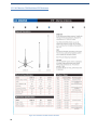
9 LIST OF VHF CHANNELS ................................................................................................................................................. 76
10 COMPLIED STANDARDS ............................................................................................................................................... 77
11 MX535B TECHNICAL SPECIFICATIONS .......................................................................................................................... 78
12 MECHANICAL DRAWINGS ............................................................................................................................................ 79
13.1
AIS ANTENNA SPLITTER ................................................................................................................................................. 87
13 AIS ANTENNA .............................................................................................................................................................. 87
13.2
AC MARINE CX4 MARITIME VHF ANTENNA ..................................................................................................................... 88
14 ABBREVIATIONS AND DEFINITIONS ............................................................................................................................. 89
15 MX535B AIS INSTALLATION – REGISTRATION FORM ................................................................................................... 93
15.1
TROUBLE DESCRIPTION FORM ......................................................................................................................................... 94
LIST OF FIGURES ................................................................................................................................................................ 95
v
1 Introduction
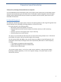
1.1 Safety Instructions
This equipment should be installed according to the instructions found in the installation part of this
manual.
The equipment should not be mounted in a way that exposes it to excessive heat from the sun or
other sources.
The equipment should not be mounted in a flammable environment.
The equipment should not be mounted in a way that exposes it to direct rain or water.
CAUTION!
This equipment contains CMOS integrated circuits. Observe handling precautions to avoid static
discharges which may damage these devices.
Do not open equipment. Only qualified personnel should service the equipment.
1.2 Compass Safe Distance
Transponder unit:
Standard Compass:
Steering Compass:
Display unit:
Standard Compass:
Steering Compass:
95 cm
65 cm
30 cm
14 cm
1.3Copyright Notice
This manual, as well as the software described in it, is furnished under license and may be used or copied
only in accordance with the terms of such license. The content of this manual is furnished for informational
use only, is subject to change without notice, and should not be constructed as a commitment by Navico
Holding AS. Except as permitted by such license, no part of this publication may be reproduced, stored in a
retrieval system, or transmitted, in any form or by any means, electronic, mechanical, recording, or
otherwise, without the prior written permission by Navico Holding AS.
Please remember that existing artwork or images that you want to include in your project may be
protected under copyright law. The unauthorized incorporation of such material into your new work could
be a violation of the rights of the copyright owner. Please be sure to obtain any permission required from
the copyright owner.
1.4 Disclaimer Notice
The information in this book has been carefully checked and is believed to be accurate. However, no
responsibility is assumed for inaccuracies. Simrad reserves the right to make changes without further notice
to any products or modules described herein to improve reliability, function or design.
Simrad does not assume any liability arising out of the application or use of the described product.
1
1.5 Disposal Instructions
The MX535B Transponder and Display shall be disposed according to local regulations regarding
Electronic Waste Recycling in the country the equipment is taken ashore. At time of writing this manual (2012),
there are some common regulations which allies:
Europe:
Directive 2002/96/EC (WEEE) Waste Electrical and Equipment Directive
Equipment is labeled with this symbol:
USA:
Most states have implemented some kind of recycling act, but there is not yet a federal law about
this issue.
Elsewhere:
Follow local regulations regarding disposal of electronic equipment.
1.6 Software Versions
MX535B ------------ V1.00.05
MX510/MX512 --- V3.0
1.7 Ingress protection
Transponder unit: IP56
IPx6
IEC 60945, Exposed
Display unit: IP54
IEC 60945, Protected
2
2 Operation General Introduction
Thank you for purchasing the Simrad AIS Class A transponder.
The Simrad MX535B has been developed to offer you the highest level of performance and durability and we
hope that it will provide many years of reliable service. This product has been designed to meet the highest
possible quality standards and should you encounter any problems with this product, please contact your
local dealer for assistance.
2.1 About AIS in general
The Automatic Identification System (AIS) is based on the IMO regulation for AIS using Self Organized Time
Division Multiple Access (SOTDMA) technology based on a VHF Data Link (VDL).
The system operates in the following modes:
O Autonomous (continuous operation in all areas)
o Assigned (data transmission interval remotely controlled by authority in traffic monitoring
service)
o Polled (in response to interrogation from a ship or authority)
o Silent (listening only, use with caution)
The system is synchronized with GPS time (UTC) to avoid conflict among multiple users. If GPS data is
not available, the system is self-synchronized using the VDL message.
The VHF channels 2087 and 2088 are the main AIS channels in addition to local AIS frequencies. AIS
transponders onboard ships exchange various data as specified by IMO and ITU on either frequency
set up by:
O The frequency management telecommand (DSC)
O Special AIS messages sent from an AIS Base station
O Manual input of special region
The normal transmit power is 12.5 W, but under certain conditions, as during tanker loading
(according to ISGOTT regulation), or the use of regional settings, a low power option (1 W) is
automatically selected.
3
3 Equipment List
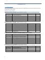
3.1 Standard Supply
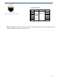
There are four different system packages available for the MX535B AIS systems. Refer to the tables below for
included items in each package.
MX535B AIS system packages
MX535B AIS+MX510 CDU MKD* system (P/N 000-11129-001)
Part No.
985-10631-001
3508-102-70860
510-000-0000
510-100-2001
AN156
000-10232-001
Name
MX535B Transponder Unit
MX535B Operator and Installation Manual
MX510 Display Unit
Mounting bracket, Display unit
GPS Globe Antenna
AIS (MKD) License
Type
AIS
CDU
MKD
Qty.
1
1
1
1
1
1
MX535B AIS+MX512 CDU MKD* system (P/N 000-11130-001)
Part No.
985-10631-001
3508-102-70860
512-000-0000
512-100-1001
510-100-2001
AN156
000-10232-001
Name
MX535B Transponder Unit
MX535B Operator and Installation Manual
MX512 Display Unit
MX512 JUNCTION
Mounting bracket, Display unit
GPS Globe Antenna
AIS (MKD) License
Type
AIS
CDU
MKD
Qty.
1
1
1
1
1
1
1
MX535B AIS+MX512 CDU+MX521A DGPS NAV system (P/N 000-11131-001)
Part No.
985-10631-001
3508-102-70860
512-000-0000
727051
512-100-1001
510-100-2001
AN156
000-10232-001
Name
MX535B Transponder Unit
MX535B Operator and Installation Manual
MX512 Display Unit
MX521A DGPS Smart Antenna
MX512 JUNCTION
Mounting bracket, Display unit
GPS Globe Antenna
AIS License
Type
AIS
CDU
DGPS
MKD
Qty.
1
1
1
1
1
1
1
1
MX535B Upgrade (Upgrade MX512 only) (P/N 000-11129-001)
Part No.
985-10631-001
3508-102-70860
AN156
000-10232-001
4
Name
MX535B Transponder Unit
MX535B Operator and Installation Manual
GPS Globe Antenna
AIS License
Type
AIS
Qty.
1
1
1
1
3.2 Optional Supply
The items below can be ordered separately through us or through a third party supplier.
Part No.
9525-200-80230
Name
CX4 VHF Antenna
Antenna Cable for VHF antenna
Antenna Cable for GPS antenna
Pilot Plug Cable assembly
Antenna Mounting Bracket
Interconnect cable (2x shielded twisted-pair)
MX521 Antenna Cable
Connector Type
PL259
PL259-BNC
TNC-TNC
1”-14 TPI
10-Pin connector
*MKD – Minimum Keyboard and Display – The MX51x CDU does not feature any navigation capabilities hence
the MX antenna is not required. Position data is supplied by the built-in GPS in the MX535B AIS transponder.
5
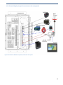
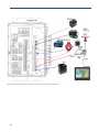
4 MX535 Description
The AIS system consists of two separate units interconnected by 2-Pairs shielded cable. The MX535B
Transponder is the main unit, handling the basic AIS functionality, including sensors and RF functions,
while the M X 5 1 x Display unit is used for setup and display of the AIS data as well as optional
interface to on-board electronics.
Figure 4.1 MX535 System Diagram
6
4.1 Functionality
The main features are: Safety of navigation by automatically exchanging navigational data between ships
(Class A transponders), coast stations, Class B transponders and receiving positional data from
AIS-SARTs (Search and Rescue beacons) and A to Ns (Aids to Navigation).
Class A AIS transmitter and receiver (transponder)
Class B compatible (receives all Class B messages)
Short safety related messages and other short messages
MKD panel Interfaces for AIS compatible radar, ECDIS/ECS/Chart plotter
GPS and VHF antenna separate or combined, for easy installation available
Built-in GPS receiver for time synchronization and backup position
SD-Card slot for future upgrades
The information exchanged between ships using AIS transponders are:
Static data:
MMSI (Maritime Mobile Service Identity) IMO
number (where available)
Call sign and name
Length and beam
Type of ship
Location of position-fixing antenna on the ship
Dynamic data:
Ship’s position with accuracy indication and integrity status UTC
Course over ground (COG)
Speed over ground (SOG)
Heading
Rate of turn (where available)
Voyage related data:
Navigation status (manual input)
Ship’s draught
Hazardous (cargo type)
Destination and ETA (at masters’ discretion)
7
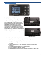
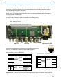
4.2 Transponder Unit
Front view
Side view
The Transponder Unit contains all the core functionality of the AIS system and can function as a separate unit
connected to other display solutions confirming with the AIS message format. It consists of a splash proof
aluminum casing with the following connection possibilities:
VHF antenna and GPS Antenna
External display connections (“Ecdis Port” and “Pilot/Aux Port”)
Sensor connections
DGNSS/DGPS
Beacon receiver connection
Alarm relay
Complies with the environmental requirements specified in IEC 60945 Ed.4 Exposed, and is certified for
IP56 /IPX6. The operating temperature is from -25°C to +55°C and storage temperature from -30°C to +70°C
The receiving section of the Transponder consists of three VHF receiver circuits, for continuous
reception on both AIS channels (configurable from 154 MHz-164 MHz) and the DSC channel (ch70). The
transmitter circuitry is connected to the same antenna terminal and is switched internally.
Functionality for direct reporting with satellites (Long-range AIS broadcast) is implemented and
operates when so configured by the competent authorities.
The internal power supply of the Transponder is galvanically isolated in order to protect the internal circuitry
and operates in a wide voltage input range from 10.8 V–31.2 V. A backup power source can be connected if
available. Automatically switching to backup power source will take place if the main source of power is lost.
8
4.2.1 LED Indicators:
Transmission
Reception Alarm
Status
4.2.2 Main functionality:
Transmit and receive AIS data packets over the VHF link
Receive DSC messages
Provide time and position data from internal GPS
Receive and handle data from external sensors
Provide information about own and other ships positions to the display units, both the MX535B
MX51x Display unit, and to high speed ports like “External Display” and “Pilot/Aux Display”
4.2.3
VHF antenna connector
This is a BNC type antenna connector to be connected directly to a CX4
external VHF antenna to receive and transmit VHF frequencies.
4.2.4
GPS antenna connector
This is a TNC type antenna connector to be connected directly to an
external GPS globe antenna to receive GPS information.
Note: A combination VHF/GPS antenna may also be used with an antenna splitter in place of the separate VHF
and GPS antennas.
9
4.2.5 LAN (Ethernet) Connector
RJ45 type waterproof Ethernet connection (NOT USED)
4.2.6 Multipurpose cable glands
The Transponder Unit is
fitted with 9 multipurpose cable glands for
waterproof, shielded connection with the unit.
There are 3 different sizes
in order for the best
possible fit for different
cable types. All wiring
should be drawn in
shielded cables connected to the chassis of
the Transponder by the
cable glands.
Max Quantity
Min Cable Outer
Ø [mm]
Max Cable Outer
Ø [mm]
Minimum Ø above
braiding [mm]
Recommended use
3
4
2
3.5
4.5
7
7
9
12.5
2
4
5
Sensors
Communication
Power
Table 1: Quantity and specification of multipurpose cable glands
10
4.3 MX510/512 Display Unit
MX51x Front View
The MX51x (MX510 or MX512) Display unit is the user
interface for the AIS system on the bridge. It is used to
configure the MX535B system and to present AIS data
about own and other ships, both graphically and in list
form. The MX510 model is used as an MKD (Minimum
Keyboard and Display) for the AIS, while the MX512 can be
both an MKD as well as navigation unit. The MX51x
Display Unit consists of a splash proof housing with a 6
inch LCD black/white display. Splash proof connections for
Power/Data, AUX, Antenna, USB and LAN are present on
the back side of the unit. The operating voltage range of the
display and AIS transponder is from 10.8 – 31.2 VDC. A
Backup power (12-24 VDC) source can be connected to the
MX535B if available. This will be automatically switched in if
the main source of power is lost.
MX512 Rear View
MX510 (MKD) Rear View
The main features of the MX51x AIS Display Unit are:
• Give the user information about other ships with AIS in the vicinity
• Enable the user to obtain information about other ships and send and receive safety
messages to other ships with AIS Transponders
• Enable the user to configure the AIS System. Alert the user about alarms from the
AIS system
• Pilot Port connection can be done directly to the transponder or to the MX51x
Display Unit
• Provide NMEA data port connection(s) to on-board electronics
• Certified to IP54 and IEC 60945 Ed.4 “Protected”
• Operating temperature from -25°C to +55°C and storage temperature from -30°C to +70°C.
11
5 Operational description
The operational description chapter assumes that the MX535B AIS Transponder and the MX51x display are
fully installed using the instructions found in the Installation chapter.
5.1 Powering the MX535B system
The MX535B turns on as soon as the external 12-24 VDC supply is connected to its terminals. It is
recommended that the external power to the unit be wired to a fuse or a circuit breaker for safety and
convenience. It will take about 1 minute warm-up time before the VHF transmission starts.
The power switch of the MX51x display unit does not control the power to the Transponder. Even if you
turn OFF the MX51x display, the AIS transponder will still be active. Note that the ship list will need some
time to recover when turning the Display unit on again. This is dependent on when the messages from the
different vessels are received. The message logs for sent and received messages will also be lost.
Note that the Transponder unit will issue an alarm when the display is shut down, and there may be no
means to acknowledge this alarm if the display is turned off!
5.1.1 Powering the MX51x display
To turn on the MX51x display, press the power key momentarily. To turn off, press the power key,
then highlight the YES softkey and press the ENT key or you can press and hold down the power key
for 5 seconds.
5.2 AIS General Setup
5.2.1 AIS System Setup
Prior to using the MX535B AIS system, it is necessary to configure the AIS menus under the CFG key of
the MX51x CDU, namely:
• AIS Config
• AIS Static
• AIS Voyage
To access the AIS configuration setups, follow the procedure below.
AIS Config Setup
The MX51x/AIS display was designed to work with several types of class “A” AIS transponder systems.
The “Transponder type:…MX535B” setup allows the operator to customize the MX51x/AIS display to
work with SAAB (R3), ATLAS, NAUTICAST or MX535B transponder models (other selections may
become available in the future).
The “Static Config Update:” setup is used to determine where the AIS configuration can be controlled
from. Two possible selections are the MKD (MX510 or MX512 CDU) or ECDIS. The MKD is the default
setting.
12
Follow the procedure below to select the “Transponder Type” and “Static Config Update” settings:
1. Press the CFG key.
2. Scroll to AIS Config menu.
3. Press the EDIT key (cursor will be on Transponder Type). Default selection is MX535B.
4. Press the ENT to activate the CHANGE softkey to toggle to a different transponder model.
5. If you need to pass control to the ECDIS system, press the Down arrow key to highlight the
“Static Config Update: … MKD” line.
6. Press the ENT key to change to ECDIS (MKD is the default setting).
7. Press the EDIT to exit.
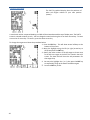
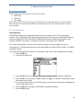
5.2.1.1 AIS Static Setup
The AIS Static Setup contains both the ship’s static data and AIS transponder configuration. This
setup must be done after installation or at any time changes are made to the ship’s AIS
transponder unit.
It is important to note that critical AIS static setup items (such as MMSI, IMO, Ship name & Call
Sign) are password protected. Setup items that require administrator password are indicated in
the Display Field Descriptions below. If an invalid or missing password is used, an alarm is
displayed and the entry will be rejected. Press the ‘Cancel alarm’ softkey to continue.
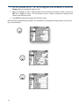
Follow the procedure below to enter the required AIS static information:
1.Press CFG key.
2.Highlight the AIS Static under the ‘Item’ column.
3.Press the EDIT key to start editing the AIS Static setup.
13
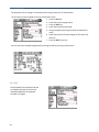
4. The “AIS Connected (Port 5):… No” will be highlighted, press the ENT key to activate the
Change softkey to change the value to “Yes”.
5. Move the highlight to other required setup items and enter the numeric values or press the
ENT key to toggle the value. You will need to use the “admin” password to change critical
values in the AIS Static menu.
6. Press EDIT key when done editing the AIS Static menu.
More AIS Static configuration parameters are available by scrolling down using the down arrow cursor
key as shown below.
14
Note: A total of 37 lines are available under the AIS Static menu. If only 10 lines are listed, the MX51x
may not be communicating with the transponder. Verify that the “AIS Connected” value is set to YES
and the correct transponder type is selected.
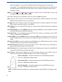
Display Field Descriptions:
AIS, ECDIS, PILOT, Long Range, Ext. GPS Connected: Use the CHANGE softkey by pressing ENT key to
change the value to Yes.
ECDIS, PILOT, Long Range, Ext. GPS Port: Use the CHANGE softkey by pressing the ENT key to scroll
through the port# to which the device is connected. “AIS Port” is pre-selected to NMEA5, LongRange Communication port is NMEA 6, ECDIS is on NMEA 7 and the Pilot port is on NMEA 9.
ECDIS and PILOT Msg Config: Use the CHANGE softkey by pressing the ENT key to change the
communication protocol. EIC protocol is preferred by most AIS Transponder.
Long Range Reply: Use the CHANGE softkey by pressing the ENT key to change value to AUTO,
Manual or Off. In Manual mode, the user is prompted to reply to the Long-Range system when
interrogated. In Auto mode, the MX51x/AIS will automatically send a reply when interrogated.
In Ext. Appl (External Application) mode, the MX51x/AIS passes the request onto the highspeed ports (ECDIS & Pilot), and waits for their response to prepare answer back to long range
system.
MMSI: A 9-digit Maritime Mobile Service Identity number used for identification of ship and message
(administrator password required).
Note: When editing critical transponder setup items use the “admin” password.
Ship: Enter the vessel name up to 20-characters (administrator password required). The symbol
ããããã (or blank) indicates name is not available.
Call Sign: Enter the 7-character vessel’s call sign (administrator password required). The symbol ãããã
(or blank) indicates call sign is not available.
IMO Number: Enter the 9-digit IMO identification number when available (administrator password
required).
Chnl A & B-TX Mode: Use the CHANGE softkey by pressing the ENT key to select between Transmit
and Silent (administrator password required).
External GPS Ant: You can designate the external GPS to be a primary or secondary source of GPS
position. Default value is SECONDARY.
15
Passthru NMEA: Use the CHANGE softkey by pressing the ENT key to change the value to YES if you
want the NMEA data from the antenna to be passed through to the data ports. Normally set to
NO.
MX Ant (A, B, C & D): This sets the location of the PRIMARY source of GPS position antenna. Specify
the position location (in meters) See the drawing below.
External GPS Ant (A, B, C, D): This sets the location of the Ext. GPS antenna (a.k.a. Secondary) in
meters (similar to the primary GPS Ant A,B,C,D).
AIS GPS Ant A, B, C, D: Specify the position offset of the GPS globe antenna used in the MX535B AIS
transponder (administrator password required).
Data Timeout: Allows you to change the time the AIS targets will stay on the MX51x screen to match
that of the ECDIS or RADAR AIS targets. Pre-set value is 360 seconds.
Sensor 1 Baud Rate: Controls the baud rate of the MX535B input
Sensor Channel 1. 4800 baud is default speed.
Sensor 2 Baud Rate: Controls the baud rate of the MX535B input
Sensor Channel 2. 4800 baud is default speed.
Sensor 3 Baud Rate: Controls the baud rate of the MX535B input
sensor Channel 3. 4800 baud is default speed.
NOTE: Changing the baud rate requires re-cycling the power to the
MX535B for the change to take effect.
How to change transponder settings under the AIS Static configuration using the
administrator password:
1. Press the CFG key.
2. Scroll down to AIS Static menu.
3. Press the EDIT key to bring up the cursor.
4. Move the cursor down to MMSI, Ship or Call Sign field.
5. Move the highlight to SET AIS PASSWORD softkey using the left (or right) arrow key.
6. Press the ENT key to commence entry of the “admin” password using the procedure below:
To enter the password “admin” do the following:
a. Press the #1 key to bring up the lowercase letter “a”.
b. The cursor will advance to the next character.
c. Press #2 key 1 time to bring-up the letter “d”.
d. Press the #5 key one time for letter “m”.
e. Press the #3 key 3 times for letter “i”.
f. Press the #5 key 2 times for letter “n”.
g. Highlight the Done softkey, then press the ENT key.
7. Move the cursor to the MMSI number and enter the desired value using the numeric keypad.
8. Move the highlight to “Ship:” and spell out the name of the vessel (up to 20 alphanumeric
characters).
9. Move the highlight to “Call Sign:” and enter up to 7 characters.
16
10. To change other setup items use the cursor key to scroll down or up and enter the number or
name required.
11. At the end of editing, press the EDIT key to exit.
5.2.2 AIS Displays
5.2.2.1 AIS Function Key
Several AIS display pages are available under the AIS key. Pressing the AIS key repeatedly will scroll
through the following AIS screens (paging can also be done by using the left or right arrow keys after
pressing the AIS key), namely:
AIS1 - OWN SHIP DATA
AIS2 - REMOTE SHIP LIST
AIS3 - RX SAFETY MSGS
AIS4 - TX SAFETY MSG
AIS5 - TX SAFETY LIST
AIS6 - REGIONAL AREAS
AIS7 - LONG RANGE LIST
AIS9 - AIS STATUS
AIS11 - SECURITY LOG
AIS12 – REMOTE SHIP EPFS
AIS13 – REMOTE SHIP DATA
AIS 1 – OWN SHIP DATA
This screen shows the ship’s information transmitted by the AIS transponder. Information such
as ship’s name, MMSI#, call sign, IMO#, ship type/cargo, navigation status are all configured
under the AIS Static setup, while the destination, Nav stat, ship/cargo type and ETA are taken
from the AIS Voyage setup. It also indicates which GPS position is used and its antenna offset
data.
17
Display Field Descriptions:
Name:
Vessel’s name.
MMSI:
Maritime Mobile Service Identity number used for identification of ship and message.
Ship/Cargo Type: Ship & Cargo Type (see table A-1 for values).
AGE:
Age of the information on the display, in seconds.
Nav Stat:
Navigation status as entered in AIS Voyage setup.
CALL SIGN: Assigned radio call sign.
IMO:
International Marine Organization number.
GPS Source: Source of the GPS information in use. The choices are Primary (MX421 or MX525 smart
GPS sensors), Secondary (external GPS attached to the MX420 CDU), and Backup
(Transponder GPS).
Lat/Lon:
Position fix of the GPS in use.
GPS Ant Pos: In-use GPS Antenna location (A, B, C & D values see below) with reference to aft of bow
and port or starboard of centerline.
HDG:
Gyro reading, in degrees.
COG:
Course Over Ground (degrees).
ETA:
Estimated time of arrival (date & time).
ROT:
Ship’s Rate-Of-Turn, in degrees per minute.
SOG:
Speed Over Ground (knots).
Destination: Operator entered destination under the AIS Voyage setup screen.
GPS Antenna Offset Diagram
18
5.2.2.2 MX510/512 Display Unit Menu System
AIS 2 – Remote Ship List
This display shows a list of target ships equipped with AIS transponders that are being tracked within
VHF range. The list can be sorted by range from your location or by bearing. Because of space
limitation, only 7 vessels are displayed per page. More target ships can be displayed by pressing the
down arrow key repeatedly. You may also press the EDIT key and use the MORE softkey to display
the next screen or go back to the previous screen.
There are five columns are avialable indicating the TGT index #, MMSI, RNG, BRG relative to your position
and name of the ship when available.
To bring up more targets, press the down arrow key or press the EDIT key to bring up the softkeys.
You can sort the targets by range or by bearing from your ship. You can scroll left or right by
highlighting the
or
softkey and pressing the ENT key to list other ships around you in
15 degree increments. Highlighting the MORE softkey and pressing the ENT key will allow you to go
to the next screen of targets or go back to the previous screen.
Display Field Description:
TGT: Target number of MMSI database for quick vessel access. TGT corresponds with vessels shown
on the PLOT3 display. The icon indicates the vessel type.
AIS2 icons and their meaning:
(Flag) Class A or Class B vessel
Base Station
19
Search and Rescue (SAR)
Aids to Navigation
MMSI: Defines the unique vessel ID.
RNG: Range (NM) from your ship to the remote vessel.
BRG: Bearing (Degrees True) from your ship to the remote vessel.
NAME: Name of remote vessel (name is transmitted more seldom than the MMSI#).
Softkey Descriptions:
- User can choose to have a list of MMSIs displayed in 15 degrees increments
- Shift bearing search by 15 degrees left
- Shift bearing search by 15 degrees right
- User can choose to display the MMSIs by distance relative to the vessel
- Additional softkeys are available
- Shows the next 7 MMSIs
- Shows the previous 7 MMSIs
- Return to the original softkey setup
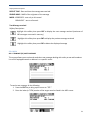
5.2.3 AIS 3
AIS3 - RECEIVED (RX) SAFETY MESSAGES
This display stores all AIS safety messages broadcast by other AIS stations or messages addressed to
your ship. The MX51x AIS display will retain the last 100 messages received. You have the option to
manually delete the message by pressing EDIT key then select the
softkey and press ENT.
When the number of messages exceeds 100, the oldest message will be overwritten.
20
Display Field Descriptions:
RECEIPT TIME - Date and time the message was received
SENDER MMSI - MMSI of the originator of the message
MODE- ADDRESSED - sent only to this vessel
BROADCAST - sent to all vessels
Text Message received.
Softkey Descriptions:
Highlight this softkey then press ENT to display the next message received (maximum of
100 messages are stored in memory)
Highlight this softkey then press ENT to display the previous message received
Highlight this softkey then press ENT to delete the displayed message
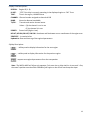
5.2.4 AIS 4
AIS 4 - TRANSMIT (TX) SAFETY MESSAGE
This screen allows you to write and send short text messages dealing with safety at sea and broadcast
it to all AIS equipped vessels or address it to a specific vessel.
To send a text message, do the following:
1. Press the EDIT key to bring up the cursor to “TGT:”
2. Enter the index (or TGT#) number of the target vessel as listed in the AIS2 screen.
21
3.
4.
5.
6.
7.
The MMSI field will be populated with the MMSI# for the selected vessel.
Scroll down to the text string field and type the message using the alphanumeric keypad.
Highlight the “Tx MSG” softkeys using the left (or right) arrow key.
Press the ENT key to transmit.
Press the EDIT key to exit.
Display Field Descriptions:
OUTPUT CHNL - This field specifies which channel is to be used for sending the safety message.
User can scroll through four different settings. The data displayed in this field can be altered
using the TOGGLE CHNL softkey. Start by pressing the EDIT key, highlight the TOGGLE CHNL
softkey then press the ENT repeatedly to toggle through 4 choices, namely: Auto Select,
Channel A, Channel B or Both A&B. Default value is Auto Select.
MODE- This field shows whether the message is to be sent to a specific vessel (addressed) or to all
(broadcast). Pressing the TOGGLE MODE softkey will select either ADDRESSED or
BROADCAST
TGT - This requires entry of the TGT index number which is directed to the appropriate MMSI.
MMSI - This field indicates the MMSI number related to the target (TGT) number selected to send
the text message to.
TEXT String - Enter the text message to be sent using the alphanumeric keypad.
Softkey Descriptions:
The softkeys can be displayed by pressing the EDIT key first.
- Highlight this soft key then press the ENT key to change the channel. The following
values are available:
AUTO SELECT - transponder determines on which channel to use
CHANNEL A - broadcast on channel A only
CHANNEL B - broadcast on channel B only
BOTH A & B - broadcast on both channels.
- Toggles the output mode to either ADDRESSED or BROADCAST. When addressed is
selected, the MMSI number will be displayed automatically when the TGT number is
specified.
-Transmits the text message.
- Use this softkey to bring up more softkeys.
- Sends the number of people to the transponder for transmission.
- Sends a command to the transponder to transmit the “Height Over Keel” as set in the
AIS Static configuration screen.
22
- To go back to the previous softkeys
Note: The softkeys can be activated by highlighting it (using the left or right arrow keys) and then
pressing the ENT key.
WARNING!
Use of AIS text messages between ships must not be used to avoid collisions when time is critical. AIS systems
are not required to have an audible alarm to indicate the arrival of all text messages.
The use of AIS text messaging does not relieve the vessel of other requirements, such as the Vessel Bridge-toBridge Radiotelephone regulations or of the requirements to sound whistle signals and display lights or shapes in
accordance with the International or Inland Navigation Rules.
Usage During Emergencies - With respect to using AIS safety related text messages in emergency situations,
users must be aware that they may not be received, recognized or acted upon as Global Maritime Distress
Safety Systems (GMDSS) messages would be by the Coast Guard, other competent authorities or maritime first
responders. Thus AIS must not be relied upon as the primary means for broadcasting distress or urgent
communications, nor used in lieu of GMDSS such as Digital Selective Calling radios which are designed to process
distress messaging. Nonetheless, AIS remains an effective means to augment GMDSS and provides the added
benefit of being ‘seen’ (on radar or chart displays), in addition to being ‘heard’ (via text messaging) by other AIS
users within VHF radio range (Ref: USCG Safety Alert 05-10).
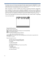
5.2.5 AIS 5 - TX Safety List
This display allows you to review the safety messages you transmitted under the AIS 4 (TX SAFETY
MSG) display.
Display Field Description:
Transmit Time - Time the message was transmitted
Mode - Whether it was addressed or broadcast
Message Field
Softkey Description:
- View next message
- View previous message
23
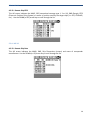
5.2.6 AIS 6 - REGIONAL AREAS
Two VHF and one DSC receiver channels have been designated for AIS use worldwide.
These frequencies are:
• AIS 1 (Channel 87B, 161.975 MHz, (2087)
• AIS 2 (Channel 88B, 162.025 MHz, (2088)
• DSC (Channel 70, 156.525 MHz)
Under normal masterless operation, the MX535B AIS transponder operates autonomously with other
ships or AIS base stations using the AIS1 & 2 frequencies. When entering areas controlled by a
competent authority (i.e. Coast Guard) under Vehicle Tracking System (VTS) rules, the MX535B AIS
transponder can be polled and controlled by the VTS station. In this situation, data communication
between ship-to-ship and ship-to-shore stations is done through the DSC frequency (channel 70). All
VTS related activities are happening without any user intervention.
The controlling VTS base station schedules all ship’s data transmission and provides the regional
parameters shown in AIS 6 display, such as:
• Operating frequency, bandwidth and mode of Channel A & B receivers
• Northeast and Southwest corner coordinates of the region
• Zone size
• Date and time tag
These parameters are stored in the memory bank of the AIS transponder and can be displayed in the
MX420/AIS CDU. Up to eight regions can be stored by the transponder. The AIS constantly checks
the stored region boundaries and compares it to its own position. If the distance to the region
boundaries is greater than 500 miles from its own position or the time tag was older than five weeks,
those stored regions will be erased from memory.
The operator (administrator) has the option to do a full or partial editing of the regional parameters
when needed. The conditions below have to be observed when editing:
• Use the correct channel numbers (see table A-1 or in the AIS card)
• Latitude difference should be no less that 20 NM or larger than 200 NM
• Longitude difference should be no less than 20 NM or larger than 200 NM
• The zone size should be no less than 1 square mile or larger than 8 square miles
• Distance to the zone is less than 500 NM from you current position
Manual entries violating any of the above conditions will be rejected by the AIS transponder
without notifying the operator. If the region memory is full, the oldest regional memory will be
replaced by a newly accepted one.
24
Display Field Descriptions:
REGION - Region ID (1- 8)
IN USE “YES” if the ship is currently operating in the displayed region or “NO” if not
TIME Time in the region, HH:MM format
CHANNEL - Channel number assigned to channels A & B
BAND Normal or Narrow bandwidth
TX/RX Transmit and receive channel status
Values: (N) the channel is not in use
(Y) the channel is in use
POWER - Power level (High or Low)
NE LAT, NE LON, SW LAT, SW LON - Northeast and Southwest corner coordinates of the region area
ZONE SIZE - in nautical miles
Updated at: Date and time tag of the regional parameters
Softkey Descriptions:
- softkey used to display information for the next region
- softkey used to display information for the previous region.
-request new regional parameters from the transponder.
Note: The MX51x MKD will inform the operator if the zone size or delta Lat/Lon is too small. Also,
the vessel’s position must be within 500 NM of the region or the AIS will not accept the input.
25
5.2.7 AIS 7- LONG RANGE (LR) DISPLAY
This display shows a list of queries by other AIS stations going through the INMARSAT-C or other
long-range communication systems. The MX51x can be set to respond to long-range interrogations
either automatically, manually (default) or by external application.
When the setting is in AUTO, the MX51x will provide the requested information automatically.
When in MANUAL, the operator needs to highlight the SEND REPLY softkey and press the ENT key to
reply. The soft-keys can be brought up by pressing the EDIT key. Every time a long range query is
received, the MX51x will pop-up a message window accompanied by an audio alarm. When in “Ext
Appl” mode the external application will need to respond to the MX51x with permission to reply.
To look at the long-range list, press the AIS key several times until it shows the AIS 7 Long Range
screen (as shown below).
Display Field Descriptions:
ID- Query index number (0-99)
TIME - Time when the long-range message was received (HH:MM)
MMSI- ID of requesting station
REPLY- YES-means the query has been answered
NO - means no reply has been sent yet
ABCEFIOPUW - an ‘X’ under each letter heading denotes the information requested in the
interrogation message
Reply message description:
A - Ship’s name, call sign and IMO number
B - Date and time of message composition
C - Position
E - Course over ground
F - Speed over ground
G - Destination and Estimate Time of Arrival (ETA)
H - Draught
I - Ship/Cargo type
J - Ship’s length, breath, type
K - Persons on board
26
Softkey Descriptions:
Pressing the EDIT key will bring up the following softkeys:
This softkey is used to advance the display to show the next page of information.
This softkey is used to show the previous page of information.
This softkey becomes available only when Long Range inquiry is received,
otherwise it will not be there.
To reply to long-range interrogation in manual mode, do the following:
1. Press the AIS key several times until the AIS 7 screen appears.
2. Press the EDIT key to show the softkeys.
3. Highlight SEND REPLY softkey and press ENT key. A pop-up window requesting for
an ID number will appear.
4. Enter the listed ID number to reply to.
5. Press EDIT key to exit.
5.2.8 AIS 9 – AIS STATUS
This display shows the operational status of the AIS transponder.
The table below is a list of possible AIS related messages generated by the transponder:
AIS Related Messages
AIS: UTC Clock Lost
AIS: Primary External DGNSS In Use
AIS: Primary External GNSS In Use
AIS: Backup DGNSS In Use (Beacon)
AIS: Backup DGNSS In Use (Msg 17)
27
AIS: Backup GNSS In Use
AIS: Backup SOG/COG in Use
AIS: HDG Data In Use
AIS: ROT Data In Use
AIS: Channel Management Parameters Changed
AIS: Secondary External DGPSNN In Use
AIS: Secondary External GPSNN In Use
AIS: Secondary External SOG/COG In Use
AIS: UTC Clock OK
AIS: Boot Sequence In Process
5.2.9 AIS 11
AIS 11 – Security Log
This AIS screen shows the list of Dates and Times the AIS transponder has been out of operation. Use
the DOWN (or UP) arrow key to scroll through the list. Pressing the EDIT key will bring up the
“REFRESH” softkey. Press the ENT key to refresh the screen.
28
5.2.10 AIS 12
AIS 12 - Remote Ship EPFS
This AIS screen indicates the MMSI, SRC (transmitted message type 1, 3 or 18), RNG (Range), EPFS
(Electronic Position Fixing System) or source of position used by the target ships (i.e. GPS, GLONASS,
etc.). Use the DOWN (or UP) arrow key to scroll through the list.
5.2.11 AIS 13
AIS 13 - Remote Ship Data
This AIS screen indicates the MMSI, RNG, Ship Dimensions (meters) and name of transponder
manufacturer. Use the DOWN (or UP) arrow key to scroll through the list.
29
5.3 PLOT 3 Screen:
The PLOT 3 graphical display plots the positions of
other AIS targets relative to your own position
(center).
A vessel with neither a reported heading nor COG will be oriented toward the top of display area. The PLOT 3
screen is oriented as North Up only. You can change the zoom level using the UP or Down arrow keys. To zoom
out use the UP arrow key. To zoom in, press the down arrow key.
To change the target vessel # use the procedure below:
1. Press the EDIT key. This will show several softkeys at the
bottom of the screen.
2. Move the highlight using the left (or right) arrow key to
GOTO and press the ENT key.
3. Specify the index number of the AIS target as shown next
to the AIS icon targets in the PLOT 3 or listed in the AIS 2
screen. The data field will show the AIS parameters for
that target chip.
4. You may also highlight the + (or -) then press the ENT key
to sequentially bring up the data of available targets.
5. Press the EDIT key to exit.
30
Different types of targets are displayed with different icons
Active Vessel
If the CPA/TCPA system is activated, ships on collision course are displayed with a red
color and double thickness of the lines.
Own ship is indicated in the same way as other ships, but is always in center.
Sleeping target
Smaller symbol than “Active Vessel” without a beam line
Sleeping targets are defined based on either:
Range more than X Nautical miles
Class B
Activation can be either of the definitions above and can be visible or not.
AIS base station
A to N
An Aid to navigation buoy indicating that it is off position is indicated with a red
color.
AIS SART. Will be displayed with a red color.
AIS TEST will be displayed with normal color.
SAR Aircraft
Own ship
31
5.4 AIS Voyage Settings
Configuring the AIS Voyage
The AIS Voyage setting contains all the ship data to be entered or changed before or on each
voyage. In order for the AIS system to function correctly, it is important to keep these parameters
up to date. Information about the ship’s destination, ETA time and date, number of passengers/
crew and type of vessel are entered in the MX51x for each voyage or whenever needed.
AIS Voyage Parameter Descriptions:
Nav Stat - This setup item controls the AIS status icon shown on the upper-right corner of the
display. See section below for all available nav-stat icons and descriptions.
Destination - Enter the 20-character destination name.
ETA Time - Enter the estimated time of arrival at the desired destination.
ETA Date - Enter the estimated date of arrival at the desired destination.
Draught - Enter draught height in meters.
No. of People - Enter the number of people on board (1-8191).
Ship/Cargo Type - Use the softkey to toggle ship cargo choices. Refer to table A.2 for possible
ship type values (0-255).
Softkey Descriptions:
- Use the CHANGE softkey to toggle through various values available in the field.
-Use the SEND PEOPLE softkey to send the broadcast the number of people on-board.
Navigation Status Icons and Descriptions:
Vessel underway
Not Defined
32
Vessel not commanded, limited maneuverability, limited by draught, aground or
reserved for future use
Ship is anchored or moored
The MX51x display is not communicating with the MX535B transponder.
Note: The displayed icons located on the top-right corner of the screen is set to blink off and on
every 3 seconds to allow the operator to see what is behind it and is not considered an alarm
condition. An every second blinking is an alarm condition.
To change the AIS Voyage settings, do the following:
Press the CFG key.
Scroll down to AIS Voyage menu.
Press the EDIT key to bring up the cursor on the right box.
Scroll to the item you want to change.
Using the left (or right) arrow key to move the softkey highlight to the CHANGE softkey.
Press the ENT key to activate the CHANGE softkey to parse through the available settings or use
the alphanumeric keypad to enter name of place or numbers.
7. Press the EDIT key to accept entry and exit.
1.
2.
3.
4.
5.
6.
Note: Normal VHF transmission power is 12.5 Watts. Low Power is 1 Watt if Vessel type selected is
“Tanker”, Speed is below 3 knots and Navigation Status is “Moored”.
33
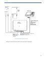
5.4.1 Table for ID Numbers
Table A.2 ID Numbers Used in AIS
Identifier No.
Special craft
50
Pilot Vessel
51
Search and rescue vessel
52
Tugs
53
Port tenders
54
Vessels with anti-pollution facilities or equipment
55
Law enforcement vessels
56
Spare – for assignments to local vessel
57
Spare – for assignment to local vessel
58
Medical transports (as defined in the 1949 Geneva Conventions and
Additional Protocols)
Ships according to Resolution No. 18 (Mob-8.3)
59
Other Ships
First digit (*)
1-reserved for
future use
2-WIG
Second Digit (*)
First digit (*)
Second digit (*)
0-All ships on the type
-
0-Fishing
1-Carrying DG, HS, or MP
IMO hazard of pollutant
category A.
2-Carrying DG, HS, or MP
IMO hazard or pollutant
category ,
3-Carrying DG, HS, MP
IMO hazard or pollutant
4-Carrying DG, HS, or MP
IMO hazard or pollutant
category C.
5-reserved for future use
-
1-Towing
3-vessel
2-Towing and length of the
tow exceeds 200m or breadth
exceeds 25m
3-Engaged in dredging or
underwater operations.
4-Engaged in diving
operations
6-Passenger
ships
7- Cargo ships
6-reserved for Future use
-
5-Engaged in Military
Operations
6-Sailing
7-reserved for Future use
-
7-Pleasure craft
8-Tankers
8-reserved for Future use
-
8-reserved for future use
3-see right
column
4-HSC
5-see above
-
9-Other types
9-No additional information
9-reserved for future use
of ships
DG: Dangerous Goods
HS: Harmful Substances
MP: Marine Pollutants
(*) Note: The identifier should be constructed by selecting the appropriate first and second digit
34
5.4.2 Navigational Status
The options available for the navigational status are as follows:
Vessel not under command means a vessel which through some
exceptional circumstance is unable to maneuver as required by
these Rules and is therefore unable to keep out of the way of
another vessel.
Vessel restricted in her ability to manoeuver means a vessel
which from the nature of her work is restricted in her ability to
maneuver as required by these Rules and is therefore unable to
keep out of the way of another vessel. The term “vessels
restricted in their ability to maneuver” shall include but not be
limited to:
o
o
o
o
o
o
A vessel engaged in laying, servicing or picking up a navigation mark, submarine cable or
pipeline;
A vessel engaged in dredging, surveying or underwater operations;
A vessel engaged in replenishment or transferring persons, provisions or cargo while
underway;
A vessel engaged in the launching or recovery of aircraft;
A vessel engaged in mine clearance operations;
A vessel engaged in a towing operation such as severely restricts the towing vessel and her tow
in their ability to deviate from their course.
Vessel constrained by her draught means a power-driven vessel which, because of her draught in
relation to the available depth and width of navigable water, is severely restricted in her ability to
deviate from the course she is following.
Fishing means any vessel fishing with nets, lines, trawls or other fishing apparatus which restrict
maneuverability, but does not include vessel fishing with trolling lines or other fishing apparatus which do
not restrict maneuverability.
Sailing means vessel under sail provided that propelling machinery, if fitted, is not being used.
Under way means vessel is moving under power.
Moored or Anchored is used when the vessel is anchored or tied at the dock.
Not Defined (Default) is used when MX535B is delivered from factory. Then none of above selections is
made.
35
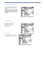
5.4.3 Destination
The destination of the voyage is to be entered here using a maximum of 20 characters.
Use the alpha-numeric keypad to enter the destination name:
1. Press the CFG key.
2. Scroll down to AIS Voyage menu.
3. Press the EDIT key.
4. Scroll down to Destination field.
5. Using the alphanumeric keypad, spell the destination
name.
6. Scroll down to other field to change the ETA time, ETA
date, etc.
7. Press the EDIT key to exit.
You can verify the changed voyage data by pressing the AIS key to bring up AIS1 screen.
5.4.4 ETA
The Estimated Time and Date of Arrival
are displayed to other AIS units and
should be updated if the expected
schedule is changed.
36
5.4.5 Persons Aboard (optional)
This parameter indicates the number of
persons aboard the ship at the given
moment.
This parameter is not sent to other ships
or base stations, only through the Long
Range Port which is normally not used
(in 2011).
5.4.6 Cargo Category
Identifies the type of cargo,
depending on the ship class.
See Table on page 36
for reference.
5.4.7 Draught
The Draught parameter specifies the
maximum depth of the ship in meters.
37
6 Installation
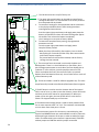
6.1 Mechanical Mounting
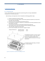
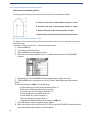
6.1.1 Transponder unit
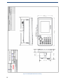
Use the standard Mounting Kit. For dimensions and positioning of holes see Figure 14-1 MX535B
Transponder Unit- mechanical dimensions.
When selecting a mounting location for the Transponder the following guidelines apply:
1. Keep the transponder out of direct sunlight.
2. Do not mount the transponder where it can be directly exposed to seawater as corrosion then
may appear and cause leakage.
3. The unit must not be mounted near exhaust pipes and vents.
4. Even though the transponder is a robust unit, it is advised that it should be mounted were shock
and vibration are minimal.
5. Unit shall not be located near electromagnetic field generating equipment.
6. Leave sufficient space at the sides and top of the unit for maintenance and repair.
Also leave slack in cables for the same reason.
7. Do not mount transponder unit too close to a magnetic compass:
Compass safe distance:
Standard Compass:
Steering Compass:
95 cm
65 cm
The MX535B transponder unit can be mounted
in all directions, either on a wall, roof or floor.
The unit is very robust and made of cast
aluminum coated with black paint for best type
of protection.
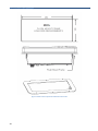
For detailed mechanical drawings, see chapter
12, ”Outline Drawings”.
Figure 6.1 Transponder Unit, exploded view. Opening of outer lid.
38
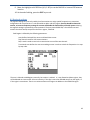
6.1.2 MX51X Display Unit
The display unit can be installed as bracket mounted or flush mounted in a panel. Installation shall be
near the conning position.
When selecting a mounting location for the Display Unit the following guidelines apply:
1. Do not mount the display unit where it can be directly exposed to seawater as corrosion
then may appear and cause leakage.
2. The unit must not be mounted near exhaust pipes and vents.
3. Even though the transponder is a robust unit, it is advised that it should be mounted were
shock and vibration are minimal.
4. Unit shall not be located near electromagnetic field generating equipment
5. Leave sufficient space at the back for connection to necessary cables.
6. Do not mount transponder unit too close to a magnetic compass:
Compass safe distance:
Standard Compass:
Steering Compass:
30 cm
14 cm
6.1.2.1 Bracket Mounting
Figure 6.2 Bracket mounted MX51x display unit and bracket mount
When display unit is mounted overhead, it might be necessary to adjust Contrast. This can be done by using
the procedure below:
1. Press the CFG key.
2. Scroll down to “Lighting” menu.
3. Press the EDIT key.
4. Change the contrast by using the left or right arrow keys.
5. Press the EDIT key to exit.
For detailed mechanical drawings, see chapter 12 Outline Drawings.
39
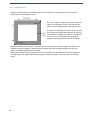
6.1.2.2 Flush/ Panel Mounting
Figure 6.3 Flush mount requirement and flush mount frame
40
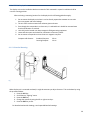
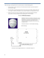
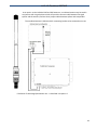
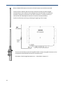
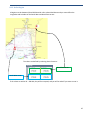
6.1.3 Antennas
As a general rule, longer horizontal distances to other antennas will minimize the interference and
improve reception on all antennas.
Minimum distance is described in the figures below:
Other VHF antenna or
GPS antenna
VHF antenna for AIS:
>10 meters
Figure 6.4 Horizontal separation distance.
VHF antenna for AIS:
VHF antenna for AIS:
See subchapters
below for detailed
description
>2.5 meters
Other VHF
Antenna
>2.5 meters
>0, 5 meters
GPS Antenna
>0, 5 meters
>0, 5 meters
Figure 6.5 Vertical separation and distance from mast or other object of metal. For best isolation between antennas, place directly
underneath with no horizontal separation.
41
6.1.3.1 GPS Antenna
When selecting a mounting location for the antenna, keep in mind the following points.
1. Select a location out of the radar beam. The radar beam will obstruct or prevent reception of
the GPS satellite signal.
2. There should be no interfering object within the line-of-sight to the satellites. Objects within the
line-of-sight to a satellite, for example a mast, may block reception or prolong acquisition time.
3. Mount the antenna unit as high as possible to keep it free of interfering objects and water
spray, which can interrupt reception of GPS satellite signal if the water freezes.
6.1.3.1.1 GPS Globe Antenna
MX535B is delivered as standard with GPS globe antenna
(P/N AN156). The stainless steel stand and antenna coax
cable with TNC connectors in both ends for direct
connection between transponder and antenna are not
included in the kit.
The antenna mount is 1”-14 TPI standard mounting.
Outline Drawings
Calculation of cable length/attenuation etc… is described in chapter 6.2
42
6.1.3.1.2 Combined VHF/AIS
As an option to the individual VHF and GPS antennas, a combined antenna may be used in
conjunction with a signal splitter which will provide a common cable between the signal
splitter and the antenna, and two short jumper cables between splitter and transponder.
The combined antenna is delivered with a mounting bracket to be mounted on a mast.
Calculation of cable length/attenuation etc… is described in chapter 6.2
43
6.1.3.2 VHF Antenna
When individual GPS antenna is used, the CX4 VHF antenna must also be connected.
Location of the mandatory AIS VHF-antenna should be carefully considered. Digital
communication is more sensitive than analogue/voice communication to interference
created by reflections in obstructions like masts and booms. It may be necessary to
relocate the VHF radiotelephone antenna to minimize interference effects.
Install the VHF antenna referring to drawings in beginning of this chapter
The antenna should be connected using RG214 cable or better using BNC connector on the
transponder end and PL259 connector on the antenna end.
Calculation of cable length/attenuation etc… is described in chapter 6.2
44
6.2 Cabling
All outdoor installed connectors on coaxial cables should be fitted with preventive isolation such as
vulcanizing tape to protect against water penetration into the antenna cable.
Coaxial cables should be installed in separate signal cable channels/tubes and at least 10 cm away from
power supply cables. Crossing of cables should be done at right angles (90°). The minimum bend radius of
the coaxial cable should be 5 times the cable's outer diameter.
The cables should be kept as short as possible to minimize signal attenuation.
The type of cables used onboard vessels should be:
o
o
Halogen free
Fire resistant or Flame retardant type
o
Low smoke
6.2.1 GPS antenna
The table below gives recommendations on cables that can be used for the GPS antenna
connections:
Type
RG58
Attenuation
@1.5 GHz
(dB/100 m)
90
RG214
35
RG225
30
Remark
Default for use if length < 20 m and
antenna = An156
If combined GPS/VHF antenna from either AC-Marine, Procom
or Comrod is used, this or better can be used
Cable with lower loss recommended for cable runs >30
meters
For optimum performance of the transponder approximately +10 dB gain should be available when the
cable attenuation has been subtracted from the GPS antenna preamplifier gain. Note that Procom
AIS2/GPS and Comrod AC17-AIS are combined VHF/GPS antennas and additional attenuation from
connectors / diplexer must be taken in consideration. Some examples below:
Cable Type
Antenna
RG58
RG214
AN156
AN156
Comrod AC17-AIS
AC Marine VHF/GPS-B
AN156
Comrod AC17-AIS
AC Marine VHF/GPS-B
RG225
Preamplifier Gain
(dB/100 m)
30
28
20
18
28
20
18
Recommended cable length (m)
<20
10-30
10-20
10-20
10-40
10-30
10-30
45
6.3 Wiring and Connections
The table below shows the attenuation on the VHF frequencies with different cable types:
Cable Type
RG214
RG225
Attenuation @150
MHz (dB/100 m)
7
8
Diameter (mm)
Weight (kg/100 m)
10.8
10.9
18.5
23.3
Example: A RG 214 cable with length of 40 meters will have an attenuation of 2.8 dB.
Please keep the cables as short as possible, and be aware that 3 dB losses mean only half the output
power. If you have a transmitter delivering 12.5 W, and you have 3 dB losses in the cable, only 6.25
Watts will be at the antenna.
6.3.1 Cable between MX535B Transponder and MX51x Display Unit
The cable connecting the MX535B Transponder and the MX51x Display unit is a double twisted-pair cable
with individual shielding. Connections to the MX51x can be done easily through the junction box terminals
as shown below for the MX512 and MX510 display models.
Figure 6.6 Wiring diagram between the Transponder and the MX512 Display Unit (port 5)
Figure 6.7 Wiring diagram between the Transponder and the MX510 Display Unit (port 2)
46
6.3.2 Wiring Figure
Figure 6.8 Block diagram of typical connections
Wiring and connection of Antennas (GPS + VHF) are described in chapter 6.1.3
47
6.3.3 Transponder
In order to connect all sensors and external connections to the Transponder Unit, the lid must be removed by
removing the screws on top of the unit. Pay attention to the seal gasket on the inside of the lid and the small
O-ring positioned on the center screw. These gaskets need to be in place when mounted in order to keep the
unit waterproof. When the lid is off, the connections to sensors, ECS etc… can be made. The inner lid shall not
be removed by user.
Figure 6.9 Transponder with lid removed, lid screws highlighted
48
6.3.4 Pictorial display of typical connections to the transponder
Figure 6.10A: MX512 to MX535B transponder, dashed lines show options
49
Figure 6.10B: MX510 to MX535B transponder connection, dashed lines shows options
50
6.3.5 Label in transponder with connection tables
Label:
Connections table (Except power):
Figure 6.11 Label inside transponder with corresponding table showing details about each connection. It is colored to differentiate
sensors, display/pilot, alarm and DGNSS beacon interface
51
6.3.6 Power Connection
Table showing connection of main and backup power - See also Figure 8-10
Connection
P1
P2
P3
P4
P5
P6
Function
GND (Chassis)
MAIN
0V
MAIN
12 - 24 VDC
GND (Chassis)
BACKUP 0 V
BACKUP 12 – 24 VDC
Allowed voltage levels of the power supply to be connected with the transponder:
Minimum = 10.8 Volt and Maximum = 31.2 Volt
Recommended cable diameter: 2.5 – 4 mm2
6.3.7 Sensor Connections
Sensors like GPS, Gyro, Speed log etc… may be connected to the 3 different sensor inputs in the
MX535B Transponder unit.
Figure 6.12 Sensor Terminals
Recommended cable diameter: 0.25 - 2.5 mm2
#
1
2
3
52
In/
Out
In
In
Type
IEC61162-1
(RS422)
Usage
Sensor 1
Name
RD1-B(+)
RD1 -GND (Iso Gnd)
RD1-A(-)
6.3.8 External display – ECDIS/Radar connections
The MX535B have a very flexible solution when it comes to connecting ECS/ECDIS, Modern Radar or
Chart plotter for displaying AIS data on a more advanced display than the MX51x Display unit, which
only gives you basic text/graphic information.
On modern ECS, Radars, Chart plotters etc. the vessels received by the MX535B will be shown as a
separate “Layer” or “Overlay” with configurable alarms on collision probability (CPA/TCPA) together
with high resolution accurate charts.
The MX535B Transponder unit can be connected in three different ways:
1.
2.
3.
RS422 (Default), connections 4-9
RS232, connections 42-44
Ethernet (UDP), connected either instead of the MX535B display unit, or together with a
network Switch in parallel with the Display Unit
Figure 6.13 External display connections
Connections described here can also be done in the MX512 output ports.
Please refer to the MX512 installation manual for wiring diagram.
Default speed on this port is 38400 baud.
#
4
5
6
7
8
9
In/Out
In
42
43
44
Out
In
Out
In
Out
Type
IEC61162-2
RS-422
Usage
MX510
MX512
Display
Out
RS-232
External
Display
Name
RD2-B(+)
RD2-GND (ISO GND)
RD2-A(-)
TD2-A (-)
TD2-GND (ISO GND)
D2-b (+)
TX (Transmit)
RX (Receive)
232-GND
(Ground)
Figure 8.13 Ethernet RJ45 connector
1
2
3
4
5
6
7
8
In/Out
Out/In
Out /In
In/Out
In/Out
-
Type
Usage
Ethernet
(UDP)
NOT USED
100Base-T
Name
TX+ / RX+
TX- / RXRX+ / TX+
RX- / TX-
Please note! The “Ethernet” interface is auto detecting RX and TX similar as a network switch. You don’t
need to think about crossed cable or not!
53
6.3.9 Pilot/Aux. Display Connection
This Port may be mandatory to be used with Pilot port connector (See picture below) on some vessels.
Otherwise, this port may be used to connect the ECS/ECDIS).
This port is one of two options to connect a Pilot connector, as it is also possible to connect Pilot port
cable to the MX512 Display Unit, see installation manual for the MX512.
Figure 6.15 Pilot plug with cable 1
Default speed on this port is 38400 baud.
54
Figure 6.16 AMP 206486-1 (Pilot Plug) pin out
6.3.10 Alarm Connection
Below picture shows where to connect external Alarm to MX535B
#
37
38
In/Out Type
Out
Relay (NO)
Out
Usage
Alarm
Name
ALARM_A
ALARM_B
Figure 6.17 Typical Alarm connections
In this configuration, both the external relay and the alarm unit are powered from external power source,
and the alarm unit is grounded through the external relay if an alarm occurs or the main power to the AIS is
removed or if the MX535B would become defective.
Other configurations may be used, but remember that the Alarm must function both on AIS Alarm
conditions and power failure to the AIS.
The Alarm relay is a normally open earth free relay contact, provided as an independent and simple
method for triggering an external alarm. The alarm relay is active in case of power off and is capable of
driving a 2 A current. The maximum voltage over the alarm relay must not exceed 48 V. The alarm relay is
deactivated upon acknowledgment of an alarm, either internally on the display unit, or by an externally
provided ACK sentence. If the Transponder power is lost, and the Alarm relay has power, the alarm will
be triggered. In this case, the only way to deactivate the Alarm is to power the Transponder unit or
disconnect the power source of the Alarm relay.
55
6.3.11 Detailed Description of Connections, fuses, factory reset etc…
1 The RS-232 terminals is only for factory use
2 The upper right preset button can be used to restore factory
settings at two levels. It is assumed that no SD card is present in
the transponder SD card reader.
a. To reset the IP settings for the transponder and the connection
to the display to default values if these setting have been
reconfigured and are unknown:
b.
Press the upper right preset button and apply power. Keep the
button pressed until the alarm LED starts flashing after approx.
10 seconds. Then release the button immediately.
The IP settings are now reset to factory default.
To restore the complete factory setting, all programmed
parameters are lost:
Press the upper right preset button and apply power.
Keep the button pressed.
Watch the alarm LED carefully, after approx. 10 sec it should
start flashing for 5 seconds and then stop. After some seconds
it will flash a sequence rapidly.
The preset button should now be released, and the factory
settings are now restored.
3 There are two fuses connected in series with the Main and
Backup power. There is no visual indication on fuse failure, but a
quick voltage measurement on each side of the fuse should give an
indication. If a fuse is blown, consider possible reasons for fuse
failure and replace the fuse if the reason for failure is repaired.
Replace fuses with identical fuses only. Use of other fuses or such will
make all warranty void.
4 The SD card reader is used for Software upgrades only. This must
be performed by Simrad trained Dealers/Distributors/Service Agents
5 The RST button is used to reset the almanac data of the internal
GPS in case of error. In order to reset the almanac, power off the unit
and then press the RST button for approximately 2s. When you
power up the unit again, the internal GPS will use some time to
obtain a fix. Approximately up to 15 minutes.
6 The GPS-Antenna Voltage jumper is used to select phantom feed
for an active antenna either 5 or 3.3 V. The maximum recommended
current drawn from these ports is 50 mA.
7 The termination jumpers for the sensors, external display, pilot
terminal and DGNSS beacon are made available in order to lower the
differential input resistance of the port in order to enable for longer
cables. The differential input resistance is approximately 7700 Ohm
without jumper and 240 Ohm with the jumper connected.
56
Transponder (RJ45):
Figure 6.18 Ethernet RJ45 connector
#
1
2
3
4
5
6
7
8
In/Out
Out/In
Out /In
In/Out
In/Out
-
Type
Usage
Ethernet
(UDP)
NOT USED
100Base-T
Name
TX+ / RX+
TX- / RXRX+ / TX+
RX- / TX-
Note: The MX535B Transponder “Ethernet” interface is auto detecting RX and TX similar as a network switch.
You don’t need to think about crossed cable or not.
57
7 Initial configuration
7.1 Short reference for initial configuration
Fill in Own Ship (CFG/AIS Static Menu)
o Ship Name
o IMO number
o MMSI –“o Call Sign
o GPS antenna positions
(Internal & external)
o Type of Vessel
Fill in Voyage Settings (CFG/AIS Voyage)
o Navigational status
o Destination
o ETA
o Draught
o Cargo Category
Check reception of target ships in ship list – normal operation (AIS 2 screen or PLOT 3).
7.2 Not all vessels carry AIS
It is important to remember that not all ships carry AIS, in particular leisure crafts, fishing boats,
warships and some coastal shore stations including Vessel Traffic Service Centers.
7.3 Use of AIS in collision avoidance
-
As an anti-collision aid the AIS has some advantages over radar:
Capable of instant presentation of target course alterations.
Not subject to target swap.
Not subject to target loss in clutter.
Not subject to target loss due to fast maneuvers.
Able to detect ships within VHF/FM coverage.
IMPORTANT
When using the AIS for anti-collision purposes it is important to remember that the AIS is an
additional source of navigation information. It does not replace other navigational systems. The AIS
may not always give the right picture of the traffic in your area separately.
7.4 Erroneous information
Erroneous information implies a risk to other ships as well as your own. Incorrectly configured or
calibrated sensors might lead to transmission of incorrect information. It is the user’s
responsibility to ensure that all information entered into the system is correct and up to date.
58
8 Operation Instructions
8.1 Configuration Menu
The AIS configuration menu consists of three menus, namely:
•
•
•
AIS Config
AIS Static
AIS Voyage
Each of these menus contains the settings and configurations most applicable to the user. Some of the AIS
Static settings are write-protected by administrator password, but the user is always allowed to view the
current settings.
8.1.1 AIS Configuration
AIS Config Setup
The MX51x/AIS display was designed to work with several types of class “A” AIS transponder
systems. The “Transponder type” setup allows the operator to customize the MX51x/AIS display to
work with SAAB (R3), ATLAS, NAUTICAST or MX535B transponder models (other selections may
become available in the future). The default setting for transponder type is MX535B.
The “Static Config Update:” setup is used to determine where the AIS configuration can be
controlled from. Two possible selections are the MKD (MX510 or MX512 CDU) or ECDIS. The MKD is
the default setting.
Follow the procedure below to select the “Transponder Type” and “Static Config Update” settings:
1. Press the CFG key.
2. Scroll to AIS Config menu.
3. Press the EDIT key (cursor will be on Transponder Type). Default selection is MX535B.
4. Press the ENT to activate the CHANGE softkey to toggle to a different transponder model
(otherwise skip this step).
5. If you need to pass control to the ECDIS system, press the down arrow key to highlight the
“Static Config Update” line.
6. Press the ENT key to change to ECDIS (MKD is the default setting).
7. Press the EDIT to exit.
59
8.1.2 AIS Static
AIS Static Setup
The AIS Static Setup contains both the ship’s static data and AIS transponder configuration. This
setup must be done after installation or at any time changes are made to the ship’s AIS
transponder unit.
It is important to note that critical AIS static setup items (such as MMSI, IMO, Ship name, Call Sign
and others) are password protected. Setup items that require administrator password are
indicated in the Display Field Descriptions below. If an invalid or missing password is used, a
password message will be displayed and the entry will be rejected. Press the ‘Cancel alarm’
softkey to continue.
Follow the procedure below to enter the required AIS static information:
1. Press CFG key.
2. Highlight the AIS Static under the ‘Item’ column.
3. Press the EDIT key to start editing the AIS Static setup.
4. The “AIS Connected (Port 5): - No” will be highlighted, press the ENT key to activate the
Change softkey to change the value to “Yes”.
5. Move the highlight to other required setup items and enter the numeric values or press the
ENT key to toggle the value. You will need to use the “admin” password to change critical
values in the AIS Static menu (see page 63).
6. Press EDIT key when done editing the AIS Static menu.
More AIS Static configuration parameters are available by scrolling down using the down arrow cursor
key as shown below.
60
Note: A total of 37 lines are available under the AIS Static menu. If only 10 lines are listed, the MX51x
may not be communicating with the transponder. Verify that the “AIS Connected” value is set to YES
and the correct transponder type is selected.
Display Field Descriptions:
AIS, ECDIS, PILOT, Long Range, Ext. GPS Connected: Use the CHANGE softkey by pressing ENT key
to change the value to Yes.
ECDIS, PILOT, Long Range, Ext. GPS Port: Use the CHANGE softkey by pressing the ENT key to scroll
through the port# to which the device is connected. “AIS Port” is pre-selected to NMEA 5,
Long-Range Communication port is NMEA 6, ECDIS is on NMEA 7 and the Pilot port is on NMEA
9.
ECDIS and PILOT Msg Config: Use the CHANGE softkey by pressing the ENT key to change the
communication protocol. EIC protocol is preferred by most AIS Transponder.
Long Range Reply: Use the CHANGE softkey by pressing the ENT key to change value to AUTO,
Manual or Off. In Manual mode, the user is prompted to reply to the Long-Range system
61
when interrogated. In Auto mode, the MX51x/AIS will automatically send a reply when
interrogated. In Ext. Appl (External Application) mode, the MX51x/AIS passes the request onto
the high-speed ports (ECDIS & Pilot), and waits for their response to prepare answer back to
long range system.
MMSI: A 9-digit Maritime Mobile Service Identity number used for identification of ship and
message (administrator password required).
Note: When editing critical transponder setup items use the “admin” password.
Ship: Enter the vessel name up to 20-characters (administrator password required). The symbol
ããããã (or blank) indicates name is not available.
Call Sign: Enter the 7-character vessel’s call sign (administrator password required). The symbol
ãããã (or blank) indicates call sign is not available.
IMO Number: Enter the 9-digit IMO identification number when available (administrator password
required).
Chnl A & B-TX Mode: Use the CHANGE softkey by pressing the ENT key to select between Transmit
and Silent (administrator password required).
External GPS Ant: You can designate the external GPS to be a primary or secondary source of GPS
position. Default value is SECONDARY.
Passthru NMEA: Use the CHANGE softkey by pressing the ENT key to change the value to YES if you
want the NMEA data from the antenna to be passed through to the data ports. Normally set
to NO.
MX Ant (A, B, C & D): This sets the location of the PRIMARY source of GPS position antenna. Specify
the position location (in meters) See the drawing below.
External GPS Ant (A, B, C, D): This sets the location of the Ext. GPS antenna (a.k.a. Secondary) in
meters (similar to the primary GPS Ant A,B,C,D).
AIS GPS Ant A, B, C, D: Specify the position offset of the GPS globe antenna used in the MX535B AIS
transponder (administrator password required).
Data Timeout: Allows you to change the time the AIS targets will stay on the MX51x screen to
match that of the ECDIS or RADAR AIS targets. Pre-set value is 360 seconds.
Sensor 1 Baud Rate: Controls the baud rate of the MX535B input Sensor
Channel 1. 4800 baud is default speed.
Sensor 2 Baud Rate: Controls the baud rate of the MX535B input Sensor
Channel 2. 4800 baud is default speed.
Sensor 3 Baud Rate: Controls the baud rate of the MX535B input sensor
Channel 3. 4800 baud is default speed.
NOTE: Changing the baud rate requires re-cycling the power to the MX535B for the change to take
effect.
62
How to change transponder settings under the AIS Static configuration using the
administrator password:
1.
2.
3.
4.
5.
6.
Press the CFG key.
Scroll down to AIS Static menu.
Press the EDIT key to bring up the cursor.
Scroll down to MMSI, Ship or Call Sign field.
Highlight the SET AIS PASSWORD softkey using the left (or right) arrow key.
Press the ENT key to commence entry of the “admin” password using the procedure below:
To enter the password “admin” do the following:
a. Press the #1 key to bring up the lowercase letter “a”.
b. The cursor will advance to the next character.
c. Press #2 key 1 time to bring-up the letter “d”.
d. Press the #5 key one time for letter “m”.
e. Press the #3 key 3 times for letter “i”.
f. Press the #5 key 2 times for letter “n”.
g. Highlight the DONE softkey and then press the ENT key.
7. Move the cursor to the MMSI number and enter the desired value using the numeric keypad.
8. Move the highlight to “Ship:” and spell out the name of the vessel (up to 20 alphanumeric
characters).
9. Move the highlight to “Call Sign:” and enter up to 7 characters.
10. To change other setup items, scroll down or up to it and enter the number or name required.
11. At the end of editing, press the EDIT key to exit.
63
8.1.3 Ship Dimension and Antenna Position
How to enter the antenna position:
The setting of the Ship Dimensions and the Antenna positions are combined as follows:
A: Distance from bow to GPS antenna position in meters.
B: Distance from stern to GPS antenna position in meters.
C: Distance from port to GPS antenna position in meters.
D: Distance from starboard to GPS antenna position in meters.
Figure 8.1 Ship Dimension and GPS antenna position
The position of the internal (backup) and the external GPS antenna (Primary or Secondary) need to be
entered manually.
To configure “GPS Antenna position”, follow the procedure below:
1.
2.
3.
4.
Press the CFG key.
Scroll down to AIS Static menu.
Press the EDIT key to bring up the cursor.
Move the cursor down to MX Ant A, B, C, D field to set the location of the PRIMARY
antenna.
5. Highlight the SET AIS PASSWORD softkey using the left (or right) arrow key.
6. Press the ENT key to commence entry of the “admin” password using the procedure
below:
To enter the password “admin” do the following:
a. Press the #1 key to bring up the lowercase letter “a”.
b. The cursor will advance to the next character.
c. Press #2 key 1 time to bring-up the letter “d”.
d. Press the #5 key one time for letter “m”.
e.Press the #3 key 3 times for letter “i”.
f.Press the #5 key 2 times for letter “n”.
g. Highlight the DONE softkey and then press the ENT key.
7. Enter the numeric values (in meters) as per Figure 1.
8. Move the cursor to the Ext GPS Ant (A, B, C & D) to set the SECONDARY antenna location.
Enter the desired value using the numeric keypad.
64
9. Move the highlight to AIS GPS Ant (A, B, C & D) to set the BACKUP or internal GPS antenna
location.
10. At the end of editing, press the EDIT key to exit.
8.2 Regional settings
The regional settings are primarily used by local base stations to assign special frequencies or transmitter
configurations for certain areas. It is also allowable to add or edit the regions, but this should be done with
caution, as incorrect frequency settings for an area will disable the functionality of the AIS system. Altering
the regional settings is protected by a user password. The Area named HIGH SEA, is the default area and
contains the whole world, except from the other regions, if defined.
Each Region is defined by the following parameters:
Area, defined as North East corner and South West corner.
Two channels used for VHF communications.
Rx/Tx mode is used to restrict the transmission to one of the two channels.
Transitional zone defines the area surrounding an area in order to switch the frequencies in a step
by step order.
The user is allowed to Add Regions manually, but caution is advised. It is not allowed to delete regions; they
will be deleted on timeout after 24 hours inactivity, if the ship is more than 500 NM away from the region, or
if the region is overwritten. There is a maximum amount of 8 regions in addition to the HIGH SEA region.
65
8.2.1 Transition Zone
A Region must be between 20 and 200 Nautical miles and within this region there will be a “Transition
zone” between 1 and 8 Nautical miles:
This zone is used for frequency transition so only one
frequency is changed at a time. There are defined
rules for how the AIS will behave through this zone.
The AIS will continuously monitor for its own position
and range to the regional areas defined. By entering
transition Zone of Region 1, frequency is changed on
the primary channel. The AIS is now sending the
primary frequency defined for each of the regions.
When the boundary for the Region 1 is crossed, the second frequency shall be changed. Then the primary
frequency for the old region (or default setting) is switched with the secondary frequency for the new
region. Then both frequencies have changed.
When entering another region, frequency transition is performed as described above with the frequencies
(settings) of the new region. When leaving a region, frequency transition is reset to perform the default
values.
66
8.2.2 Define Region
A Region must be between 20 and 200 Nautical miles as described above and you must define the
Longitudes and Latitudes of the South West and North East corners:
The values are defined by selecting these 4 buttons:
North East corner
South West corner
If the values are within 20 – 200 NM, they will be accepted, and you will be asked if you want to save it:
67
8.2.3 AIS Alarms
The AIS Alarm is triggered if a failure is detected in one or more of the AIS functions or data. The corresponding
message is given in table below. The most probable source of error and corresponding system behavior is described
together with some notes on troubleshooting the error.
Alarm Description
ID
001
Tx malfunction
Cause / Source of error
VHF Antenna or cabling
The Transponder stops transmission.
mismatch. Alternatively
Check the antenna cabling for short or open circuits.
Alternatively check the VHF antenna. Check that the
MMSI number is correct.
Invalid MMSI
002
003
Reaction of the s ystem and user
advise
Antenna VSW R
(Voltage Standing
Wave Ratio)
exceeds limit
VHF antenna or installation
Rx channel 1
malfunction
Internal frequency error*
The Transponder continues transmission. Check
the VHF antenna and the cabling.
Make sure the cables are 50 Ohm.
The Transponder stops transmission on the affected
channel.
Try rebooting the system.
Alternatively, service is needed.
004
Rx channel 2
malfunction
Internal frequency error*
The Transponder stops transmission on the affected
channel.
Try rebooting the system.
Alternatively, service is needed.
005
Rx channel 70
malfunction
Internal frequency error*
The Transponder continues normal transmission but
is not able to receive DSC messages.
Try rebooting the system.
Alternatively, service is needed.
006
General failure
Missing MMSI, internal error
The Transponder stops transmission. Check
MMSI and the other parameters.
007
UTC sync invalid
GPS antenna or installation
The Transponder continues operation using indirect
or semaphore synchronization with other AIS units.
If the received GPS signal strength is low, the GPS
might use some time to get the first fix. Consider
waiting 15 minutes.
Check the GPS antenna and cabling.
If the antenna is an active type, check that the
phantom DC voltage is correct.
008
MKD connection
lost
Connection between the Display
Unit and the Transponder is
corrupted
The Transponder continues operation, and alerts
other AIS systems that no display is present.
Check that the display is turned on.
Check cable connection in both ends.
68
009
Internal / external
GNSS position
mismatch
Internal or External GPS or
Antennas
The Transponder continues operation, but as this
might imply that wrong position is used. Care should
be taken as this might impose a risk both for own
and other ships.
Check the positioning of the GPS antennas.
Disconnect the External GPS and check if
the internal GPS provides the correct position.
010
Navigational
Status incorrect
Setup or speed sensor
The Transponder continues operation. Check
(Navigational status does not
correspond with the given speed)
that navigational status is not at anchor, moored
or aground while SOG >3 knots.
Check that navigational status is not under way
while SOG = 0 knots.
Check that SOG is correct.
011
014
Heading sensor
offset
Active AIS SART
COG sensor / HDT sensor
The Transponder continues operation. Alarm
Alarm ID 11 is activated when
SOG is greater than 5 knots and
the difference between COG and
HDT is greater than 45 degrees
for 5 min.
indicates mismatch between Course Over ground
AIS Search and rescue beacon
activated
and True heading. Check sensors. If current speed
is < 5knots, check SOG.
The Transponder continues operation. Contact
local RCC ( Rescue Coordination Centre ). Be
prepared to assist in search and rescue operation.
Listen on VHF channel 16 for additional
information.
025
External EPFS lost
(External Satellite
Positioning
System)
026
No sensor position
in use
No valid position data on sensor
ports
The Transponder continues operation with the
internal GPS receiver. If no valid position is present
on the internal sensor, ALR26 is also displayed.
Check antenna and connections for EPFS, check
sensor. Check baud rate settings.
Internal and external GPS sensor
The Transponder continues operation. Check
cabling and antenna for the internal GPS sensor. At
start up the GPS might need some time to receive
almanac data. Up to 15 minutes might be required.
029
No valid SOG
information
Internal and external speed sensor
The Transponder continues operation using default
data.
Check wiring and external sensor.
Check baud rate settings.
030
No valid COG
information
Internal and external course sensor
The Transponder continues operation using default
data.
Check wiring and external sensor.
Check baud rate settings.
032
Heading
lost/invalid
External heading sensor
The Transponder continues operation using default
data.
Check wiring and external sensor.
Check baud rate settings.
69
035
No valid ROT
information
External rotation sensor
The Transponder continues operation using default
data.
Check wiring and external sensor.
Check baud rate settings.
Table 2: Integrity alarm conditions signaled using ALR sentence formatter.
*The Rx Alarm is triggered if one of the internal frequency generators is out of lock, making the receiver unable to function at
the correct frequency.
Any of the AIS Alarms can be deselected using the procedure below:
1. Press the CFG key.
2. Scroll to ALARMS menu.
3. Press the EDIT key.
4. Scroll down to the bottom of the alarm list where all the AIS alarms are located.
5. Press the ENT key to change the value to OFF (to deactivate) or ON (to activate).
6. Press the EDIT key to exit.
8.2.4 Alarm Relay Output
The Alarm relay is a normally open earth free relay contact, provided as an independent and simple method
for triggering an external alarm. The alarm relay is deactivated upon acknowledgment of an alarm, either
internally on the display unit, or by an externally provided ACK sentence. If the Transponder power is lost,
and the Alarm relay has power, the alarm will be triggered. In this case, the only way to deactivate the Alarm
is to power the Transponder unit or disconnect the power source of the Alarm relay.
Figure 8.2 Typical Alarm connection
70
8.2.5 AIS Status indicators
AIS Status indicators (AIS9 screen)
The table below shows the status indicators and description shown in the AIS9 screen.
“Indicators”
(Shown on Display unit and
also sent as text message to
Text
Identifier ECS/ECDIS or other equipment
connected to PI port)
Description
021
External DGNSS in use
DGNSS is norm al l y the same as D GPS , which indicates
external type of such sensor is in use
022
External GNSS in use
GNS S is norm all y the same as GP S, which indicates
external type of such sensor is in use
023
Internal DGNSS in use (beacon)
Internal D GN SS (DGPS ) (beacon) i n use indicates a D
GNSS beacon receiver is connected and transmit valid
data to T R -8000
024
Internal DGNSS in use (Message
17)
Internal D GN SS (DGPS ) (Message 17) in use
indicates Differential correction data is sent from an A
IS Base Station to this T R -8000 transponder
025
Internal GNSS in use
The in built GNSS (GP S) receiver i s i n use
027
External SOG/ COG in use
SOG (S peed Over Ground)/COG (Course Over Ground) from
external. GNSS (GPS) device is in use
028
Internal SOG/ COG in use
SOG (Speed Over Ground)/ COG (Course Over Ground) from
internal. GNSS (GPS) device i s in use
031
Heading valid
True Heading is received from either an extern al Gyro or
Satellite compass
033
(ROT) Rate of Turn Indicator in
use
Other ROT source in use
ROT received from external sensor: T I (Turn Indicator)
Channel management
parameters changed
If either “Region setting” is applied manually or from msg.
received
f
AIS B
St ti
thi i di t
ill b h
034
036
No TI (Turn Indicator) from external sensor,
ROT (Rate of Turn) value is calculated from HDT internally
71
8.2.6 Sensor Baud rate
MX535B Sensor Port Baud rate:
The baud rate of sensor ports 1, 2 and 3 can be controlled using the MX51x display. Use the procedure below
to change the baud rate:
1. Press the CFG key.
2. Scroll down to AIS Static menu.
3. Press the EDIT key.
4. Enter the password using the “Set AIS Password” softkey. This softkey will be highlighted.
5. Press the ENT key to commence entry of the “admin” password using the procedure below:
To enter the password “admin” do the following:
a. Press the #1 key to bring up the lowercase letter “a”.
b. The cursor will advance to the next character.
c. Press #2 key 1 time to bring-up the letter “d”.
d. Press the #5 key one time for letter “m”.
e. Press the #3 key 3 times for letter “i”.
f. Press the #5 key 2 times for letter “n”.
g. Highlight the Done softkey, then press the ENT key.
h. Press the #5 key 2 times for letter “n”.
i. Highlight the Done softkey, then press the ENT key.
6. Scroll down to “Sensor 1 Baud Rate: …. 4800” (or other sensor #) to 38,400.
7. Highlight the CHANGE softkey.
8. Press the ENT key to change the baud rate.
9. Press the EDIT key to exit.
10. You will need to recycle the power to the MX535B so this baud rate change will take effect.
72
8.2.7 Silent Mode
Silent Mode
The silent mode is a special mode for travelling in areas where the transmission of own position impose risk
to the user. When active, no signals are sent from the Transponder unit, but the user is still able to receive
information from other vessels.
CAUTION: The Silent Mode disables the AIS Transmitter functionality and will make the Vessel
invisible on the AIS system and impose a risk to own and other vessels.
To activate the SILENT mode, use the procedure below:
Press CFG key.
Highlight the AIS Static under the “Item:” column.
Press the EDIT key to start editing the AIS Static setup.
Enter the password using the “Set AIS Password” softkey. This softkey will be highlighted.
Press the ENT key to commence entry of the “admin” password using the procedure below:
a. To enter the password “admin” do the following:
b. Press the #1 key to bring up the lowercase letter “a”.
c. The cursor will advance to the next character.
d. Press #2 key 1 time to bring-up the letter “d”.
e. Press the #5 key one time for letter “m”.
f. Press the #3 key 3 times for letter “i”.
g. Press the #5 key 2 times for letter “n”.
h. Highlight the Done softkey, then press the ENT key.
6. Scroll down to “CHANL A&B – TX Mode…. Transmit”.
7. Move the highlight to CHANGE softkey.
8. Press the ENT key to change the value to “SILENT”.
9. Press EDIT key to exit.
10. Don’t forget to turn the Chnl A&B – TX Mode back to transmit after transiting the area.
1.
2.
3.
4.
5.
73
8.2.8 Test VHF transmission
The communications test is used to verify the operation of the VHF communication by transmitting a request
for an acknowledgement to another ship (a.k.a. “pinging”). The user can select an AIS target from the list in
AIS 2 screen as long as the target is a Class A AIS transponder and “ping” it. This can be done under the AIS 4
screen. You can send a TEST text message to any class A AIS target and hopefully it will send an
acknowledgement message back. If the Acknowledgment is not received within 10 seconds, an alarm
message will be sounded. It is possible that the Communications Test has failed or the auto ACK feature of
the AIS target has not been activated. The user should retry with another target.
If the MX535B is in “Silent mode”, it is not possible to perform this test:
Using the AIS 2 screen, you can pick a target number using the TGT index number and use that to “ping”.
To “ping” a target, do the following:
1. Press the AIS key several times until the AIS 4 screen appears.
2. Press the EDIT key to bring up the cursor to “TGT:” field.
3. Enter the index (or TGT# i.e. #3) number of the target vessel as listed in the AIS 2 screen.
4. The MMSI field will be populated with the MMSI# for the selected vessel.
5.
6.
7.
8.
9.
74
Scroll down to the text string field and type the word “TEST” using the alphanumeric keypad.
Highlight the “Tx MSG” softkeys using the left (or right) arrow key.
Press the ENT key to transmit.
Press the EDIT key to exit.
Press the right arrow key to bring up AIS 5 screen. If the pinged target sends an acknowledgement, the word YES will be indicated under the ACK field. If no acknowledgement is
received within 10 seconds, the word NO will be indicated and an alarm message will be
shown on the display.
8.2.9 Security Log
If the transmitter functionality of the transponder stops functioning for more than 15 minutes, this is
logged as an event in the AIS 11 (SECURITY LOG) screen.
75
9 List of VHF Channels
Channel
Frequency
Channel
Frequency
Channel
6
156.3000
1021
157.0500
1279
8
156.4000
1022
157.1000
1280
9
156.4500
1023
157.1500
1281
10
156.5000
1024
157.2000
1282
11
156.5500
1025
157.2500
1283
12
156.6000
1026
157.3000
1284
13
156.6500
1027
157.3500
1285
14
156.7000
1028
157.4000
1286
15
156.7500
1060
156.0250
1287
16
156.8000
1061
156.0750
2001
17
156.8500
1062
156.1250
2002
67
156.3750
1063
156.1750
2003
68
156.4250
1064
156.2250
2004
69
156.4750
1065
156.2750
2005
70
156.5250
1066
156.3250
2007
71
156.5750
1078
156.9250
2018
72
156.6250
1079
156.9750
2019
73
156.6750
1080
157.0250
2020
74
156.7250
1081
157.0750
2021
75
156.7750
1082
157.1250
2022
76
156.8250
1083
157.1750
2023
77
156.8750
1084
157.2250
2024
208
156.4125
1085
157.2750
2025
209
156.4625
1086
157.3250
2026
210
156.5125
1087
157.3750
2027
211
156.5625
1088
157.4250
2028
212
156.6125
1201
156.0625
2060
213
156.6625
1202
156.1125
2061
214
156.7125
1203
156.1625
2062
215
156.7625
1204
156.2125
2063
216
156.8125
1205
156.2625
2064
217
156.8625
1206
156.3125
2065
267
156.3875
1207
156.3625
2066
268
156.4375
1218
156.9125
2078
269
156.4875
1219
156.9625
2079
270
156.5375
1220
157.0125
2080
271
156.5875
1221
157.0625
2081
272
156.6375
1222
157.1125
2082
273
156.6875
1223
157.1625
2083
274
156.7375
1224
157.2125
2084
275
156.7875
1225
157.2625
2085
276
156.8375
1226
157.3125
2086
277
156.8875
1227
157.3625
2087
1001
156.0500
1228
157.4125
2088
1002
156.1000
1260
156.0375
2201
1003
156.1500
1261
156.0875
2202
1004
156.2000
1262
156.1375
2203
1005
156.2500
1263
156.1875
2204
1007
156.3500
1264
156.2375
2205
1018
156.9000
1265
156.2875
2206
1019
156.9500
1266
156.3375
2207
1020
157.0000
1278
156.9375
2218
Channel 2087 = Channel 87B Channel 2088 = Channel 88B
76
Frequency
Channel
Frequency
156.9775
157.0375
157.0875
157.1375
157.1875
157.2375
157.2875
157.3375
158.3875
160.6500
160.7000
160.7500
160.8000
160.8500
160.9500
161.5000
161.5500
161.6000
161.6500
161.7000
161.7500
161.8000
161.8500
161.9000
161.9500
162.0000
160.6250
160.6750
160.7250
160.7750
160.8250
160.8750
160.9250
161.5250
161.5750
161.6250
161.6750
161.7250
161.7750
161.8250
161.8750
161.9250
161.9750
162.0250
160.6625
160.7125
160.7625
160.8125
160.8625
160.9125
160.9625
161.5125
2219
2220
2221
2222
2223
2224
2225
2226
2227
2228
2260
2261
2262
2263
2264
2265
2266
2278
2279
2280
2281
2282
2283
2284
2285
2286
2287
161.5625
161.6125
161.6625
161.7125
161.7625
161.8125
161.8625
161.9125
161.9625
162.0125
160.6375
160.6875
160.7375
160.7875
160.8375
160.8875
160.9375
161.5375
161.5775
161.6375
161.6875
161.7375
161.7875
161.8375
161.8875
161.9375
161.9875
10 Complied Standards
The MX535B AIS system complies with the following standards:
IMO Resolution MSC.694 (17) – General Requirements for Ship borne Radio Equipment forming part of
the Global Maritime Distress and Safety System (GMDSS) and for Electronic Navigational Aids
IMO Resolution MSC.74 (69) Annex 3 Recommendation on performance standards for AIS
IMO Resolution MSC.191 (79) – Performance standards for the presentation of navigation related
information on ship borne navigational displays
ITU-R M.1371-4 (Class A), 2010 – Technical characteristics for an automatic identification system using
time-division multiple access in the VHF maritime mobile band
ITU-R M.825-3, 1998 - Characteristics of a transponder system using digital selective calling techniques for
use with vessel traffic services and ship-to-ship identification
ITU-R M.1084-4 – Interim solutions for improved efficiency in the use of the band 156-174 MHz by
stations in the maritime band
IEC 61993-2, 2001 - Maritime navigation and radio communication equipment and systems –
Automatic Identification Systems (AIS), Part 2: Class A ship borne equipment of the universal automatic
identification system (AIS) – Operational and performance requirements, methods of test and required
results
IEC 61108-1 Ed.2, 2003 – Maritime navigation and radio communication equipment and systems –
Global navigation satellite systems (GNSS)
IEC 62288 Ed.1, 2008 – Maritime navigation and radio communication equipment and systems –
Presentation of navigation-related information on ship borne navigational displays – General
requirements, methods of testing and required test results
IEC 61162-1 Ed.4, 2010 - Maritime navigation and radio communication equipment and systems –
Digital interfaces – Part 1: Single talker and multiple listeners
IEC 61162-2 Ed.1, 1998 - Maritime navigation and radio communication equipment and systems –
Digital interfaces – Part 2: Single talker and multiple listeners, high-speed transmission
IEC 60945 Ed.4, 2002 incl. Corr.1, 2008 – Maritime navigation and radio communication equipment and
systems – General requirements – Method of testing and required test results
77
11 MX535B Technical Specifications
Conforming standards
IMO Resolution A.694 (17)
IMO Resolution MSC. 74(69) Annex 3
IMO Resolution MSC. 112(73)
IMO Resolution MSC. 191(79)
ITU-R W.1371-3 (CLASS A), 2007
ITU-R W.825-3, 1998
ITU-R W 1084-3, 1998
Weight
IEC 61993-2 ED. 1.0, 2001
IEC 61108-1 ED. 2.0, 2003
IEC 61162-1 ED. 3.0, 2007
IEC 61162-2 ED. 1.0, 1998
IEC 60945 ED. 4.0, 2002 Inc. Corr1, 2008
IEC 62286 ED. 1.0, 2008
- MX51x Display unit
1.5 kg
- MX535B Transponder unit
3.7 kg
Dimensions:
- MX51x Display unit – WxDxH
- MX535 Transponder unit – WxDxH
292 mm x 105.6 mm x 150 mm
319 mm x 204 mm x 77 mm
Supply, voltage
10.8-31.2 VDC
Power consumption:
- MX51x Display unit:
- MX535B Transponder unit:
GPS module
16 Channels, L1 C/A code
AIS Channels, default
2087 (161.975 MHz)
2088 (162.025 MHz)
VHF Channels to be used by National
Authorities all in the range of:
156 - 162.025 MHz
DSC Channel
70 (156.525 MHz)
RF output power
12.5 / 1 Watt
5X - IEC 61162-1 (RS422-adjustable baud rate)
2X - IEC 61162-2 (RS422-38400 b)
1X - RS232-adjustable baud rate: 1 I/O
1X - LAN (10Base-T Ethernet
MX510 or MX512 Display unit
Optional: ECDIS, ECS, ARPA or PC
MX535B Interfaces
Data presentation
78
15 W
Receive: <15 W
Transmit (max): <50 W
Operational temperature range
-25°C to 55°C
Storage temperature range
-30°C to 70°C
STANDARD SUPPLY
MX535B Transponder unit
MX51x Display unit
GPS antenna
Product manual
OPTIONAL SUPPLY
VHF antenna
Combined VHF / GPS antenna
Antenna signal splitter
Gyro converter
AC / DC converter
Antenna cables
12 Mechanical Drawings
Figure 12.1 MX535 Mechanical Drawing
79
Figure 12.2 MX510/MX512 Mechanical Drawing
80
Figure 12.3 MX512 Junction Box Mechanical Drawing
81
Figure 12.4 MX510 Junction Box Mechanical Drawing
82
Figure 12.5 MX512 Junction Box Wiring Diagram
83
Figure 12.6 MX510 Junction Box Wiring Diagram
84
Figure 12.7 MX535B Terminal Wiring Diagram
85
Figure 12.8 MX535/ MX510 Terminal connection Diagram
86
13 AIS Antenna
13.1 AIS Antenna Splitter
Figure 13.1 AIS Antenna Splitter Datasheet
87
13.2 AC Marine CX4 Maritime VHF Antenna
Figure 13.2 AC Marine CX4 VHF Antenna datasheet
88
14 Abbreviations and Definitions
VHF/GPS-B
GPS Marine Antenna
VHF/GPS-B is a VHF marine antenna with a helix GPS antenna for the
frequency 1575.42 MHz incorporated. The VHF/GPS -B is manufactured in
premium quality materials in order to prevent galvanic corrosion.
VHF/GPS-B is subject for improvement at all times. The antenna has the same
rugged design as all other AC Marine antennas thus it withstands harsh
environmental conditions.
Electri cal Specifications:
Frequency range (MHz)
156.0-162.5/1575.42
Nominal impedance (ohm)
50
Power for GPS 35W (VDC)
3.0-5.0
Gain (dB)
VHF: 0 / GPS: 18
Connector
N-female
Mechanical Specifications:
Length (m/ft)
1.1/3.6
Weight (kg/lbs)
0.65/1.43
Wind rating (m/s/mph)
45/101
Material
Polyurethane lacquer
Colour
White
Temperature range ('C/' F)
-40 to +60
I -40 to
+140
Mounting:
N240F mount included.
Can be used with standard AC Marine mounting equipment.
AC Marine A/S · Pilehoej Vaenge BE ·DK-3460 Birkeroed ·Tel.:+ 45 45 8
[email protected] ·www.acmarine d
Specifications subject to change without notice. Theinformation in this document does not form part of any quotation or contract.
Version,26.09.2011
89
ACK
Acknowledge
AIS
Automatic Identification System - A ship borne broadcast transponder system in which ships
continually transmit their position, course, speed and other data to other nearby ships and
shoreline authorities on a common VHF radio channel.
AIS-SART
Automatic Identification System-Search and Rescue Transponder
AtoN
Aid to Navigation
BAUD
Transmission rate unit of measurement for binary coded data (bit per second).
BNC
Bayonet Neill-Concelman connector – common type of RF connector used for coaxial cable
BRG
Bearing
CPA
Closest Point of Approach
COG
Course-Over-Ground – Course made good relative to the sea bed.
DSC
Digital Selective Calling
DGNSS
Differential GNSS
DGPS
Differential GPS – A method of refining GPS position solution accuracy by modifying the
locally computed position solution with correction signals from an external reference GPS
CDU (monitor).
ECDIS
Electronic Chart Display and Information System for navigation approved to be used
without paper charts
ECS
Electronic Chart System
EPFS
Electronic Position Fixing System (GPS is mostly used)
ETA
Estimated Time of Arrival. It calculates on basis of the distance to the destination and
the current (or estimated) speed.
FM
Frequency Modulation – Is the method by which a signal offsets the frequency in order
to modulate it on a data link.
GNSS
Global Navigation Satellite System – A common label for satellite navigation systems (such
as GPS and GLONASS).
GPS
Global Positioning System – The NAVSTAR Global Positioning System, which consists of orbiting satellites, a network of ground control stations, and user positioning and navigation
equipment. The system has 24 satellites plus 3 active spare satellites in six orbital planes
about 20,200 kilometers above the earth.
GLONASS
GMT
A satellite navigation system developed and operated by Russia.
Greenwich Mean Time
90
GMDSS
Global Maritime Distress Safety System
HDG
Heading - The direction, in which the vessel is pointed, expressed as angular distance from
north clockwise through 360 degrees. HEADING should not be confused with COURSE. The
HEADING is constantly changing as the vessel yaws back and forth across the course due to
the effects of sea, wind, and steering error.
IALA
International Association of Marine Aids to Navigation and Lighthouse Authorities
IEC
International Electro-technical Commission
IEC 61162-1 Maritime navigation and radio communication equipment and systems – Digital interfaces
Single Talker- Multiple listeners: Closely related to NMEA0183 version 2.3, communication
at 4800 baud. Is the definition of both electrical interface and protocol to be used.
IEC 61162-2 Maritime navigation and radio communication equipment and systems – Digital interfaces
Single Talker- Multiple listeners, High speed transmission: Closely related to NMEA0183HS
version 2.3, communication at 34800 baud. Is the definition of both electrical interface and
protocol to be used.
IMO
International Maritime Organization
IP
Internet Protocol (IP) is the central, unifying protocol in the TCP/IP suite. It provides the
basic delivery mechanism for packets of data sent between all systems on an internet,
regardless of whether the systems are in the same room or on opposite sides of the world.
All other protocols in the TCP/IP suite depend on IP to carry out the fundamental function
of moving packets across the internet.
ISGOTT
International Safety Guide for Oil Tankers and Terminals
ITU
International Telecommunication Union
LAN
Local Area Network
LED
Light Emitting Diode
LCD
Liquid Crystal Display
LR
Long Range
NMEA
National Marine Electronics Association – The NMEA electronics interface specifications
have been developed under the auspices of the Association. The NMEA 0183 is an
internationally recognized specification for interfacing marine electronics. NMEA 0183
version 2.3 is almost identical to lEC. 61162-1.
MKD
Minimum Keyboard and Display
MMSI
RCC
Maritime Mobile Service Identity
Rescue Coordination Centre
RF
Radio Frequency
91
RMS
ROOT MEAN SQUARED – A statistical measure of probability stating that an expected event
will happen 68% of the time. In terms of position update accuracy, 68 position updates out
of 100 will be accurate to within specified system accuracy.
ROT
Rate Of Turn
RNG
Range
RX
RX is the telegraph and radio abbreviation for “receive”
SAR
Search And Rescue
SNR
Signal-to-Noise ratio (SIN). Is the quantitative relationship between the useful and nonuseful part of the received satellite signal. A high SIN indicates a good receiving
condition.
SOG
Speed Over Ground – Speed in relation to the seabed.
SOTMA
Self Organized Time Division Multiple Access -An access protocol, which allows
autonomous operation on a data link while automatically resolve transmission conflicts.
TCP
Transmission Control Protocol – Provides a reliable byte-stream transfer service between
two end points on an internet. TCP depends on IP to move packets around the network on
its behalf.
TCP/IP
TCP/IP is a name given to the collection (or suite) of networking protocols that have been
used to construct the global Internet. The protocols are also referred to as the DoD (deeoh-dee) or Arpanet protocol suite because their early development was funded by the
Advanced Research Projects Agency (ARPA) of the US Department of Defense (DoD).
TCPA
Time to Closest Point of Approach
TI
Turn Indicator
TNC
Threaded Neill-Concelman connector – common type of RF connector used for coaxial
cable
TX
TX is the telegraph and radio abbreviation for “transmit”
UDP
User Datagram Protocol – Provides a packetized data transfer service between end points
on an internet. UDP depends on IP to move packets around the network on its behalf.
UTC
Universal Time Coordinated – Greenwich mean time corrected for polar motion of the
Earth and seasonal variation in the Earth's rotation.
VDC
Volt DC
VDL
VHF Data Link
VHF
Very High Frequency – A set of frequencies in the MHz region
VSWR
Voltage standing wave ratio
92
15 MX535B AIS Installation – registration form
Vessel name
IMO Number
Flag State
MMSI Number
Owner / Company
Radio Call Sign
On-Board Contact
Name
Telephone Number(s)
Superintendents
Name
Telephone Number(s)
Type of Vessel
Gross Registered
Tonnage
Beam
Office:
GSM:
Office:
GSM:
L.O.A.
mtrs
GWT
mtrs
Comments:
MX535B Transponder unit, serial number:
MX535B Display unit, serial number:
Antenna
Location
GNSS Antenna
connected to External
Position Source
A=Distance to Bow
B=Distance to Stern
C=Distance to Port
Side
D=Distance to
Starboard side
Installation completed and successfully commissioned by:
Technician, (type name)
GNSS Antenna
connected directly to
MX535B
(Internal)
mtrs
mtrs
mtrs
mtrs
mtrs
mtrs
mtrs
mtrs
Service provider / company
Place
Date
Signature
Please fill in with capital letters
This form must be sent to Simrad, [email protected] or Fax: + 310 791-6108 (Attn: Service
department) in order to have a valid 12 months product warranty.
93
15.1 Trouble Description Form
For better to help you if your system fails, please give as much information as possible in the
following tables:
Transponder Unit Information
Serial number
Software version
Model code
Hardware revision
Information from System Menu
Display Unit Information
Serial number
Software version
SVN revision
Hardware revision
Information from System Menu
Transponder Unit Connections:
Sensor 1
Sensor 2
Sensor 3
Ext Display Port (RS-422/RS-232/LAN)?
Pilot Port
Long Range Port
DGNSS Data Port
Equipment:
Display Unit Connections:
Pilot Port
Equipment:
Trouble Description:
94
List of Figures
FIGURE 6.1 MX535 SYSTEM DIAGRAM...................................................................................................................................... 6
MX51X FRONT VIEW............................................................................................................................................................ 11
MX512 REAR VIEW ............................................................................................................................................................. 11
MX510 (MKD) REAR VIEW .................................................................................................................................................. 11
FIGURE 6.1 TRANSPONDER UNIT, EXPLODED VIEW. OPENING OF OUTER LID .................................................................................... 38
FIGURE 6.2 BRACKET MOUNTED MX51X DISPLAY UNIT AND BRACKET MOUNT ................................................................................. 39
FIGURE 6.3 FLUSH MOUNT REQUIREMENT AND FLUSH MOUNT FRAME ............................................................................................ 40
FIGURE 6.4 HORIZONTAL SEPARATION DISTANCE. ....................................................................................................................... 41
FIGURE 6.5 VERTICAL SEPARATION AND DISTANCE FROM MAST OR OTHER OBJECT OF METAL. FOR BEST ISOLATION BETWEEN ANTENNAS, PLACE
DIRECTLY UNDERNEATH WITH NO HORIZONTAL SEPARATION. ................................................................................................. 41
FIGURE 6.6 WIRING DIAGRAM BETWEEN THE TRANSPONDER AND THE MX512 DISPLAY UNIT (PORT 5) ............................................... 46
FIGURE 6.7 WIRING DIAGRAM BETWEEN THE TRANSPONDER AND THE MX510 DISPLAY UNIT (PORT 2) ............................................... 46
FIGURE 6.8 BLOCK DIAGRAM OF TYPICAL CONNECTIONS ............................................................................................................... 47
FIGURE 6.9 TRANSPONDER WITH LID REMOVED, LID SCREWS HIGHLIGHTED ...................................................................................... 48
FIGURE 6.10A: MX512 TO MX535B TRANSPONDER, DASHED LINES SHOW OPTIONS....................................................................... 49
FIGURE 6.10B: MX510 TO MX535B TRANSPONDER CONNECTION, DASHED LINES SHOWS OPTIONS ................................................... 50
FIGURE 6.11 LABEL INSIDE TRANSPONDER WITH CORRESPONDING TABLE SHOWING DETAILS ABOUT EACH CONNECTION. IT IS COLORED TO
DIFFERENTIATE SENSORS, DISPLAY/PILOT, ALARM AND DGNSS BEACON INTERFACE ................................................................... 51
FIGURE 6.12 SENSOR TERMINALS............................................................................................................................................ 52
FIGURE 6.13 EXTERNAL DISPLAY CONNECTIONS ......................................................................................................................... 53
FIGURE 6.14 ETHERNET RJ45 CONNECTOR ............................................................................................................................... 53
FIGURE 6.15 PILOT PLUG WITH CABLE 1 ................................................................................................................................... 54
FIGURE 6.16 AMP 206486-1 (PILOT PLUG) PIN OUT ................................................................................................................ 54
FIGURE 6.17 TYPICAL ALARM CONNECTIONS ............................................................................................................................. 55
FIGURE 6.18 ETHERNET RJ45 CONNECTOR ............................................................................................................................... 57
FIGURE 8.1 SHIP DIMENSION AND GPS ANTENNA POSITION ......................................................................................................... 64
FIGURE 8.2 TYPICAL ALARM CONNECTION ................................................................................................................................. 70
FIGURE 12.1 MX535 MECHANICAL DIAGRAM .......................................................................................................................... 79
FIGURE 12.2 MX510/MX512 MECHANICAL DRAWING............................................................................................................. 80
FIGURE 12.3 MX512 JUNCTION BOX MECHANICAL DRAWING ..................................................................................................... 81
FIGURE 12.4 MX510 JUNCTION BOX MECHANICAL DRAWING ..................................................................................................... 82
FIGURE 12.5 MX512 JUNCTION BOX WIRING DIAGRAM ............................................................................................................ 83
FIGURE 12.6 MX510 JUNCTION BOX WIRING DIAGRAM ............................................................................................................ 84
FIGURE 12.7 MX535B TERMINAL WIRING DIAGRAM ................................................................................................................ 85
FIGURE 12.8 MX535/ MX510 TERMINAL CONNECTION DIAGRAM .............................................................................................. 86
FIGURE 13.1 AIS ANTENNA SPLITTER DATASHEET ...................................................................................................................... 87
FIGURE 13.2 AC MARINE CX4 VHF ANTENNA DATASHEET .......................................................................................................... 88
95
*3508-102-70860A*