1
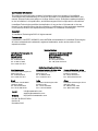
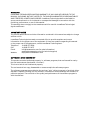
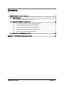
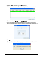
USER MANUAL
IEC61850 Communication
For LumaShield Signal Conditioners
Confidential Information
The material contained herein consists of information that is the property of LumaSense
Technologies and intended solely for use by the purchaser of the equipment described in this
manual. All specifications are subject to change without notice. Changes are made periodically
to the information in this publication, and these changes will be incorporated in new editions.
LumaSense Technologies prohibits the duplication of any portion of this manual or the use
thereof for any purpose other than the operation or maintenance of the equipment described
in this manual, without the express written permission of LumaSense Technologies.
Copyright
© LumaSense Technologies 2012. All rights reserved.
Trademarks
LumaSHIELD, LumaTEST, SoftSHIELD, and LUXTRON are trademarks of LumaSense Technologies.
All other trademarks are trademarks, registered trademarks, and/or service marks of their
respective holders.
Service Centers
LumaSense Technologies, Inc.
North America
Sales & Service
Santa Clara, CA
Ph: +1 800 631 0176
Ph: +1 408 727 1600
Fax: +1 408 727 1677
LumaSense Technologies GmbH
Other Than North America
Sales & Support
Frankfurt, Germany
Ph: +49 (0) 69 97373 0
Fax: +49 (0) 69 97373 167
Global and Regional Centers
Our Headquarter
LumaSense Technologies, Inc.
Santa Clara, CA
Ph: +1 800 631 0176
Fax: +1 408 727 1677
Americas, Australia, & Other Asia
LumaSense Technologies, Inc.
Santa Clara, CA
Ph: +1 800 631 0176
Fax: +1 408 727 1677
Europe, Middle East, Africa
LumaSense Technologies GmbH
Frankfurt, Germany
Ph: +49 (0) 69 97373 0
Fax: +49 (0) 69 97373 167
Brazil
LumaSense, Vendas Brasil
Campinas, Brasil
Ph: +55 19 3367 6533
Fax: +55 19 3367 6533
India
LumaSense Technologies, India
Mumbai, India
Ph: + 91 22 67419203
Fax: + 91 22 67419201
China
LumaSense Technologies, China
Shanghai, China
Ph: +86 133 1182 7766
Fax: +86 21 5877 2383
E-mail
Website
[email protected]
[email protected]
http://www.lumasenseinc.com
Part No 38-81101-270-EN
Revision B
December 2012
WARRANTY
LUMASENSE TECHNOLOGIES MAKES NO WARRANTY OF ANY KIND WITH REGARD TO THIS
MANUAL, INCLUDING, BUT NOT LIMITED TO, THE IMPLIED WARRANTIES OF MERCHANTABILITY
AND FITNESS FOR A PARTICULAR PURPOSE. LumaSense Technologies shall not be liable for
errors contained herein or for incidental or consequential damages in connection with the
furnishing, performance, or use of this material.
This warranty does not apply to the transducers sold for use with LumaSense Technologies’
signal conditioners.
IMPORTANT NOTICE
The product specifications and other information contained in this manual are subject to change
without notice.
LumaSense Technologies has made a concerted effort to provide complete and current
information for the proper use of the equipment. If there are questions regarding this manual
or the proper use of the equipment, contact LumaSense Technologies at:
Telephone
FAX
E-mail
Website
+1 (408) 727-1600
+1 (408) 727-1677
[email protected] (for sales information)
[email protected] (for technical support)
http://www.lumasenseinc.com
SOFTWARE LICENSE AGREEMENT
This product contains intellectual property, i.e. software programs, that are licensed for use by
the end user/customer (hereinafter “end user”).
This is not a sale of such intellectual property.
The end user shall not copy, disassemble or reverse compile the software program.
The software programs are provided to the end user “as is” without warranty of any kind, either
express or implied, including, but not limited to, warranties of merchantability and fitness for a
particular purpose. The entire risk of the quality and performance of the software program is
with the end user.
To ensure consistent document formatting, this page was intentionally left blank.
Contents
1
IEC61850 Communication Interface................................................................................. 7
1.1
IEC61850 Setup ....................................................................................................... 7
1.1.1
1.2
1.3
IEC61850 Communication Settings...................................................................... 8
Supported IEC61850 Logical Nodes ....................................................................... 10
1.2.1
Channel Temperatures Logical Node (MsrGGIO2) ............................................ 11
1.2.2
Channel Status Logical Node (ChnlStGGIO5) .................................................... 12
1.2.3
Signal Diagnostic Logical Node (DiagSiGGIO3) ................................................. 12
1.2.4
Lamp Diagnostic Logical Node (DiagLmGGIO4) ................................................ 12
1.2.5
Relay Status Logical Node (RelStGGIO1) ........................................................... 13
Set-up the LumaSHIELD and Relays ....................................................................... 13
Appendix A: Table of Available Logical Nodes .................................................................... 15
IEC61850 User Manual
Contents
v
To ensure consistent document formatting, this page was intentionally left blank.
IEC61850 User Manual
Contents
vi
1 IEC61850 Communication Interface
To address the IEC61850 Protocol, LumaSense has integrated an internal gateway into the
LumaSHIELD to perform Modbus/ IEC61850 conversion.
1.1
IEC61850 Setup
The IEC61850 communication link is established through the RJ-45 modular receptacle
(8 positions) of the LumaSHIELD signal conditioner unit.
ON / OFF Switch
Status LED’s
DB-9 receptacle for serial
connection
RJ-45 receptacle for Ethernet
(IEC61850) connection
Power-supply connector
IEC61850 User Manual
IEC61850 Communication Interface
7
The pin assignment for the Ethernet Interface is illustrated on the following figure:
Figure 1: RJ45 Pin Assignment.
Use a shielded standard Ethernet cable to connect the signal conditioner to the network.
If you plug the instrument directly into a PC, you should use an Ethernet Crossover Cable.
1.1.1
IEC61850 Communication Settings
The table below lists the LumaSHIELD communication settings to configure the Modbus link
between the LumaSHIELD and the Gateway.
Communication port
RS-485
Protocol
Modbus
Modbus ID:
107
Baud rate
9600 bps
Parity
Even
The default IP configuration of the LumaSHIELD Gateway is as follows:
IP Address:
192.168.0.121
Subnet Mask:
255.255.255.0
Gateway:
192.168.0.1
If you need to change the IP address, use the EasyConnect software provided on the
LumaSense Technologies CD (Both 32bit and 64bit supplied).
1. Launch the EasyConnect software.
2. Click on “Devices” in the left hand window.
3. Click on the “KSGL” tab in the right window and then click the selection of
“KSGLS1R1OEM” device.
IEC61850 User Manual
IEC61850 Communication Interface
8
4. Click the “Setting” menu item, then the “Scan” selection.
Make sure your device is shown. The default settings should be similar to the following:
5. Select the menu item “Settings”, then “IP Configuration”.
6. Verify that the proper device is selected (192.168.0.121) and then correct the bottom
portion of the screen with the new settings. As shown below: moved to address 10.0.7.13.
7. Press OK.
The screen will state that the IP address change requires that the module will reset. Wait
about 2 minutes for it to reset and initilization to complete.
IEC61850 User Manual
IEC61850 Communication Interface
9
To verify that the device has changed its IP address:
Use a computer that has access to the new IP address, open a DOS Command window
and ping the new IP address.
1.2
Supported IEC61850 Logical Nodes
The following examples are using the Triangle Microworks Hammer IEC-61850 Browser software
(not supplied).
Shown below is the basic structure of the IED.
This screen shot shows the temperatures of an example 4 channel system.
IEC61850 User Manual
IEC61850 Communication Interface
10
Note: In this example, only channel 1 (AnIn1 – 115.238°C) and channel 3 (AnIn3 – 37.4336°C)
have probes attached.
1.2.1
Channel Temperatures Logical Node (MsrGGIO2)
The measurements logical node contains the latest channel measure in degrees °C or °F,
depending of the configuration of the LumaSHIELD.
Data
Channel
Basic Type
MMS Tag
Channels
Temperature
reading
Channel 1
Analog Input
MsrGGIO2$MX$AnIn1$mag$f
Channel 2
Analog Input
MsrGGIO2$MX$AnIn2$mag$f
Channel 3
Analog Input
MsrGGIO2$MX$AnIn3$mag$f
Channel 4
Analog Input
MsrGGIO2$MX$AnIn4$mag$f
Channel 5
Analog Input
MsrGGIO2$MX$AnIn5$mag$f
…..
Channel 16
IEC61850 User Manual
Analog Input
MsrGGIO2$MX$AnIn16$mag$f
IEC61850 Communication Interface
11
1.2.2
Channel Status Logical Node (ChnlStGGIO5)
The Channel status logical node contains a True for each enabled channel and a False for each
disabled channel.
Data
Channel
Basic Type
MMS Tag
Channels
status
reading
Channel 1
Digital Input
ChnlStGGIO5$ST$SPCSO1$stVal
Channel 2
Digital Input
ChnlStGGIO5$ST$SPCSO2$stVal
Channel 3
Digital Input
ChnlStGGIO5$ST$SPCSO3$stVal
Channel 4
Digital Input
ChnlStGGIO5$ST$SPCSO4$stVal
Channel 5
Digital Input
ChnlStGGIO5$ST$SPCSO5$stVal
…..
Channel 16
1.2.3
Digital Input
ChnlStGGIO5$ST$SPCSO16$stVal
Signal Diagnostic Logical Node (DiagSiGGIO3)
The Signal diagnostic logical node contains the latest signal diagnostic value.
Data
Channel
Basic Type
MMS Tag
Channels
signal diag.
reading
Channel 1
Analog Input
DiagSiGGIO3$MX$AnIn1$mag$i
Channel 2
Analog Input
DiagSiGGIO3$MX$AnIn2$mag$i
Channel 3
Analog Input
DiagSiGGIO3$MX$AnIn3$mag$i
Channel 4
Analog Input
DiagSiGGIO3$MX$AnIn4$mag$i
Channel 5
Analog Input
DiagSiGGIO3$MX$AnIn5$mag$i
…..
Channel 16
1.2.4
Analog Input
DiagSiGGIO3$MX$AnIn16$mag$i
Lamp Diagnostic Logical Node (DiagLmGGIO4)
The Lamp diagnostic logical node contains the latest lamp diagnostic value.
Data
Channel
Basic Type
MMS Tag
Channels lamp
diagn reading
Channel 1
Analog Input
DiagLmGGIO4$MX$AnIn1$mag$f
Channel 2
Analog Input
DiagLmGGIO4$MX$AnIn2$mag$f
Channel 3
Analog Input
DiagLmGGIO4$MX$AnIn3$mag$f
Channel 4
Analog Input
DiagLmGGIO4$MX$AnIn4$mag$f
Channel 5
Analog Input
DiagLmGGIO4$MX$AnIn5$mag$f
…..
Channel 16
IEC61850 User Manual
Analog Input
DiagLmGGIO4$MX$AnIn6$mag$f
IEC61850 Communication Interface
12
1.2.5
Relay Status Logical Node (RelStGGIO1)
The Relay Status logical node contains a True for each enabled relay and a False for each
disabled relay.
Data
Channel
Basic Type
MMS Tag
Relay Status
reading
Relay 1
Digital Input
RelStGGIO1$ST$Ind1$stVal
Relay 2
Digital Input
RelStGGIO1$ST$Ind2$stVal
Relay 3
Digital Input
RelStGGIO1$ST$Ind3$stVal
Relay 4
Digital Input
RelStGGIO1$ST$Ind4$stVal
Relay 5
Digital Input
RelStGGIO1$ST$Ind5$stVal
Relay 6
Digital Input
RelStGGIO1$ST$Ind6$stVal
1.3
Set-up the LumaSHIELD and Relays
There are three ways to configure the LumaSHIELD and Relays:
1. Directly on the keypad of the front panel. (The LumaSHIELD may be in any protocol.)
2. Using SoftSHIELD with a serial connection to the PC (The LumaSHIELD must be in SCPI
mode.)
3. Using SCPI commands with a serial connection. (The LumaSHIELD must be in SCPI mode)
Before connecting to an IEC61850 network, your LumaSHIELD must be in Modbus Mode (See
section 1.1.1)
Consult the LumaSHIELD or SoftSHIELD Manual for programming instructions.
IEC61850 User Manual
IEC61850 Communication Interface
13
To ensure consistent document formatting, this page was intentionally left blank
IEC61850 User Manual
IEC61850 Communication Interface
14
Appendix A: Table of Available Logical Nodes
Data
Channel
Basic Type
MMS Tag
Channels measure
reading
Channel 1
Analog Input
MsrGGIO2$MX$AnIn1$mag$f
Channel 2
Analog Input
MsrGGIO2$MX$AnIn2$mag$f
Channel 3
Analog Input
MsrGGIO2$MX$AnIn3$mag$f
Channel 4
Analog Input
MsrGGIO2$MX$AnIn4$mag$f
Channel 5
Analog Input
MsrGGIO2$MX$AnIn5$mag$f
Channel 6
Analog Input
MsrGGIO2$MX$AnIn6$mag$f
Channel 1
Digital Input
ChnlStGGIO5$ST$SPCSO1$stVal
Channel 2
Digital Input
ChnlStGGIO5$ST$SPCSO2$stVal
Channel 3
Digital Input
ChnlStGGIO5$ST$SPCSO3$stVal
Channel 4
Digital Input
ChnlStGGIO5$ST$SPCSO4$stVal
Channel 5
Digital Input
ChnlStGGIO5$ST$SPCSO5$stVal
Channel 6
Digital Input
ChnlStGGIO5$ST$SPCSO6$stVal
Channel 1
Analog Input
DiagSiGGIO3$MX$AnIn1$mag$i
Channel 2
Analog Input
DiagSiGGIO3$MX$AnIn2$mag$i
Channel 3
Analog Input
DiagSiGGIO3$MX$AnIn3$mag$i
Channel 4
Analog Input
DiagSiGGIO3$MX$AnIn4$mag$i
Channel 5
Analog Input
DiagSiGGIO3$MX$AnIn5$mag$i
Channel 6
Analog Input
DiagSiGGIO3$MX$AnIn6$mag$i
Channel 1
Analog Input
DiagLmGGIO4$MX$AnIn1$mag$f
Channel 2
Analog Input
DiagLmGGIO4$MX$AnIn2$mag$f
Channel 3
Analog Input
DiagLmGGIO4$MX$AnIn3$mag$f
Channel 4
Analog Input
DiagLmGGIO4$MX$AnIn4$mag$f
Channel 5
Analog Input
DiagLmGGIO4$MX$AnIn5$mag$f
Channel 6
Analog Input
DiagLmGGIO4$MX$AnIn6$mag$f
Relay 1
Digital Input
RelStGGIO1$ST$Ind1$stVal
Relay 2
Digital Input
RelStGGIO1$ST$Ind2$stVal
Relay 3
Digital Input
RelStGGIO1$ST$Ind3$stVal
Relay 4
Digital Input
RelStGGIO1$ST$Ind4$stVal
Relay 5
Digital Input
RelStGGIO1$ST$Ind5$stVal
Relay 6
Digital Input
RelStGGIO1$ST$Ind6$stVal
Channels status
reading
Channels signal
diagnostic reading
Channels lamp
diagnostic reading
Relay Status
reading
IEC61850 User Manual
Appendix A: Table of Available Logical Nodes
15
Data
Channel
Basic Type
MMS Tag
Miscellaneous
Vendor
VisString255
LLNO$NamPlt$vendor
Software
VisString255
LLNO$NamPlt$swRev
Description
VisString255
LLNO$NamPlt$d
Release
VisString255
LLNO$NamPlt$configRev
Description
VisString255
MsrGGIO2$NamPlt$d
Description
VisString255
ChnlStGGIO5$NamPlt$d
Description
VisString255
DiagSiGGIO3$NamPlt$d
Description
VisString255
DiagLmGGIO4$NamPlt$d
Description
VisString255
RelStGGIO1$NamPlt$d
IEC61850 User Manual
Appendix A: Table of Available Logical Nodes
16