1
IPC@CHIP DK61
Getting Started IEC 618580 Basics – V.1.00
Getting Started
IPC@CHIP Embedded Web Controller Family
IEC 61850 Basics
Development Kit DK61
© 2010 Beck IPC GmbH
Page 1 of 38
IPC@CHIP DK61
Getting Started IEC 618580 Basics – V.1.00
Documentation Control
Revision:
Revision History:
1.00
1.00 – Initial release
Revision Date:
28 April 2010
Document Status:
RELEASE
© 2010 Beck IPC GmbH
Page 2 of 38
IPC@CHIP DK61
Getting Started IEC 618580 Basics – V.1.00
TABLE OF CONTENTS
1
Introduction __________________________________________________________ 4
2
Abbreviations_________________________________________________________ 5
3
System Start-up_______________________________________________________ 6
3.1
What do we need to get started? __________________________________________ 6
3.2
Steps to run the IEC 61850 Software on the Development Kit ________________ 7
3.2.1
3.2.2
3.2.3
3.2.4
3.2.5
4
5
Basics of IEC 61850 related to the Example ____________________________ 15
4.1
General remarks ________________________________________________________ 15
4.2
The main parts of the standard___________________________________________ 15
4.3
Status and ongoing work ________________________________________________ 16
4.4
Specification of signals for communication _______________________________ 16
Introduction of Example ______________________________________________ 17
5.1
General remarks and basic definitions____________________________________ 17
5.2
The DK61 Board, the Approach of IEC 61850 and the Example______________ 18
5.2.1
5.2.2
5.2.3
5.2.4
5.2.5
5.2.6
5.2.7
6
Architecture ________________________________________________________________ 18
The process interface________________________________________________________ 19
The IEC 61850 information model for general I/Os _______________________________ 19
Browsing the information of an device__________________________________________ 21
Communication services _____________________________________________________ 21
Binding of process values to standard information models ________________________ 23
System Configuration Language (SCL)_________________________________________ 25
Communication services _____________________________________________ 26
6.1.1
7
Set Up the Development Kit Hardware __________________________________________ 7
Copy the contents from the DK61 DemoCD to your PC: ___________________________ 7
Setting up the DK61 Device as Server __________________________________________ 8
Setting up the Client _________________________________________________________ 11
Building your own Server_____________________________________________________ 13
Setting up the serial communication ___________________________________________ 27
Appendix ____________________________________________________________ 28
7.1
Where to get further Information _________________________________________ 28
7.1.1
7.1.2
7.1.3
7.1.4
7.1.5
Getting Started _____________________________________________________________ 28
Updates, tools and examples _________________________________________________ 28
Support ____________________________________________________________________ 28
Order numbers _____________________________________________________________ 28
Tools related to IEC 61850 ___________________________________________________ 29
7.2
IEC 61850 Standards ____________________________________________________ 29
7.3
GetDataValues for DIPS_GGIO1.Ind3 _____________________________________ 31
7.4
Standardized Logical Nodes _____________________________________________ 32
© 2010 Beck IPC GmbH
Page 3 of 38
IPC@CHIP DK61
Getting Started IEC 618580 Basics – V.1.00
1
Introduction
Congratulations on purchasing your IPC@CHIP DK61 Development Kit. The Development Kit
is a complete ready-to-use development system for building applications based on the
Embedded Web Controllers IPC@CHIP SC123 and IPC@CHIP SC143. It runs with the
@CHIP-RTOS operating system, which includes features like a real-time kernel that is
capable of running common DOS applications concurrently, a full TCP/IP stack with a
UDP/TCP socket interface, DHCP, FTP, PPP, Telnet, Web server, APIs for CAN and USB
controllers, and IEC 61850.
The Development Kit contains both hardware and software components required for a basic
development. This document will introduce you to the basics of the standard IEC 61850 of the
DK61. Chapter 3 gets you started with creating an IEC 61850 application with your DK61.
Chapters 4 and 5 provide the basic concepts of IEC 61850 related to the DK61 with an
example.
This document is intended to provide the basic knowledge on IEC 61850 in order to run the
introductory example. The example provides basic information, communication and system
configuration information.
The use of IEC 61850 requires the software loaded onto the DK61 board. After the DK61
board has been set up it will take only a few steps to run the first example to exchange the
status values (on or off) of DIP Switches on board and to switch LEDs on and off. Basic
knowledge of communication mechanisms is a prerequisite of the following description.
Further information on IEC 61850 standards can be found in the Appendix.
© 2010 Beck IPC GmbH
Page 4 of 38
IPC@CHIP DK61
Getting Started IEC 618580 Basics – V.1.00
2
Abbreviations
IED
GOOSE
HMI
ICD
IEC
IED
INS
IP
LN
SCL
Intelligent Electronic Device
Generic Object Oriented Substation Events
Human Machine Interface
IED Capability Description
International Electro-technical Commission
Intelligent Electronic Device
Integer Status
Internet Protocol
Logical Node
System Configuration Language
© 2010 Beck IPC GmbH
Page 5 of 38
IPC@CHIP DK61
Getting Started IEC 618580 Basics – V.1.00
3
System Start-up
3.1
What do we need to get started?
-
-
The Development Kit DK61 consisting
of:
o Development Board DK60
o Embedded Web Controller
IPC@CHIP SC143 (on the
DK60)
o Serial null-modem cable
o USB cable (A-to-Mini-B)
o Ethernet patch
cable(gray)TPFF FFPT
o Ethernet crossover cable(red)
o Secure digital memory card
o Power supply unit
o Paradigm C++ Beck IPC Edition CD (including IPC@CHIPTOOL, DEBUG@CHIP
debugger,DK61 start-up documentation and drivers)
Personal Computer:
o Microsoft Windows NT/2000/XP Operating System
o Ethernet network interface
o Serial port
o USB interface
Software from the enclosed CD:
o DemoCD.html
o API User Manuals
Contains “IEC 61850 Protocol API User Manual.pdf” and
PIS10API/index.html online manual
o DK61 Client Application
o DK61 Server Application
o IEC 61850 Documents – PICS
o IEC 61850 Library
Contains all the license files for your DK61 serial number
o Presentation – Power Point Presentation: “61850 ICD Editor DK61 v3.pps”
Contains
(movies) walk through slides creating ICD Designer files and
using the DK61
o ICD Designer Demonstration Software
Be aware that the Embedded Controller SC143 and the Development
Board DK60 are electrostatic sensitive components. Observe general
precautions for handling
© 2010 Beck IPC GmbH
Page 6 of 38
IPC@CHIP DK61
Getting Started IEC 618580 Basics – V.1.00
3.2
Steps to run the IEC 61850 Software on the Development Kit
3.2.1
Set Up the Development Kit Hardware
Connect the DK61 to the power supply and your network.
3.2.2
Copy the contents from the DK61 DemoCD to your PC:
Copy the contents of the CD_DRIVE:|\*.* to C:\DK61\*.* to make all the files,
presentation, and source code examples available on your computer.
Some files need to be customized and copied to the DK61 hardware for the example
to work properly. Specifically, there is network address information on your PC and
network to be edited. Also, there is a specific ’key’ that matches your specific DK61
hardware.
The following pages describe setting this information up.
© 2010 Beck IPC GmbH
Page 7 of 38
IPC@CHIP DK61
Getting Started IEC 618580 Basics – V.1.00
3.2.3
Setting up the DK61 Device as Server
1. Open CHIPTOOL. Note your specific information for your network and DK61:
The ICD Designer User Manual is in
CD_DRIVE:\ICD Designer\ICDDesigner.pdf
and also under “Help”.
2. Open “DK61.ICD” file (copied earlier under C:\DK61\DK61 Server Application) with the ICD
Designer application. According to your specific information in CHIPTOOL:
a. Select then change the “IP”
b. Select then change the “IP-SUBNET”
c. Select then chance the “IP-GATEWAY”
© 2010 Beck IPC GmbH
Page 8 of 38
IPC@CHIP DK61
Getting Started IEC 618580 Basics – V.1.00
3. Using CHIPTOOL download the specific “PIS10.key” file matching your DK61 serial number.
From CD_Drive:\IEC 61850 Library\BECK_SSSSS, where “SSSSS” is the Serial number of
your specific DK61 (Example if Serial Number is 0583C) copy the “PIS10.key” to the DK61
4. Next, download “DK61.ICD” that you edited above with ICD Designer and also the
SV61850.EXE to your DK61.
5. Again using CHIPTOOL, right-click on your DK61 and open a Telnet session into the DK61
© 2010 Beck IPC GmbH
Page 9 of 38
IPC@CHIP DK61
Getting Started IEC 618580 Basics – V.1.00
6. Start the server by typing “SV61850 DK61.ICD” at command prompt in Telnet.
If there are any errors, please refer to API User Manual to resolve it.
7. Start IEDScout or any other Client test application to see if you can connect to the 61850
Server on DK61
8. On successful connection, autoexec.bat can be downloaded so that server starts
automatically on reboot of DK61.
© 2010 Beck IPC GmbH
Page 10 of 38
IPC@CHIP DK61
Getting Started IEC 618580 Basics – V.1.00
3.2.4
Setting up the Client
1. On the PC that you will use as the client type at the Command Prompt: “ipconfig /all”
2. Note the information
from “ipconfig /all”
then enter that
information into ICD
Designer.
NOTE: This shows the
“DK61 Client.ICD” file. Do
NOT confuse this with the
Server “DK61.ICD” file
The ICD Designer User Manual is available on
CD_DRIVE:\ICD Designer\ICDDesigner.pdf
and also under “Help”.
3. Run the DK61Demo.exe IEC 61850 Client
application:
C:\DK61\DK61 Client Application\DK61Demo.exe
4. Operate Dip switch and Led Output and
notice the appropriate changes in the
Client application
© 2010 Beck IPC GmbH
Page 11 of 38
IPC@CHIP DK61
Getting Started IEC 618580 Basics – V.1.00
DK61Demo.exe:
© 2010 Beck IPC GmbH
Page 12 of 38
IPC@CHIP DK61
Getting Started IEC 618580 Basics – V.1.00
3.2.5
Building your own Server
1. Copy to PC iec61850.lib and IEC61850API.h From CD_Drive:\IEC 61850
Library\BECK_SSSSS; where SSSSS is the Serial number of your DK61 (Example : If the Serial
number is A07899)
2. Open paradigm , Create New Project and than Select Add Node
© 2010 Beck IPC GmbH
Page 13 of 38
IPC@CHIP DK61
Getting Started IEC 618580 Basics – V.1.00
3. Add nodes iec61850.lib and iec61850Api.h
4. Add your server application source code to the project (sample available at CD_Drive:\ DK61
Server Application\Sample Source Code) .
5. Build your custom Server executable.
6. Download your executable to the DK61.
© 2010 Beck IPC GmbH
Page 14 of 38
IPC@CHIP DK61
Getting Started IEC 618580 Basics – V.1.00
4
Basics of IEC 61850 related to the Example
4.1
General remarks
The standard series IEC 61850 provides a uniform framework for the specification, exchange
and configuration of information. It applies to the Process level (actuators, sensors of any
type), level of Control and Protection and higher levels as Station level, e.g., in substations
(HMI and remote control link).
The standard comprises:
1. General rules (project management, environmental and EMC requirements, etc.)
2. Common and domain specific information for functions and devices (measured values,
status and switching information, etc.),
3. Information of and about primary devices (switches, transformers and instrument
transformers) and
4. Information exchange for protection, monitoring, control, measurement and metering
5. A configuration language.
Interoperability between devices and between engineering (configuration) tools is the main
goal of IEC 61850. It is intended to enable two or more IEDs (Intelligent Electronic Devices)
from one or more suppliers to exchange information which is defined in the IEC 61850
standard and to unambiguously interpret and use the information in order to implement the
functionality required by the application.
4.2
The main parts of the standard
The standard covers general requirements relating to substations, engineering, data models,
communications solutions and conformity testing. The original scope (substations) has been
extended to power utility automation. It may be used in any application domain with similar
requirements.
The first 16 parts of the standard series have been issued as official IEC standards. It is a
toolkit that can be used to design open automation systems. In addition to describing the
information flow between functions of automation devices, IEC 61850 provides
communications mechanisms between the functions. It leaves a significant amount of freedom
to implement communications, so that manufacturers can adapt their functions and system
platform to a variety of markets and user requirements.
Parts 1 to 4 contain the introduction and all of the general requirements.
Part 5 describes the basic requirements for substation automation functions.
The substation configuration language is defined in Part 6.
Based on Part 5, Parts 7-1, 7-2, 7 3 ,7-4, 7410, 7-420, and IEC 61400-25-2 contain
communication definitions for a variety of functions (data models and communications
services).
Parts 8 and 9 define mappings of the definitions contained in Part 7 to real communications
networks.
Part 10 defines the basics for conformance tests.
IEC 61850 standards are found in the Appendix 7.2 - IEC 61850 Standards.
© 2010 Beck IPC GmbH
Page 15 of 38
IPC@CHIP DK61
Getting Started IEC 618580 Basics – V.1.00
4.3
Status and ongoing work
While the last sections of IEC 61850 were being published, work was already in progress on
inclusion of applications outside of substations. Many of the world’s major power utilities and
manufacturers of automation systems are involved in the work to enhance the standards. All of
the major manufacturers for electric power systems offer conforming products or are in the
process of developing them. Widespread use of IEC 61850 has begun in 2007. The
introduction of IEC 61850 compliant products and widespread use are now well underway.
The parties who are involved in implementation and use of the standard now have the task of
using the experience that they have gained with IEC 61850 to contribute to the ongoing work
at IEC TC 57. Many international companies (users and manufacturers) are members of the
UCA International Users Group. This organization supports the introduction of IEC 61850 and
continued development of the standard (www.ucaiug.org).
4.4
Specification of signals for communication
It was common practice in the past to specify signals in long lists which were drawn up for a
particular manufacturer, user or project. IEC 61850 takes a different approach. The standard
uses a designator (readable text), a data type (such as double point) and other descriptive
information to define the signals. The data models are independent of the communication
services which are used to access actual data values or the models themselves. The data
models represent the information which can be exchanged with a device. They essentially
describe the device interface. Data models provide new ways of interacting with intelligent
devices. IEC 61850 defines the following four key aspects which are independent of each
other and which build on one other:
Standardized information: for circuit breakers: units, measured values, control, metadata,
etc. including a self-description (IEC 61850- 7-4); standardized information is based on a
general set of about 20 common data types (status, measured value, metering data (IEC
61850-7-3); some standardized information is specific to substations, and other information is
more general. The definition of new information models, which reuse standardized information,
is expressly supported.
Standardized services: for simple data access, reporting logging, querying, device control,
etc. (IEC 61850-7-2). The standardized services can be used with standardized information (in
61850-7-4) or with any new or extended information models.
Standardized networks: suitable networks are selected for exchanging messages in the strict
sense of the term. Standardized communication systems are used for the standardized
services, standardized information and any other type of information (IEC 61850-8-1 and -9-2).
Standardized configuration: A complete, formal description is generated for the devices and
the entire system. IEC 61850-6 defines an XML-based system description language
(Substation Configuration Language, SCL), which is used to generate configuration files.
© 2010 Beck IPC GmbH
Page 16 of 38
IPC@CHIP DK61
Getting Started IEC 618580 Basics – V.1.00
5
Introduction of Example
5.1
General remarks and basic definitions
The following example focuses on the signals to be described and exchanged with IEC 61850.
IEC 61850 provides signal designations (names) for application information produced,
exchanged and consumed by devices.
The communication services provide the exchange of values in real-time (GOOSE and
Sampled Values, based on Layer 2 Multicast) and in a client-server relation based on TCP/IP
and higher layer protocols.
The configuration language SCL describes all information of a system and the flow of the
information between the devices of the system.
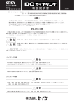
These basic features of IEC 61850 are depicted in the following figure:
Device E
Device D
Device C
Device A
Device B
Get…
Operate „Open“
TCP/IP based
Report „Open“
(event)
Log „Open“
Log
Query Log
Layer 2
Multicast
listen to …
GOOSE „Trip“
(event)
SMV „Samples“
(cyclic)
request/listen to …
information, send to …
System Configuration Language (SCL) – XML document
Device B provides information (Status, 3-phase electrical Measurements, sensor information,
Engineering and Configuration information, Nameplates, etc.) that can be retrieved (Get) by
Device B. Device A may operate something in Device B (open a breaker, start a program, etc.)
A change of the breaker position may cause a report of the new value to a specific Device; or
the change may be logged and queried for retrieval later on. These services use a clientserver communication based on TCP/IP.
IEC 61850 provides two special services for real-time communication based on Layer 2
multicast services (on publisher – to – many subscribers). GOOSE allows the exchange of any
information in short reaction times (less 5 ms). Sample Measured Values (SMV) are
intended to exchange values cyclically in a high frequency (typical sample rate: 4.000
messages per second for special functions).
© 2010 Beck IPC GmbH
Page 17 of 38
IPC@CHIP DK61
Getting Started IEC 618580 Basics – V.1.00
The System Configuration Language (SCL) describes the sources of the information, which
services are to be used, who should listen to the information exchanged (information flow).
Devices A, C, D and E are configured to listen to the red Multicast message sent by Device B.
Devices could implement one or more of the following roles: Client, Server, Publisher, or
Subscriber.
The version of the IEC 61850 in the DK61 for this description is V1.0. This version provides
the roles Server, Publisher (GOOSE) and Subscriber (GOOSE).
The example introduces a Server that allows the access of information from DIP Switches and
information for LEDs. The application between IEC 61850 and the Digital I/Os is implemented
in “C”.
5.2
The DK61 Board, the Approach of IEC 61850 and the Example
5.2.1
Architecture
The crucial aspects shown in the following figure (related to the example in this document)
are:
1. The Ethernet connectivity on the top; the devices (the DK61 and two other documents
shown to the left) are understood to be connected to one subnet.
2. The Digital Inputs and Outputs shown at the bottom.
3. The Inputs are implemented as 8 DIP Switches and the Output signals are implemented as
8 LEDs. The position of the DIP Switches can manually be changed. The positions
(information) are intended to be communicated by IEC 61850 services. The LEDs will be
used to demonstrate the control services.
4. The physical Inputs and Outputs are connected to an application.
5. For the purpose of communication it is required to designate (name) and format the
information to be exchanged (in the first example position inputs and control outputs).
Ethernet
IEC 61850 Server/
Publisher
Information
Information
Model
Model
Application
Application
HMI/Application
HMI/Application
IEC 61850 Client/
Subscriber
© 2010 Beck IPC GmbH
…
Client/Server
on TCP/IP
GOOSE
Sampled Values
Ethernet
…
GOOSE
GOOSEValues
Sampled
Sampled
Values
Client/Server
on TCP/IP
Client/Server
on TCP/IP
…
Ethernet
Ethernet
Information
Model
Application
Input/Output
Digital Input/Output
Page 18 of 38
IPC@CHIP DK61
Getting Started IEC 618580 Basics – V.1.00
5.2.2
The process interface
The Digital Inputs and Outputs are shown in the following picture. The DIP Switches are
shown on the left. The switches are identified as “DIP Input 1” to “DIP Input 8”. The LEDs are
“LED Output 1” to “LED Output 8”. These names are defined and used in this description: the
names in the corresponding C application are:
/* Object Types */
enum
{
DIGITAL_INPUT
= 1,
DIGITAL_OUTPUT = 2,
}eObjectTypes;
// Digital Input (DIP Switch )
// Digital Output (LED )
The access to the DIP Switches or LEDs from a client requires the access (path) information
to identify (address) the right DIP Switch. The Application program may use any name for the
DIP Switches. The programmer is free to choose any name. This name usually is not
recommended to be used by a client – because it may be changed by the programmer at any
time.
DIP Input 1
LED Output 1
LED Output 8
DIP Input 8
5.2.3
The IEC 61850 information model for general I/Os
IEC 61850 provides standardized designations for this kind of information. The so-called
standardized Logical Node (LN) “GGIO” (Generic Process Input Output) is used to designate
input and output signals.
The following excerpt of the LN GGIO depicts three kinds of information (each having a Data
Object (DO)):
Measured Values (AnIn), Controls (SPCSO) and Status Information (Ind).
Each has a Data Object has a suffix of “1” (e.g., Ind1) indicating that a LN GGIO may have
four Data Objects (Ind1, Ind2, Ind4, and Ind4). These four Data Objects will represent the
upper four of the eight DIP Switches in the example.
© 2010 Beck IPC GmbH
Page 19 of 38
IPC@CHIP DK61
Getting Started IEC 618580 Basics – V.1.00
GGIO class
Measured Values
AnIn1
instMag
q
t
units
Controls
SPCSO1
ctlVal
stVal
q
t
Status information
Ind1
stVal
q
t
stVal
q
t
IntIn1
AnalogueValue
Quality
TimeStamp
Unit
Analogue input
BOOLEAN
BOOLEAN
Quality
TimeStamp
Single point
controllable status
output
BOOLEAN
Quality
TimeStamp
General indication
(binary input)
INT32
Quality
TimeStamp
Integer status input
The eight LEDs are represented by eight Data Objects SPCSO1 … SPCSO8.
The signal designations (names) for both are shown in the next figure.
IEC 61850
Standard Names (in blue)
IEC 61850
Standard Names (in blue)
DIPS_GGIO1.Ind1.stVal
.Ind2.stVal
.Ind3.stVal
.Ind4.stVal
LEDO_GGIO3.SPCSO1.ctlVal
.SPCSO2.ctlVal
.SPCSO3.ctlVal
.SPCSO4.ctlVal
.SPCSO5.ctlVal
.SPCSO6.ctlVal
.SPCSO7.ctlVal
.SPCSO8.ctlVal
DIP Switches
General indication
(binary input)
LED Output
Single Point Controllable
Status Output
The blue parts of the names are defined in the standard. The Logical Node GGIO has been
extended by a prefix to relate the Logical Node to the DIP Switches respectively to the LEDs.
Each Logical Node has also an instance number (1 and 3) – to differentiate several Logical
Nodes that have the same class name.
© 2010 Beck IPC GmbH
Page 20 of 38
IPC@CHIP DK61
Getting Started IEC 618580 Basics – V.1.00
5.2.4
Browsing the information of an device
A browser (IED Scout) depicts the information accordingly. The Logical Node DIPS_GGIO1
has Status Information (designated with the “FC=ST”). Besides common information Mod,
Beh, Health, the Logical Node has a Data Object Ind1 with three Data Attributes: stVal, q,
and t.
The browser has services to read the value of Ind1 one or cyclically (Polling). To read the
value of the DIPS_GGIO1.ST.Ind1.stVal requires to send this name to the DK61 using the
appropriate IEC 61850 service (GetDataObjectValues).
5.2.5
Communication services
The next figure shows the communication for getting the value of the third DIP Switch.
HMI
IEC 61850
Standard Service
GetDataVa
lues
DIPS_GGIO
1.Ind3.stVal
Value T/F
IEC 61850
Standard Names (in blue)
DIPS_GGIO1.Ind1.stVal
.Ind2.stVal
.Ind3.stVal
.Ind4.stVal
The message received by the DK61 has to be interpreted by the IEC 61850 software to figure
out which DIP Switch is addressed to return the right value. The arrows shown in the above
figure are pointing to the hardware DIP Switches. These “arrows” need to be specified in a
way that allows the software to address internally the right internal signal of the DIP Switch.
The following figures show the relation between the physical I/Os, the internal memory and the
name used in the communication. The following figure maps the physical I/Os to a list of inputs
(1-8) and outputs (1-8). This list represents the memory location in which values may be
stored.
© 2010 Beck IPC GmbH
Page 21 of 38
IPC@CHIP DK61
Getting Started IEC 618580 Basics – V.1.00
Application
Program
Interface
Memory
DIP Input 1
Input 1
Input 2
Input 3
Input 4
Input 5
Input 6
Input 7
Input 8
Output 1
Output 2
Output 3
Output 4
Output 5
Output 6
Output 7
Output 8
LED Output 1
LED Output 8
DIP Input 8
The communication stack of the IEC 61850 server (as shown in the following figure) is in
principle accessing the memory location. These names “Input 1” to “Output 8” do not provide
and specific meaning. To do so, there is a need of a mapping of the local information (e.g.,
value of DIP Switch position, time stamp of last change and quality of value (good or bad)) to
the standardized designation.
Application
Program
Interface
IEC 61850
Stack (S)
Input 1
Input 2
Input 3
Input 4
Input 5
Input 6
Input 7
Input 8
Read
Value T/F
Output 1
Output 2
Output 3
Output 4
Output 5
Output 6
Output 7
Output 8
The Memory table with eight Inputs and eight Outputs is shown at the right side of the
following picture. The relation between these “locations” and the access information of the
standardized signal names need to be specified.
The Data Object DIPS_GGIO1.ST.Ind1 of the corresponding Logical Node specifies three
Data Attributes:
Ind1
stVal
q
t
BOOLEAN
Quality
TimeStamp
Each of the three attributes will be communicated when a client reads the Data Object Ind1.
The value stVal represents the status of a DIP Switch. The information, if it refers to the first,
second, or the eights is specified by the name DIPS_GGIO1.ST.Ind1.stVal. The other two
attributes q and t are also required to be specified – and they need also be stored together
with the status value.
© 2010 Beck IPC GmbH
Page 22 of 38
IPC@CHIP DK61
Getting Started IEC 618580 Basics – V.1.00
5.2.6
Binding of process values to standard information models
The binding of the memory to the access specific information is shown in the following figure.
When the communication stack receives a GetDataValues request for the Data Object
DIPS_GGIO1.ST.Ind1, then needs to get the corresponding reference to the memory
locations for the stVal, q and t.
The API used for the first example uses a hierarchy of three fields: Field1 selects the position
in the corresponding list between 1 and 8; Field2 (to identify if the value is related to the DIPs
or to the LEDs; Field3 references to the values for stVal, q and t. This mapping is unique in
order to refer to the correct memory location for any of the values.
The communication stack uses this hierarchical reference to get the value from the
application. The following figure shows how the service <GetDataValues for
DIPS_GGIO1.Ind3.stVal> is mapped the corresponding memory location (that is bound to
the real DIP Switch 3).
The stack uses the local Read (at the API between the communication software and the real
application) with the three fields: Field1=3 (means third DIP Switch), Field2=1 (means DIP
Switches), and Field3=1 (means Value).
The returned value needs to be encoded according to the type of the Logical Node GGIO and
Ind1.stVal. The type is a BOOLEAN. The Value TRUE or FALSE will be returned to the
client that issued the GetDataValues request.
© 2010 Beck IPC GmbH
Page 23 of 38
IPC@CHIP DK61
Getting Started IEC 618580 Basics – V.1.00
The IEC 61850 communication stack is part of an entity between the messages on the
communication link (TCP/IP, Ethernet, …) and the local Application.
The concrete encoding of the request and response messages for the service
<GetDataValues for DIPS_GGIO1.Ind3> is shown in the Appendix 7.3 - GetDataValues for
DIPS_GGIO1.Ind3.
The mapping table in this example is defined by the system designer of the API between the
IEC 61850 communication stack and the real application. It is up to the system designer how
to organize the internal communication between the stack and the application. From a
communication point of view it is not visible during the exchange of messages with that
particular server device. As shown in the next figure, the client just needs to know the name of
the Data Object DIPS_GGIO1.Ind3.Ind3. The name is “translated” into an internal access
mechanism using a table to map between the standard name and the memory location of the
value.
© 2010 Beck IPC GmbH
Page 24 of 38
IPC@CHIP DK61
Getting Started IEC 618580 Basics – V.1.00
The communication stack may have its own memory that holds a copy of the real value from
the application. The copy could be updated cyclically, on request by the communication stack,
or by an event from the application. The service <GetDataValues for DIPS_GGIO1.Ind3>
does not care about the implementation of the API. The difference between the three update
mechanisms is not visible in the standard communication – except that the delay is longer or
shorter depending on the mechanism used.
The timestamp and the quality information associated with the data value are provided the
same way as the process value.
5.2.7
System Configuration Language (SCL)
The configuration of the information model and the binding of the model to the real values are
described by the System Configuration Language (SCL). The following figure shows the
formal syntax of the binding based on the three Fields: Field1 (position), Field2 (DIP or LED),
and Field3 (value, quality or timestamp).
© 2010 Beck IPC GmbH
Page 25 of 38
IPC@CHIP DK61
Getting Started IEC 618580 Basics – V.1.00
6
Communication services
IEC 61850 Client
IEC 61850
Stack (C)
IEC 61850 Server
Report
GOOSE
Value T/F
IEC 61850
Stack (S)
nge
Value cha
alues
Sampled V
Value T/F
Event
© 2010 Beck IPC GmbH
Event
Event
Page 26 of 38
IPC@CHIP DK61
Getting Started IEC 618580 Basics – V.1.00
6.1.1
Setting up the serial communication
To set up serial communication to your Development Kit DK61 you need the enclosed nullmodem cable.
1. Connect the null-modem cable to a free serial port of your PC and with the COM1
interface of the DK61.
2. Choose Tools → Terminal from the IPC@CHIPTOOL main menu
3. In the connection dialog that now opens choose the following settings:
o Connection Type: Serial
o Port: The serial port of your PC that you connected the null-modem cable to, e.g.
COM1
o Baudrate: 19200
© 2010 Beck IPC GmbH
Page 27 of 38
IPC@CHIP DK61
Getting Started IEC 618580 Basics – V.1.00
7
Appendix
7.1
Where to get further Information
7.1.1
Getting Started
All software referred to in this document can be downloaded from out Getting Started website
at http://www.beck-ipc.com/gettingstarted.
7.1.2
Updates, tools and examples
Regularly check out IPC@CHIP website at http://www.beck-ipc.com/ipc for:
@CHIP RTOS updates
New APIs
Example programs that you may use as a base for your own applications
Useful tools for your development
Application notes
7.1.3
Support
If you need support please…
1. Check our support website at http://www.beck-ipc.com/ipc/support including a FAQ.
2. Visit our newsgroup at http://www.beck-ipc.com/ipc/support/forum. Here you will find a lot
of answers to customer problems and you can also add your own ideas and questions.
3. Contact our support at [email protected]. Of course you may also contact us by
phone. But please use email if possible. This not only reduces the time you spend on the
phone, it also allows us to easily manage the questions and identify problem areas.
Important or frequent questions and the corresponding answers are becoming part of our
FAQ that is published on the Internet.
7.1.4
Order numbers
Most parts of the Development Kit DK61 can be ordered separately. Please visit our online
shop. These are the order numbers.
DK61 Development Kit
DK60 Development Board
ZK14 serial null-modem cable
PSE10 power supply
Paradigm C++ Beck Edition
© 2010 Beck IPC GmbH
542750
542751
195837
538934
541522
Page 28 of 38
IPC@CHIP DK61
Getting Started IEC 618580 Basics – V.1.00
7.1.5
Tools related to IEC 61850
The following tools may be used for the communication between an IEC 61850 server and
client:
IED Scout – IEC 61850 Browser; Download demo version:
http://www.omicron.at/en/products/pro/communication-protocols/iec-61850/iedscoutv210/
Wireshark – IEC 61850 Network Analyser; Download open source version:
http://sourceforge.net/projects/wireshark/
UNICA Network Analyser; Download of demo version:
http://www.nettedautomation.com/solutions/uca/products/netana/index.html
7.2
IEC 61850 Standards
IEC 61850-1
Introduction and Overview
Introduction and overview of all of the parts of IEC 61850
IEC 61850-2
Glossary
Terminology
IEC 61850-3
General Requirements
Quality requirements (reliability, maintainability, system availability, portability, IT security), operating
conditions, auxiliary services and other engineering standards
IEC 61850-4
System and Project Management
Engineering services requirements (parameter classification, engineering tools, documentation),
system Basics usage cycle (product versions, factory setup, support after factory setup), quality
assurance (responsibilities, test systems, type tests, system tests, factory acceptance tests (FAT) and
site acceptance tests (SAT)
IEC 61850-5
Communications Requirements for Functions and Device Models
The logical nodes principle, logical communications links, items of information for communications
(PICOM), logical nodes and associated PICOMs, functions, performance requirements (response
times, etc.), dynamic scenarios (information flow requirements under various operating conditions)
IEC 61850-6
Configuration Description Language for Communication
Communication in Electrical Substations Formal description of the single-line schemas, devices,
system structure and how they fit into the single-line schema
IEC 61850-7-1
Basic Communication Structure for Substation and Feeder Equipment
Introduction to IEC 61850-7-x, communications principles and models
IEC 61850-7-2
© 2010 Beck IPC GmbH
Page 29 of 38
IPC@CHIP DK61
Getting Started IEC 618580 Basics – V.1.00
Basic Communication Structure for Substation and Feeder Equipment – Abstract Communication
Service Interface (ACSI)Description of the Abstract Communication Service Interface (ACSI),
specification of the Abstract Communication Service Interface, server database model
IEC 61850-7-3
Basic Communication Structure for Substation and Feeder Equipment – Common Data Classes
Common data classes and attribute definitions
IEC 61850-7-4
Basic Communication Structure for Substation and Feeder Equipment
Definition von compatible logical node classes and data classes and their logical addressing. General
and typical station abstract classes for logical nodes and data
IEC 61850-7-410
Hydroelectric power plants - Communication for monitoring and control
Extension of Information models for Hydro Power Plants.
IEC 61850-7-420
Communications systems for distributed energy resources (DER) - Logical nodes
Extension of Information models for decentralized Energy resources like PV, Fuel Cells, Solar, etc.
IEC 61400-25-2
Communications for monitoring and control of wind power plants
Extension of Information models for Wind Power Plants.
IEC 61850-8-1
Specific Communication Service Mapping (SCSM) – Mappings to MMS
(ISO/IEC 9506- Part 1 and Part 2) and to ISO/IEC 8802-3
Communication mapping in the entire station (client-server communication for SCADA functions and
GOOSE and GSSE data exchange for real time requirements, for example for tripping signals
IEC 61850-9-2
Specific Communication Service Mapping (SCSM) – Sample Values over ISO/IEC 8802-3
Mapping for bus-type, flexible communication of sample values from instrument transformers (with
and without Merging Unit)
IEC 61850-10
Conformance Testing
Basic Conformance testing methods
© 2010 Beck IPC GmbH
Page 30 of 38
IPC@CHIP DK61
Getting Started IEC 618580 Basics – V.1.00
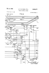
7.3
GetDataValues for DIPS_GGIO1.Ind3
The following figures show the request and response messages of the service <GetDataValues for
DIPS_GGIO1.Ind3>. This message comprises all layers from Data Link (Ethernet), over IP, TCP,
upper layers including MMS.
The IEC 61850-7-2 service <GetDataValues for DIPS_GGIO1.Ind3> is mapped to a MMS Read
Request message. The Item Name at the bottom (ItemName) is “DIPS_GGIO1$ST$nd3”. The $ is
used as the MMS-Separator (instead of a “.”). The “ST” is indicating the status information (stVal, q
and t). The DomainName is used to carry the Logical Device Name of the IEC 61850. The Logical
Device is (as for now) a container that contains Logical Nodes.
Read Request:
The MMS response message contains a Structure of three components with the value and the
corresponding Type. The first value is of type BOOLEAN (it represents the stVal). The second type is
a Bitstring (that represents the quality information). The last component is the UTC time stamp – note
that the time of the clock was not synchronized during the test.
© 2010 Beck IPC GmbH
Page 31 of 38
IPC@CHIP DK61
Getting Started IEC 618580 Basics – V.1.00
7.4
Standardized Logical Nodes
LN Group
L
System LNs
A
Automatic
Control
C
Control
#
1
2
3
4
Clause
5.3.2
5.3.3
5.3.4
5.3.5
5
6
7
8
9
10
11
12
13
14
15
16
17
18
19
20
21
5.3.6
5.3.7
5.3.8
5.3.9
5.3.10
5.4.2
5.4.3
5.4.4
5.4.5
5.4.6
5.5.2
5.5.3
5.5.4
5.5.5
5.5.6
5.5.7
5.2.2
D
Decentralized
Energy
22
Resources
23
5.2.3
5.2.4
24
25
26
27
5.2.5
5.2.6
5.2.7
5.2.8
28
5.2.9
29
30
31
32
33
34
35
36
37
38
39
40
41
42
43
5.3.2
5.3.3
5.3.4
6.1.2
6.1.3
6.1.4
6.1.5
6.2.2
6.2.3
6.3.2
7.1.3
7.2.3
7.2.4
7.2.5
7.3.3
© 2010 Beck IPC GmbH
Description
Physical device information
Common Logical Node
Logical node zero
Physical Communication channel
Supervision
GOOSE subscription
Sampled value subscription
Time management
Time master supervision
Service tracking
Neutral current regulator
Reactive power control
Resistor control
Automatic tap changer controller
Voltage control
Alarm handling
Cooling group control
Interlocking
Point-on-wave switching
Switch controller
Synchronizer controller
DER plant corporate characteristics
at the ECP
Operational characteristics at ECP
DER operational authority at the
ECP
Operating mode at ECP
Status information at the ECP
DER economic dispatch parameters
DER energy and/or ancillary
services schedule control
DER energy and/or ancillary
services schedule
DER controller characteristics
DER controller status
DER supervisory control
DER unit generator
DER generator ratings
DER advanced generator ratings
Generator cost
Excitation ratings
Excitation
Speed/Frequency Controller
Reciprocating Engine
Fuel cell controller
Fuel cell stack
Fuel processing module
Photovoltaics module ratings
Name
LPHD
Common LN
LLN0
LCCH
Document
7-4 Ed2 FDIS
7-4 Ed2 FDIS
7-4 Ed2 FDIS
7-4 Ed2 FDIS
LGOS
LSVS
LTIM
LTMS
LTRK
ANCR
ARCO
ARIS
ATCC
AVCO
CALH
CCGR
CILO
CPOW
CSWI
CSYN
DCRP
7-4 Ed2 FDIS
7-4 Ed2 FDIS
7-4 Ed2 FDIS
7-4 Ed2 FDIS
7-4 Ed2 FDIS
7-4 Ed2 FDIS
7-4 Ed2 FDIS
7-4 Ed2 FDIS
7-4 Ed2 FDIS
7-4 Ed2 FDIS
7-4 Ed2 FDIS
7-4 Ed2 FDIS
7-4 Ed2 FDIS
7-4 Ed2 FDIS
7-4 Ed2 FDIS
7-4 Ed2 FDIS
7-420 Ed1 IS
DOPR
DOPA
7-420 Ed1 IS
7-420 Ed1 IS
DOPM
DPST
DCCT
DSCC
7-420
7-420
7-420
7-420
DSCH
7-420 Ed1 IS
DRCT
DRCS
DRCC
DGEN
DRAT
DRAZ
DCST
DREX
DEXC
DSFC
DCIP
DFCL
DSTK
DFPM
DPVM
7-420
7-420
7-420
7-420
7-420
7-420
7-420
7-420
7-420
7-420
7-420
7-420
7-420
7-420
7-420
Ed1
Ed1
Ed1
Ed1
Ed1
Ed1
Ed1
Ed1
Ed1
Ed1
Ed1
Ed1
Ed1
Ed1
Ed1
Ed1
Ed1
Ed1
Ed1
IS
IS
IS
IS
IS
IS
IS
IS
IS
IS
IS
IS
IS
IS
IS
IS
IS
IS
IS
Page 32 of 38
IPC@CHIP DK61
Getting Started IEC 618580 Basics – V.1.00
LN Group
F
Functional
Blocks
G
Generic
H
Hydro Power
#
44
45
46
47
48
49
50
51
52
53
54
55
56
57
58
59
60
61
62
63
64
65
66
67
68
69
70
71
72
73
74
75
76
77
78
79
80
81
82
83
84
85
86
87
88
89
90
91
92
93
© 2010 Beck IPC GmbH
Clause
7.3.4
7.3.5
7.3.6
7.4.3
7.4.4
7.4.5
7.1.3
7.2.3
8.1.3
5.6.2
5.6.3
5.6.4
5.6.5
5.6.6
5.6.7
5.6.8
5.6.9
5.6.10
7.2.2
7.2.3
7.2.4
7.2.5
7.2.6
7.2.7
7.2.8
7.2.9
7.2.10
8.4.2
5.7.2
5.7.3
5.7.4
5.7.5
7.3.2
7.3.3.
7.3.4
7.3.5
7.3.6
7.3.7
7.3.8
7.3.9
7.3.10
7.3.11
7.3.12
7.3.13
7.3.14
7.3.15
7.3.16
7.3.17
7.3.18
7.3.19
Description
Photovoltaics array characteristics
Photovoltaics array controller
Tracking controller
CHP system controller
Thermal storage
Boiler
Reciprocating Engine
Fuel cell controller
Fuel delivery system
Counter
Curve shape description
Generic Filter
Control function output limitation
PID regulator
Ramp function
Set-point control function
Action at over threshold
Action at under threshold
Counter
Curve shape description
Generic Filter
Control function output limitation
PID regulator
Ramp function
Set-point control function
Action at over threshold
Action at under threshold
Sequencer
Generic automatic process control
Generic process I/O
Generic log
Generic security application
Turbine - generator shaft bearing
Combinator
Hydropower dam
Dam leakage supervision
Gate position indicator
Dam gate
Intake gate
Joint control
Leakage supervision
Water level indicator
Mechanical brake
Needle control
Water net head data
Dam over-topping protection
Hydropower / water reservoir
Hydropower unit sequencer
Speed monitoring
Hydropower unit
Name
DPVA
DPVC
DTRC
DCHC
DCTS
DCHB
DCIP
DFCL
DFLV
FCNT
FCSD
FFIL
FLIM
FPID
FRMP
FSPT
FXOT
FXUT
FCNT
FCSD
FFIL
FLIM
FPID
FRMP
FSPT
FXOT
FXUT
FSEQ
GAPC
GGIO
GLOG
GSAL
HBRG
HCOM
HDAM
HDLS
HGPI
HGTE
HITG
HJCL
HLKG
HLVL
HMBR
HNDL
HNHD
HOTP
HRES
HSEQ
HSPD
HUNT
Document
7-420 Ed1 IS
7-420 Ed1 IS
7-420 Ed1 IS
7-420 Ed1 IS
7-420 Ed1 IS
7-420 Ed1 IS
7-420 Ed1 IS
7-420 Ed1 IS
7-420 Ed1 IS
7-4 Ed2 FDIS
7-4 Ed2 FDIS
7-4 Ed2 FDIS
7-4 Ed2 FDIS
7-4 Ed2 FDIS
7-4 Ed2 FDIS
7-4 Ed2 FDIS
7-4 Ed2 FDIS
7-4 Ed2 FDIS
7-410 Ed1 IS
7-410 Ed1 IS
7-410 Ed1 IS
7-410 Ed1 IS
7-410 Ed1 IS
7-410 Ed1 IS
7-410 Ed1 IS
7-410 Ed1 IS
7-410 Ed1 IS
7-420 Ed1 IS
7-4 Ed2 FDIS
7-4 Ed2 FDIS
7-4 Ed2 FDIS
7-4 Ed2 FDIS
7-410 Ed1 IS
7-410 Ed1 IS
7-410 Ed1 IS
7-410 Ed1 IS
7-410 Ed1 IS
7-410 Ed1 IS
7-410 Ed1 IS
7-410 Ed1 IS
7-410 Ed1 IS
7-410 Ed1 IS
7-410 Ed1 IS
7-410 Ed1 IS
7-410 Ed1 IS
7-410 Ed1 IS
7-410 Ed1 IS
7-410 Ed1 IS
7-410 Ed1 IS
7-410 Ed1 IS
Page 33 of 38
IPC@CHIP DK61
Getting Started IEC 618580 Basics – V.1.00
LN Group
#
94
95
96
97
I
98
Interfacing
99
and Archiving
100
K
Mechanical
and nonelectric
primary
equipment
101
102
103
104
105
106
107
108
109
110
111
112
113
114
115
116
117
118
119
120
121
M
Metering and 122
measurement 123
124
125
126
127
128
129
130
131
132
133
P
134
Protection
135
functions
136
137
138
139
140
141
© 2010 Beck IPC GmbH
Clause
7.3.20
5.8.2
5.8.3
5.8.4
5.8.5
5.8.6
5.8.7
7.4.2
5.9.2
5.9.3
5.9.4
5.9.5
5.9.6
7.5.2
7.5.3
7.5.4
7.5.5
7.5.6
5.10.2
5.10.3
5.10.4
5.10.5
5.10.6
5.10.7
5.10.8
5.10.9
5.10.10
5.10.11
5.10.12
5.10.13
5.10.14
7.6.2
7.6.3
7.6.4
7.6.5
8.1.2
8.5.3
8.5.4
8.5.5
8.5.7
5.11.2
5.11.3
5.11.4
5.11.5
5.11.6
5.11.7
5.11.8
5.11.9
Description
Water control
Archiving
Human machine interface
Safety alarm function
Telecontrol interface
Telemonitoring interface
Teleprotection communication
interfaces
Safety alarm function
Fan
Filter
Pump
Tank
Valve control
Fan
Filter
Pump
Tank
Valve control
Environmental information
Flicker Measurement Name
Harmonics or interharmonics
Non phase related harmonics or
interharmonics
Hydrological information
DC measurement
Meteorological information
Metering
Metering
Non phase related Measurement
Measurement
Sequence and imbalance
Metering Statistics
Environmental information
Hydrological information
DC measurement
Meteorological information
Fuel characteristics
Pressure measurements
Heat measured values
Flow measurements
Emissions measurements
Differential
Direction comparison
Distance
Directional overpower
Directional underpower
Rate of change of frequency
Harmonic restraint
Ground detector
Name
HWCL
IARC
IHMI
ISAF
ITCI
ITMI
ITPC
Document
7-410 Ed1 IS
7-4 Ed2 FDIS
7-4 Ed2 FDIS
7-4 Ed2 FDIS
7-4 Ed2 FDIS
7-4 Ed2 FDIS
7-4 Ed2 FDIS
ISAF
KFAN
KFIL
KPMP
KTNK
KVLV
KFAN
KFIL
KPMP
KTNK
KVLV
MENV
MFLK
MHAI
MHAN
7-410 Ed1 IS
7-4 Ed2 FDIS
7-4 Ed2 FDIS
7-4 Ed2 FDIS
7-4 Ed2 FDIS
7-4 Ed2 FDIS
7-410 Ed1 IS
7-410 Ed1 IS
7-410 Ed1 IS
7-410 Ed1 IS
7-410 Ed1 IS
7-4 Ed2 FDIS
7-4 Ed2 FDIS
7-4 Ed2 FDIS
7-4 Ed2 FDIS
MHYD
MMDC
MMET
MMTN
MMTR
MMXN
MMXU
MSQI
MSTA
MENV
MHYD
MMDC
MMET
MFUL
MPRS
MHET
MFLW
MENV
PDIF
PDIR
PDIS
PDOP
PDUP
PFRC
PHAR
PHIZ
7-4 Ed2 FDIS
7-4 Ed2 FDIS
7-4 Ed2 FDIS
7-4 Ed2 FDIS
7-4 Ed2 FDIS
7-4 Ed2 FDIS
7-4 Ed2 FDIS
7-4 Ed2 FDIS
7-4 Ed2 FDIS
7-410 Ed1 IS
7-410 Ed1 IS
7-410 Ed1 IS
7-410 Ed1 IS
7-420 Ed1 IS
7-420 Ed1 IS
7-420 Ed1 IS
7-420 Ed1 IS
7-420 Ed1 IS
7-4 Ed2 FDIS
7-4 Ed2 FDIS
7-4 Ed2 FDIS
7-4 Ed2 FDIS
7-4 Ed2 FDIS
7-4 Ed2 FDIS
7-4 Ed2 FDIS
7-4 Ed2 FDIS
Page 34 of 38
IPC@CHIP DK61
Getting Started IEC 618580 Basics – V.1.00
LN Group
#
142
143
144
145
146
147
148
149
150
151
152
153
154
155
156
157
158
159
160
161
162
163
164
165
166
167
Q
168
Power quality
169
events
170
171
172
Clause
5.11.10
5.11.11
5.11.12
5.11.13
5.11.14
5.11.15
5.11.16
5.11.17
5.11.18
5.11.19
5.11.20
5.11.21
5.11.22
5.11.23
5.11.24
5.11.25
5.11.26
5.11.27
5.11.28
5.11.29
5.11.30
5.11.31
7.7.2
7.7.3
5.12.2
5.12.3
5.12.4
5.12.5
5.12.6
5.12.7
5.13.2
173 5.13.3
R
Protection
related
functions
S
Supervision
and
monitoring
174
175
176
177
178
179
180
181
182
183
5.13.4
5.13.5
5.13.6
5.13.7
5.13.8
5.13.9
5.13.10
5.13.11
5.13.12
7.8.2
184 5.14.2
185 5.14.3
186 5.14.4
187 5.14.5
© 2010 Beck IPC GmbH
Description
Instantaneous overcurrent
Motor restart inhibition
Motor starting time supervision
Over power factor
Phase angle measuring
Rotor protection
Protection scheme
Sensitive directional earthfault
Transient earth fault
Tyristor protection
Time overcurrent
Overfrequency
Overvoltage
Protection trip conditioning
Thermal overload
Undercurrent
Underfrequency
Undervoltage
Underpower factor
Voltage controlled time overcurrent
Volts per Hz
Zero speed or underspeed
Rotor protection
Thyristor protection
Frequency Variation
Current Transient
Current Unbalance Variation
Voltage Transien
Voltage Unbalance Variation
Voltage Variation
Disturbance recorder channel
analogue
Disturbance recorder channel
binary
Breaker failure
Directional element
Disturbance recorder function
Disturbance record handling
Fault locator
Differential measurements
Power swing detection/blocking
Autoreclosing
Synchronism-check
synchronising or synchro-check
device
Monitoring and diagnostics for arcs
Circuit breaker supervision
Insulation medium supervision
(gas)
Insulation medium supervision
Name
PIOC
PMRI
PMSS
POPF
PPAM
PRTR
PSCH
PSDE
PTEF
PTHF
PTOC
PTOF
PTOV
PTRC
PTTR
PTUC
PTUF
PTUV
PUPF
PVOC
PVPH
PZSU
PRTR
PTHF
QFVR
QITR
QIUB
QVTR
QVUB
QVVR
RADR
Document
7-4 Ed2 FDIS
7-4 Ed2 FDIS
7-4 Ed2 FDIS
7-4 Ed2 FDIS
7-4 Ed2 FDIS
7-4 Ed2 FDIS
7-4 Ed2 FDIS
7-4 Ed2 FDIS
7-4 Ed2 FDIS
7-4 Ed2 FDIS
7-4 Ed2 FDIS
7-4 Ed2 FDIS
7-4 Ed2 FDIS
7-4 Ed2 FDIS
7-4 Ed2 FDIS
7-4 Ed2 FDIS
7-4 Ed2 FDIS
7-4 Ed2 FDIS
7-4 Ed2 FDIS
7-4 Ed2 FDIS
7-4 Ed2 FDIS
7-4 Ed2 FDIS
7-410 Ed1 IS
7-410 Ed1 IS
7-4 Ed2 FDIS
7-4 Ed2 FDIS
7-4 Ed2 FDIS
7-4 Ed2 FDIS
7-4 Ed2 FDIS
7-4 Ed2 FDIS
7-4 Ed2 FDIS
RBDR
7-4 Ed2 FDIS
RBRF
RDIR
RDRE
RDRS
RFLO
RMXU
RPSB
RREC
RSYN
RSYN
7-4 Ed2 FDIS
7-4 Ed2 FDIS
7-4 Ed2 FDIS
7-4 Ed2 FDIS
7-4 Ed2 FDIS
7-4 Ed2 FDIS
7-4 Ed2 FDIS
7-4 Ed2 FDIS
7-4 Ed2 FDIS
7-410 Ed1 IS
SARC
SCBR
SIMG
7-4 Ed2 FDIS
7-4 Ed2 FDIS
7-4 Ed2 FDIS
SIML
7-4 Ed2 FDIS
Page 35 of 38
IPC@CHIP DK61
Getting Started IEC 618580 Basics – V.1.00
LN Group
#
Clause
188 5.14.6
189 5.14.7
190 5.14.8
191
192
193
194
195
196
197
198
T
199
Instrument 200
Ttransformers 201
and sensors 202
203
204
205
206
207
208
209
210
211
212
213
214
215
216
217
218
219
220
221
222
223
224
225
226
227
228
229
230
231
232
233
234
© 2010 Beck IPC GmbH
5.14.9
5.14.10
5.14.11
5.14.12
7.9.2
7.9.3
8.5.6
8.5.2
5.15.2
5.15.3
5.15.4
5.15.5
5.15.6
5.15.7
5.15.8
5.15.9
5.15.10
5.15.11
5.15.12
5.15.13
5.15.14
5.15.15
5.15.16
5.15.17
5.15.18
5.15.19
5.15.20
5.15.21
7.10.2
7.10.3
7.10.4
7.10.5
7.10.6
7.10.7
7.10.8
7.10.9
7.10.10
7.10.11
7.10.12
7.10.13
7.10.14
7.10.15
7.10.16
7.10.17
Description
(liquid)
Tap changer Supervision
Supervision of Operating
Mechanism
Monitoring and diagnostics for
partial discharges
Power Transformer Supervision
Circuit Switch Supervision
Temperature supervision
Vibration supervision
temperature supervision
vibration supervision
Vibration conditions
Temperature measurements
Angle
Axial displacement
Current transformer
Distance
Liquid flow
Frequency
Generic sensor
Humidity
LMedia level
Magnetic field
Movement senso
Position indicator
Pressure sensor
Rotation transmitter
Sound pressure sensor
Temperature sensor
Mechanical tension / stress
Vibration sensor
Voltage transformer
Water acidity
Angle sensor
Axial displacement sensor
Distance sensor
Flow sensor
Frequency sensor
Humidity sensor
Level sensor
Magnetic field sensor
Movement sensor
Position indicator
Pressure sensor
Rotation transmitter
Sound pressure sensor
Temperature sensor
Mechanical tension /stress sensor
Vibration sensor
Name
Document
SLTC
SOPM
7-4 Ed2 FDIS
7-4 Ed2 FDIS
SPDC
7-4 Ed2 FDIS
SPTR
SSWI
STMP
SVBR
STMP
SVBR
SVBR
STMP
TANG
TAXD
TCTR
TDST
TFLW
TFRQ
TGSN
THUM
TLVL
TMGF
TMVM
TPOS
TPRS
TRTN
TSND
TTMP
TTNS
TVBR
TVTR
TWPH
TANG
TAXD
TDST
TFLW
TFRQ
THUM
TLEV
TMGF
TMVM
TPOS
TPRS
TRTN
TSND
TTMP
TTNS
TVBR
7-4 Ed2 FDIS
7-4 Ed2 FDIS
7-4 Ed2 FDIS
7-4 Ed2 FDIS
7-410 Ed1 IS
7-410 Ed1 IS
7-420 Ed1 IS
7-420 Ed1 IS
7-4 Ed2 FDIS
7-4 Ed2 FDIS
7-4 Ed2 FDIS
7-4 Ed2 FDIS
7-4 Ed2 FDIS
7-4 Ed2 FDIS
7-4 Ed2 FDIS
7-4 Ed2 FDIS
7-4 Ed2 FDIS
7-4 Ed2 FDIS
7-4 Ed2 FDIS
7-4 Ed2 FDIS
7-4 Ed2 FDIS
7-4 Ed2 FDIS
7-4 Ed2 FDIS
7-4 Ed2 FDIS
7-4 Ed2 FDIS
7-4 Ed2 FDIS
7-4 Ed2 FDIS
7-4 Ed2 FDIS
7-410 Ed1 IS
7-410 Ed1 IS
7-410 Ed1 IS
7-410 Ed1 IS
7-410 Ed1 IS
7-410 Ed1 IS
7-410 Ed1 IS
7-410 Ed1 IS
7-410 Ed1 IS
7-410 Ed1 IS
7-410 Ed1 IS
7-410 Ed1 IS
7-410 Ed1 IS
7-410 Ed1 IS
7-410 Ed1 IS
7-410 Ed1 IS
Page 36 of 38
IPC@CHIP DK61
Getting Started IEC 618580 Basics – V.1.00
LN Group
#
Clause
235 7.10.18
236 Table 7
Description
Water pH sensor
Wind turbine general information
Name
TWPH
WTUR
XCBR
XSWI
XFUS
YEFN
Document
7-410 Ed1 IS
61400-25-2
Ed1 IS
61400-25-2
Ed1 IS
61400-25-2
Ed1 IS
61400-25-2
Ed1 IS
61400-25-2
Ed1 IS
61400-25-2
Ed1 IS
61400-25-2
Ed1 IS
61400-25-2
Ed1 IS
61400-25-2
Ed1 IS
61400-25-2
Ed1 IS
61400-25-2
Ed1 IS
61400-25-2
Ed1 IS
61400-25-2
Ed1 IS
61400-25-2
Ed1 IS
61400-25-2
Ed1 IS
61400-25-2
Ed1 IS
7-4 Ed2 FDIS
7-4 Ed2 FDIS
7-420 Ed1 IS
7-4 Ed2 FDIS
237 Table 8
Wind turbine rotor information
WROT
YLTC
YPSH
YPTR
7-4 Ed2 FDIS
7-4 Ed2 FDIS
7-4 Ed2 FDIS
238 Table 9
Wind turbine transmission
WTRM
information
239 Table 10 Wind turbine generator information WGEN
240 Table 11 Wind turbine converter information
WCNV
241 Table 12 Wind turbine transformer
information
242 Table 13 Wind turbine nacelle information
WTRF
243 Table 14 Wind turbine yawing information
W
Wind Turbines 244 Table 15 Wind turbine tower information
X
Switchgear
Y
Power
transformers
WNAC
WYAW
WTOW
245 Table 16 Wind power plant meteorological
information
246 Table 17 Wind power plant alarm
information
247 Table 18 Wind turbine state log information
WMET
248 Table 19 Wind turbine analogue log
information
249 Table 20 Wind turbine report information
WALG
250 Table 21 Wind power plant active power
control information
251 Table 22 Wind power plant reactive power
control information
252 5.16.2
Circuit breaker
253 5.16.3
Circuit switch
254 8.3.2
Fuse
255 5.17.2
Earth fault neutralizer (Petersen
coil)
256 5.17.3
Tap changer
257 5.17.4
Power shunt
258 5.17.5
Power transformer
WAPC
© 2010 Beck IPC GmbH
WALM
WSLG
WREP
WRPC
Page 37 of 38
IPC@CHIP DK61
Getting Started IEC 618580 Basics – V.1.00
LN Group
#
259
260
261
262
263
264
265
266
267
268
269
270
Z
271
further power
272
system
273
equipment
274
275
Clause
5.18.2
5.18.3
5.18.4
5.18.5
5.18.6
5.18.7
5.18.8
5.18.9
5.18.10
5.18.11
5.18.12
5.18.13
5.18.14
5.18.15
5.18.16
5.18.17
5.18.18
276 5.18.19
277
278
279
280
281
282
283
7.11.2
7.11.3
7.11.4
6.4.2
6.4.3
8.2.2
8.2.3
Description
Auxiliary network
Battery
Bushing
Power cable
Capacitor bank
Converter
Generator
Gas insulated line
Power overhead line
Motor
Reactor
Resistor
Rotating reactive component
Surge arrestor
Semi-conductor controlled rectifier
Synchronous machine
Thyristor controlled frequency
converter
Thyristor controlled reactive
component
Neutral resistor
Semiconductor rectifier controller
Synchronous machine
Rectifier
Inverter
Battery systems
Battery charger
Name
ZAXN
ZBAT
ZBSH
ZCAB
ZCAP
ZCON
ZGEN
ZGIL
ZLIN
ZMOT
ZREA
ZRES
ZRRC
ZSAR
ZSCR
ZSMC
ZTCF
Document
7-4 Ed2 FDIS
7-4 Ed2 FDIS
7-4 Ed2 FDIS
7-4 Ed2 FDIS
7-4 Ed2 FDIS
7-4 Ed2 FDIS
7-4 Ed2 FDIS
7-4 Ed2 FDIS
7-4 Ed2 FDIS
7-4 Ed2 FDIS
7-4 Ed2 FDIS
7-4 Ed2 FDIS
7-4 Ed2 FDIS
7-4 Ed2 FDIS
7-4 Ed2 FDIS
7-4 Ed2 FDIS
7-4 Ed2 FDIS
ZTCR
7-4 Ed2 FDIS
ZRES
ZSCR
ZSMC
ZRCT
ZINV
ZBAT
ZBTC
7-410
7-410
7-410
7-420
7-420
7-420
7-420
Ed1
Ed1
Ed1
Ed1
Ed1
Ed1
Ed1
IS
IS
IS
IS
IS
IS
IS
* End of Document *
© 2010 Beck IPC GmbH
Page 38 of 38