1
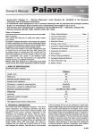
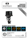
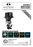
EN / Installation Manual
06 / 2013
SMART 10/18 and SMART10S/18S
ULTRASONIC ANTIFOULING
Package Contents
1.
2.
3.
4.
5.
6.
Installation manual
Generator
Ultrasonic transducer with mounting ring (SMART 18/S, 2 pieces)
Cable for battery connection
Special glue
Sandpaper and alcohol wipe
Introduction
Ultrasound is mainly used in industry, medicine, for cleaning purposes… Our device works on the principle of
converting electrical energy into mechanical energy through a transducer. The transducer transmits ultrasonic
vibrations that resonate through the hull of the boat and thus prevents the formation of biofilm on the hull.
Ultrasonic vibrations also create cavitation effect below the water surface. Cavitation effect destroys the cells of
microorganisms and stops them from adhering to the underwater part of the hull. Microorganisms and biofilm are
food for algae and seashells that adhere to the hull and underwater parts of a boat, such as rudder, propeller…
Ultrasonic antifouling is environmentally friendly.
Follow the instruction manual and thus correctly install the device. The hull of the boat and underwater parts of the
boat will stay clean for a few seasons. Underwater anodes can be replaced during a lift-out or in the water.
SMART 10S and SMART 18S can be set to work in time intervals to save energy without reducing the effectiveness.
Device also has an integrated solar voltage regulator and is therefore self-sufficient if you have a 30-200 Watt
solar panel and an accumulator in good condition.
Warning
Install the ultrasonic device on the boat after cleaning the hull thoroughly and applying the antifouling paint. Device
will prevent the growth of organisms and partly clean the hull. Place the device on the inside of the boat.
Device is suitable for plastic and metallic hulls (aluminum, iron).
Please read and follow the installation manual carefully! In order for the device to work properly it has to be
installed correctly, especially the ultrasonic transducer.
Technical Specifications
Power supply voltage: 12V DC
Highest power output: 40W
Average power consumption: 250mA at 12V
Voltage of transducer: 250V (to 800V p-p)
Input voltage of the solar panel: 12V (to 22V) SMART10S/18S
Highest power output of the solar panel: 200W SMART10S/18S
Protection: Generator IP64 / Transducer IP68
2
The location of transducer
SMART 10 – Boats up to 10 meters (33 feet)
Motorboat with regular drive shaft. Transducer is positioned above the shaft, in between where the shaft exits the
hull and the propeller is positioned, approximately 20 cm to the left or right from the middle of the hull.
Motorboat with sterndrive. Transducer is positioned approximately 10 cm from the edge of the stern and
approximately 20 cm to the left or right from the middle of the hull.
Sailboat. Transducer is positioned above the shaft, in between where the shaft exits the hull and the propeller is
positioned, approximately 20 cm to the left or right from the middle of the hull.
SMART 18 – Boats up to 15 meters (50 feet)
Motorboat with regular drive shaft. Transducer is positioned above the shaft, in between where the shaft exits the
hull and the propeller is positioned, approximately 20 cm to the left or right from the middle of the hull. The
additional transducer is positioned behind the bowthruster back from the bow of the boat and approximately 20 cm
from the middle of the boat towards the bow of the boat.
Motorboat with sterndrive. Transducer is positioned approximately 10 cm from the edge of the stern and
approximately 20 cm to the left or right from the middle of the hull. The additional transducer is positioned behind
the bowthruster back from the bow of the boat and approximately 20 cm from the middle of the boat towards the
bow of the boat.
Sailboat. Transducer is positioned above the shaft, in between where the shaft exits the hull and the propeller is
positioned, approximately 20 cm to the left or right from the middle of the hull. The additional transducer is
positioned behind the bowthruster towards the keel and approximately 20 cm from the middle of the boat towards
the bow of the boat.
SMART 18 + SMART 10 - Boats up to 18 meters (59 feet)
For bigger boats up to 18 meters two transducers are positioned on the stern - above both shafts approximately 20
cm from the middle of the hull. The third transducer is positioned behind the bowthruster back from the bow of the
boat, approximately 20 cm to the left or right from the middle of the boat. For the motorboats with sterndrive the
same rules apply, except on the stern, where the transducers are positioned approximately 10 cm from the edge of
the stern and approximately 20 cm to the left or right from the middle of the hull.
Boats over 18 meters (59 feet) – on order!
Boats up to 10 meters (33 feet)
Transducer on the stern above the propeller
Transducer on the stern above the propeller
3
Boats up to 18 meters (59 feet)
Transducer on the stern above the propeller,
the second one in front of the bowthruster.
Transducer on the stern above the propeller,
the second one behind the keel.
Transducer is installed on the inner side of the hull. It has to be installed on the location, where there is no additional
reinforcement of the hull and no shaft bearer 20-30 cm around. If you have a “sandwich” hull, you will need to
remove a small section of inner core allowing the transducer to make contact with the outer skin of the hull.
The installation of transducer
Warning! The device will work properly only if the transducer and the surface of the hull mate perfectly.
Transducer mounting location should be flat
surface so that the transducer will have a good
contact. Place of the transducer, good sand with
the sandpaper, which is included in the package.
The color is not allowed to bonding the
transducer!
Wipe it with an alcohol wipe clean well, to
degrease and clean the dust. Similarly wipe
Transducer. Wait 5 minutes to dry well.
4
Important. Use the supplied adhesive Epoxy 2K.
Read the instructions supplied with the glue!
From each tube squeeze the same amount. Mix
well about 1 minute. The transducer apply mixed
adhesive and push hard on the location of the
bonding. Glue up and running after a few minutes
Stabilized cross of adhesive tape (recommended).
Adhesive reaches its strength after 1h.
Leave it to dry 1h!
TRANS. 1
SMART 10 / 18
Use the transducer with 4.2 meter long cable for
the stern and the transducer with 8 meter long
cable for the bow.
. Do not wind the cable because of the coil effect!
5
The installation of generator
The best position for the generator is near the battery you attempt to plug into. The cable for battery connection is
2.5 meters long. The position of the installation depends on the length of the cables of transducers and generator.
Remove the lid from the generator and fit it with screws on the wall or any other convenient place. We suggest you
place the generator in a room with other electrical devices. Run the cable of the transducer through the cable gland
of the generator and connect it to the connectors J1 and J2 (SMART 18). Polarity is not important. Fasten the cable
glands. Make sure that the switch is in the OFF state.
Connect the supply cable to the connector J4 (red mark + / black mark -) and directly to the 12V battery. If you have
a solar panel, connect it to the connector J3 (red mark + / black mark -). Connect the cable of the solar panel to the
generator first, and then to the panel. First connect the + pole, then the - pole!
Turn the switch to ON. A bright red LED diode POWER ON and green LED diode OPERATION ON will turn on. After 10
seconds a diode HEAD2 will turn on, because SW2 (SMART 18) switches every 10 seconds.
Approach the transducer and you will hear a quiet clicking, which means that the generator is working properly.
J1 = transducer 1 (HEAD 1)
SMART 10
polarity is not important
black – black
J2 = transducer 2 (HEAD 2)
SMART 18
polarity is not important
black – black
J3 = solar panel 12V
(black mark - / red mark +)
J4 = battery 12V
(black mark - / red mark +)
SW2 = setting of time interval between
transducer 1 and transducer 2 (Smart 18)
DIP1 ON = 5 seconds
DIP2 ON = 10 seconds (preinstalled)
DIP3 ON = 20 seconds
DIP4 ON = 40 seconds
SUM = 75 seconds
SW1 = operate /pause time interval
DIP1 ON = 1 minute
DIP2 ON = 2 minutes
DIP3 ON = 4 minutes
DIP4 ON = 8 minutes
SUM = 15 minutes
All of them OFF = no pause (preinstalled)
6
POWER ON – RED 5mm LED diode – the battery supplies power
OPERATION ON – GREEN 5mm LED diode – generator and transducer are working properly
HEAD 2 – GREEN 5mm LED diode – transducer 2 (SMART 18) is working properly
<10.5V – RED 5mm LED diode – diode is on if the voltage of the battery drops to under 10.5V; the device stops
working
SOLAR – ORANGE 5mm LED diode – the electric power is provided by the solar panel:
- diode is not on – wait for 10 minutes for the battery power to be measured; the solar panel is not
connected, or it is nighttime
- diode is on – the battery is charging
- diode is flashing for aproximately every 5 seconds - the battery is fully charged
We suggest you set the device to work without a pause; SW1 – all switches OFF. This setting is suitable for boats that
have a solar panel or are connected to electrical grid. For other boats set time intervals of operating on SW1. You can
set up to 15 minutes of operating time and 15 minutes pause.
SW1 example 1: switch 1 ON, switches 2, 3, 4 OFF – 1 minute of operating and 1 minute pause
SW1 example 2: switch 2 and 4 ON, 1 and 3 OFF – 10 minutes of operating and 10 minutes pause
Generators SMART 10S and SMART 18S already have an integrated solar voltage regulator, so that you only need a
30-200W solar panel and a connection to the generator. In this way the device is self-sufficient and you do not need
to connect the boat to the electrical grid. Connect the cable of the solar panel to the generator first, and then to the
panel. First connect the + pole, then the - pole!
SMART 10 / 18
SOLAR PANEL
12V / 30 - 200W
OTHER DC 12V
CONSUMERS
(refrigerator, lighting,
...)
TRANS. 1
TRANS. 2
SERVICE BOARD
BATTERY 12V
7
Maintenance
Devices SMART 10 and SMART 18 do not require any maintenance. Check the transducers periodically. They work
properly if you hear a quiet clicking.
In the event that the transducer lose contact with the hull, turn the power off at the main switch and repeat
bonding. Use epoxy glue.
If the device is not working, open the generator housing and check the condition of LED diodes. Check the power
supply from the battery and reset the device using the main switch. Check the electrical fuses F1 and F2.
If you do not manage to resolve the problem, do not hesitate to contact us on the following e-mail address:
The warranty period of the device is 2 years upon presenting the copy of the receipt.
www.smart-antifouling.com [email protected].
8