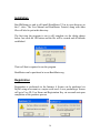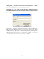
1
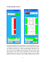
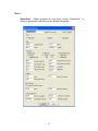
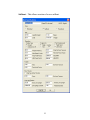
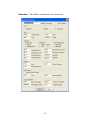
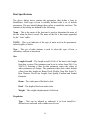
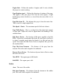
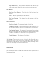
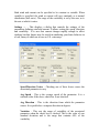
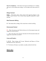
BoatMaster V2
User Manual
Revision B0207
Website:
Email:
www.BoatMaster.org
[email protected]
Table of Contents
Introduction..........................................................................................................................3
Overview..............................................................................................................................4
Docks............................................................................................................................... 6
Boats................................................................................................................................ 8
Parameters and Allowed Values.......................................................................................9
Program Operation.............................................................................................................10
Controlling the view...................................................................................................... 10
Running the simulation.................................................................................................. 11
Moving the boat ............................................................................................................ 11
Using the keyboard for Bridge Controls........................................................................ 11
Default Bridge Control Keys ........................................................................................ 11
Using the Bridge Control Console (BCC)..................................................................... 12
Bridge Controls common to all BCC configurations.....................................................13
Combined Bridge Controls............................................................................................ 15
Separated Bridge Controls............................................................................................. 17
Menu Bar Items..................................................................................................................18
File................................................................................................................................. 18
View............................................................................................................................... 19
Control........................................................................................................................... 19
Docks............................................................................................................................. 19
Boat................................................................................................................................ 20
Environment...................................................................................................................27
Help................................................................................................................................29
Toolbar Items..................................................................................................................... 29
Simulation Control.........................................................................................................29
Bridge Controls..............................................................................................................30
Boat Parameter Editing.................................................................................................. 30
Environment Control..................................................................................................... 30
Lines and Fenders.......................................................................................................... 30
Dock Lines......................................................................................................................... 30
Fenders...............................................................................................................................32
Initial location of the boat.................................................................................................. 33
Advanced Settings............................................................................................................. 33
Wind...............................................................................................................................35
Drag................................................................................................................................36
Prop Walk.......................................................................................................................36
Rudder............................................................................................................................36
Bow Thruster................................................................................................................. 37
Dock Lines..................................................................................................................... 37
Accelerations..................................................................................................................37
Installation..........................................................................................................................38
Registration........................................................................................................................ 38
2
BoatMaster is software that accurately simulates the maneuvering and docking
of a boat. It allows the user to configure a motorboat, sailboat or houseboat
and to operate that boat under varying conditions of wind and current. Dock
lines and fenders can be used in conjunction with several dock
configurations. This flexibility allows the user to set up different boat
configurations and to vary the conditions used to practice boat handling and
docking techniques.
The BoatMaster software can be downloaded, installed and run up to five
times as a fully functional demo. The only limitation is that the user is not
allowed to save any boats defined while running in demo mode.
Introduction
Welcome to the newest version of BoatMaster. Version 1 has been widely
used in the U.S. and across the globe from Australia and Japan to Eastern
Europe, and has now been updated and improved.
If you’re a past user, you may recognize some of your requests, as we take
your observations very seriously. If you’re new to boating and to
BoatMaster you’ll benefit from the numerous updates.
New in this version is the ability to define and save multiple boats. Three
different types of boats are available, as is support for both inboard and
outboard engines. This version has a 3D element, added not to simulate
reality in the world, but to make the experience a bit more lifelike. We’ve
added the ability to deploy fenders in docking, multiple dock configurations,
and more subtle changes have generally improved the ease of use.
You might be interested in observations and comments we’ve received. In
general, users have approved and enjoyed the program as it was, and many
commented very favorably, but there were two basic objections that surfaced
in user contacts with us, and on various Newsgroups.
Some people objected that BoatMaster wasn’t “game like.” Our response is
that this program, while fun and quite engaging is NOT a game, and is
intended to help its users make of themselves better and safer boaters.
3
Nonetheless, I still love “playing with it,” and if you find yourself being
entertained as well, well, “what’s in a name?”
Another objection was that “you cannot learn boat handling on a simulator.”
This is a use-specific manifestation of an age old, and old age, complaint.
This has been disproven millions of times by tens of thousands of pilots who
mastered multiple aircraft emergencies and routine operations using
simulators. As an experienced pilot and a very experienced boater, I
maintain that the only thing that you cannot do in a simulator is kill yourself
or ruin your boat or airplane. It is true that you cannot master the whole of
boat handling or flying an airplane in a simulator, but you can learn the
procedures safely and economically.
BoatMaster is a true simulator. It simulates the physics of boats and their
interaction with the wind and water. This new version allows multiple ways
to configure the interactions of the boat and of the elemental forces of
boating, so it has an even more realistic “feel.” Set up conflicting, rapidly
changing wind and current configurations and try putting your boat into a
small slip, between adjacent yachts, and see if you don’t find that challenge
realistic. We’re betting you will, and that you’ll love it.
Overview
This software simulates the motion of a boat, as caused by forces acting
upon it. The major sources of these forces are props, rudders, bow thrusters,
fluid drag, lines, dock contacts, wind, and current flow.
The main program window is shown below.
4
This is a typical window with menu and tool bars and a status line at its base.
OpenGL is used to model and render the 3D scene.
The boat shown in the window above is performing a docking maneuver in a
slip. The dock is the default configuration that has a slip and pilings. The
blue arrows indicate current and its direction, and the red arrow on the top of
the boat shows the direction and force of the wind.
An optional Bridge Control Console (BCC) dialog is shown on the left side
of the window. The BCC allows control of the boat with a mouse via buttons
and sliders. The boat can also be operated with the keyboard.
In this case the boat is a twin engine motorboat. Both its engines are in
forward as is shown by the green bars in the cockpit, and there is some port
rudder being applied shown by the red bar at the transom. A spring line is
being used to pull the boat to the dock. The boat has four fenders deployed.
5
Docks
BoatMaster has three dock configurations that can be used to simulate most
boat handling and docking situations.
The sizes of the docks are automatically adjusted to fit the size of the boat
being simulated. However, a user can customize the size of any dock
configuration.
All the configurations except the combination shown below can be rotated to
four orientations, 90 degrees apart.
The above is the default configuration and is a combination of a slip and a
set of pilings.
6
The above configuration contains a standard slip and a side slip that is used
to represent docking in a confined space such as between other boats at a
wharf or a fuel dock.
7
The configuration above is simply a wharf and a set of pilings that can be
found anywhere in the world. The wharf, when rotated so it is at the bottom,
can be used to simulate a beach when parking a houseboat. It is also a good
way to practice backing into a dock or sea wall off an anchor line, as is often
done in Europe.
Boats
There are three boat types supported in BoatMaster - motorboats, sailboats
and houseboats. These boats are depicted in configurations that are typical
classical forms. These configurations are scaled to fit the sizes specified by
the user and are shown below.
These boats all share graphics that are used to convey information to the user
and to allow functions of the program to be used.
8
The dark gray dot near the bow of the motorboat shows the location of the
bow thruster and will have a red or green bar extending to its side when the
bow thruster is active.
The dark gray dot about a third of the way from the bow is the location of
the Center of Rotation (CR) of the boat. This is the point that the boat rotates
about when it turns.
The dark gray dots in the cockpits represent the engines and will have red or
green bars extending vertically when the props are engaged.
The dark gray dot near the stern represents the rudder and will have red or
green bars extending to its side it to indicate the amount and direction of
rudder being applied.
The cyan colored dots at the deck edges of the boats represents the location
of the cleats where lines can be attached.
Parameters and Allowed Values
Units of Measure – The BoatMaster user interface uses either English or
Metric Units. English units are pounds, feet and square feet. Metric units are
kilograms, meters and square meters. Speed is always in knots and angles
are always in degrees.
When values representing any of these units are present in this manual they
will be shown using the convention; English(Metric).
The following is a list of the major program parameters that can be set by the
user and the range of their allowed values. There are many parameters that
are not in this list and are addressed in the sections that describe how to use
them.
Boat length (LOA)
Boat beam
Boat draft
Boat weight
20(6.1) to 100(30.5)
20% to 40% of the LOA
0.5(0.15) to 10(3)
1,000(454) to 250,000(113,400)
9
Engine type
Number of engines
Inboard or Outboard
1 or 2
Bow thruster
yes / no
Lines
Fenders
9 max
10 max
Wind
Current
0 to 30 knots
0 to 5 knots
Program Operation
Controlling the view
Since this is a 3D view, it is seen as if viewed through a camera looking
down on the CR of the boat. The vertical position of the camera can be
positioned from 80 feet high down to 4 feet above the cabin top. The user
can also zoom in and out as if using a telephoto lens.
Using the Mouse Wheel to control the view
The mouse wheel can be used to control the view of the boat as seen by the
user. Moving the wheel forward or backwards zooms in or out respectively.
Moving the wheel forwards or backwards while holding the shift key down,
moves the lens up or down respectively.
Using the Keyboard to control the view
Positioning the camera vertically is done with the Page Up and Page Dn
keys. Zooming in and out is controlled by the + and - keys.
10
Running the simulation
The simulation is started, stopped and reset using the buttons on the toolbar
or function keys as described below. Initially, the simulation is stopped as
indicated by the depressed pause button on the toolbar. Press the start button
to start the simulation.
You can exit via the “Esc” key, the file>exit menu sequence or the title bar
exit button.
When initially run, the program shows a view of a dock with a slip and
pilings and the boat.
Moving the boat
This is accomplished via the keyboard or via a Bridge Control Console
(BCC).
Using the keyboard for Bridge Controls
All control of the boat’s motion is available using the keyboard. This is
probably the easiest way to run the boat. It allows you to maneuver the boat
without having to look at something other than the boat.
You may also use both methods to control the boat. Activating the BCC
while using the keyboard control, allows you both ease of control and clear
visualization of the forces you’ve applied.
The keys used to control the boat are shown below.
Default Bridge Control Keys
Function
Key
Start and pause the simulation
Reset the simulation
F1
F2
11
Terminate running of the program
Esc
Right rudder increment
Rudder amidships
Left rudder increment
L
K
J
Single or twin engine
All forward throttle increment
All stop
All reverse throttle increment
E
D
C
Twin engine – Port
Forward throttle increment
Engine stop
Reverse throttle increment
W
S
X
Twin engine – Starboard
Forward throttle increment
Engine stop
Reverse throttle increment
R
F
V
Bow Thruster
Port
Stop
Starboard
U
I
O
Using the Bridge Control Console (BCC)
These pop up dialogs allow the user to control the boat via mouse clicks on
buttons and on the scroll bars, in addition to the control keys described
above. Colors are used to show the status of the various settings. Red is used
to represent Port and Reverse. Green represents Starboard and Forward.
Dark gray is used to show a neutral status in the scrollbars and buttons.
12
A BCC can be invoked by pressing the button with the ships wheel on it on
the controls bar or from the Control drop down menu. This menu also allows
the selection of either the combined or separated BCC configurations
defined below. The choice is made by using the Control>Bridge menu, then
choosing desired configuration.
There are two choices, one for a BCC that utilizes the combined engine and
throttle controls and one that has these controls separated.
Combined controls, often called “Morse Controls,” are usually encountered
on outboards and smaller inboards. The control has one handle per engine
that moves forward and backwards to engage both the transmission direction
and the throttle, with the center position putting the engine in neutral at idle
speed.
Separated controls have two control handles per engine, a separate handle
for each transmission and engine throttle. The transmission control has three
positions, forward, neutral and reverse. The throttle control moves between
two extremes, idle and full throttle.
The four BCC configurations that are used to implement these controls
consist of sets of buttons and scroll bars. Each configuration also includes
controls for a bow thruster and the rudder. They are shown below.
Bridge Controls common to all BCC configurations
The bow thruster is controlled by a set of buttons that activate the thrust in a
direction to move the bow to port or starboard and a button that deactivates
that thrust.
The rudder is controlled by a combination of buttons and a scroll bar. The
scroll slider shows the position of the rudder. The background color is green
if the rudder is to starboard and red if to port. It is colored dark gray when
the rudder is amidships. The buttons provide an easy way for the user to
position the rudder hard to port or starboard or amidships. The rudder can
also be moved by any of the standard scroll bar controls as described below.
13
At the bottom of each BCC are two buttons. The one labeled CANCEL
removes the BCC dialog box from the screen. The other button is used to run
or pause the simulation. The action that will be performed when the button is
pressed is shown on the button.
Engine RPM is shown below the throttle scrollbar for each engine.
14
Combined Bridge Controls
The combined engine control is represented by vertical scroll bar(s) and a set
of buttons as shown above. When the slider is at the mid position the engine
is at idle and in neutral. This is shown by a dark gray background color on
the scrollbar and a dark gray on the neutral(N) button. The slider can be
moved by any of the standard scroll bar controls. When the slider is in the
upper portion of the scroll bar the background is green and the slider
position indicates the amount of forward engine throttle being used. When
the slider is in the lower portion of the scroll bar it indicates reverse and the
15
background color will be red. In general, the slider position indicates what is
happening at the prop.
The scroll bar slider controls engine direction. When the slider is moved in
either direction past neutral, the engine will change direction, and the color
will change accordingly. The rudder control operates the same way.
The buttons are used to set the engine to full forward (FF), neutral (N) and
full reverse (FR). The FF button will be green when the engine is at full
forward. The FR button will be red when in full reverse. The N button will
be dark gray when the engine is in neutral and light gray otherwise.
When the BCC commands a boat with twin engines, a third set of three
buttons is located between the port and starboard button sets. These buttons
are used to control both engines synchronously. Put both engines in neutral
with the N button. The FWD and REV buttons increments the throttle of
both engines in the respective direction. Pressing the N button and then
either the FWD or REV button (repeatedly) effectively synchronizes the
engines.
16
Separated Bridge Controls
The operation of the separated engine controls is similar to the equivalent
elements of the combined controls. The buttons labeled FWD, N, and REV
operate the transmission and will be colored to show their status. Full
throttle is initiated by pressing one of the FULL buttons located above the
appropriate scroll bar when the associated transmission is engaged. The third
set of unlabeled buttons present in the twin engine BCC performs the same
17
functions as the buttons next to them, except that the operation will be
applied to both engines.
The scroll bars operate the same as in the combined BCC except the slider
behaves differently. When the slider is at the bottom, that engine is in neutral
and no propulsion forces are being generated by its prop. When an engine is
in forward or reverse the slider will show some value above zero. The lowest
the slider can go is the idle position of the throttle. When the slider is at the
top, the engine is at full throttle. In general, the slider position indicates what
is happening at the prop. The RPM indicated below the scrollbar indicates
the engine throttle status.
Twin engines can be synchronized using the SYNC button. It is colored light
gray when the engines are not being synchronized. Pressing the button will
synchronize the engines. When the engines are synchronized that button
will be colored green and will decouple the engines when pressed.
When the engines are synchronized any action performed on the port engine
will also be applied to the starboard engine. The scroll bar for the starboard
engine will mimic that of the port engine. Any actions attempted on the
starboard engine will be ignored while the engines are synchronized.
Menu Bar Items
File
English Units – This selection causes the BoatMaster user interface to use
the English Units of pounds, feet and square feet.
Metric Units - This selection causes the BoatMaster user interface to use the
Metric Units of kilograms, meters and square meters.
Exit – This selection will terminate execution of the BoatMaster program.
18
View
Toolbar – This selection will toggle the display of the toolbar.
Status Bar – This will toggle the display of the Status Bar at the bottom of
the window.
Control
Run – Starts the simulation running.
Pause – Pauses the running of the simulation.
Reset – Resets the simulation to the default conditions.
Bridge
Separate Shift and Throttle – Shift and throttle are in separate
controls.
Combined Shift and Throttle – Shift and throttle are in one control.
Docks
Slip size
Auto – This selection causes the size of a slip to be set to the smallest
standard sized slip that the boat will fit in with 40% of clearance in
length and 100% in beam. If a standard sized slip is not available that
meets this requirement a custom slip is constructed and selected.
10 x 20, 13 x 30, 16 x 40, 19 x 50, 22 x 60 – These are the standard
slip sizes found in most marinas. Selecting one of these will set the
slip size independent of boat size.
19
Custom – This will provide a dialog box that allows specification of a
custom slip size.
Slip and Pilings – This selects a dock configuration that has a slip and a set
of pilings.
Slips - Bottom
Slips - Right
Slips – Top
Slips – Left – This selects a dock configuration that has two slips. One is a
standard slip and the other is a side slip to simulate docking along a wharf
between other boats in front and behind your space, or approaching a gas
dock when other boats are already fueling. There are four configuration
rotations where the standard slip has its entrance at the bottom, right, top or
left.
Pilings - Bottom
Pilings - Right
Pilings – Top
Pilings – Left – This selects a dock configuration that has a wharf and six
pilings. The configuration is rotated to provide a geometry where the pilings
are at the bottom, right, top or left side of the screen.
Boat
Boats are contained in boat files that are stored on the computer in the
“BoatMaster V2” directory. Initially no boat files are defined. A maximum
of 16 boat files are available to the BoatMaster program.
20
To define a boat use the Boat>New menu item and select the type of boat
you wish to define. The choice is Motorboat, Sailboat or Houseboat. A
dialog will be opened where you can enter the various parameters that define
a boat. If you select the OK button, these parameters will be used to generate
the current boat. You can run the simulation using this boat, or change the
parameters via the Boat>Edit menu item until the performance of the boat
approximates your own boat. You can then use the Boat>Save menu item to
save the boat using the filename defined in the parameters.
When you wish to run the simulation with a boat that has been previously
saved you can load it using the Boat>Open menu item. This will read the
boat file and make it the current boat.
Boats that you no longer need can be deleted using the Boat>Delete menu
item.
Open … – This will display a dialog box that allows the user to load one of
the boat data files (if any have been saved).
Edit – Allows editing of the data for the currently loaded boat.
Save – Allows saving of the current boat in a boat data file for future use.
Delete … – This allows deletion of one of the boat data files previously
saved.
21
New >
Motorboat – Allows creation of a new boat of type “Motorboat”. A
dialog is presented with data for the default motorboat.
22
Sailboat – This allows creation of a new sailboat.
23
Houseboat – This allows creation of a new houseboat.
24
Boat Specifications
The above dialog boxes contain the parameters that define a boat in
BoatMaster. Each type of boat is initially defined with a set of default
parameters. The user should change these values to match his own boat. The
contents of this dialog are defined in the following.
Name – This is the name of the boat and is used to determine the name of
the file when the boat is saved. The name of the file is this name appended
by the “.boat” suffix.
UNITS – This is an indicator of the type of units used in the parameters,
either English or Metric.
Type – This set of radio buttons is used to select the type of boat, a
motorboat, sailboat or houseboat.
Size
Length Overall – The length overall (LOA) of the boat is the length
from bow to stern. This parameter can be set to values from 20(6.1) to
100(30.5). Entering a value for this parameter causes the values of
other parameters to change. The parameters that derive their default
values from this length are Beam, Draft, Weight, Prop Dist from CL,
Bow Thruster, Dock Line Length, Line Spring Constant and Fender
Diameter.
Beam – The widest part of the boat’s deck.
Draft – The depth of the boat under water.
Weight – The weight (displacement) of the boat.
Propulsion
Type – This can be inboard or outboard. A jet boat should be
defined as an outboard with a rudder area of zero.
25
Engine Info – Defines the number of engines and if a twin, whether
the props are counter rotating.
Prop Rotation (port) – Defines the direction of rotation of the prop.
This applies to the port prop if the boat has twin engines. A right
handed prop rotates clockwise as viewed from the stern while it is in
forward.
Prop Dist from CL – The distance the prop is from the center line.
This is zero for a single engine boat.
Max Speed – Knots – The maximum speed of the boat in knots.
Prop Walk Factor – This is a scaling factor that adjusts the amount
of prop walk. Adjust this value to approximate the handling of the
simulated boat.
Idle Power Factor – The fraction of full power applied at the Idle
RPM. A good way to determine this factor for your boat is to allow it
to attain a constant speed when the throttle is at idle and note the
speed. Then adjust the Idle Power Factor to duplicate this speed for
the simulated boat.
Prop Dist from Transom – The distance of the prop from the
transom. This value can be negative for outboards.
Reverse Power Factor – The fraction of power that is effective when
the boat is in reverse.
Max RPM – The engine rpm at full throttle.
Idle RPM – The engine rpm at idle.
Rudder
Area – The area of the rudder.
Dist from Transom – The distance from the transom to the rudder
post. This value can be negative for outboards.
26
Prop Wash Factor – This parameter determines the effect of prop
wash on the rudder. Adjust this value to set how fast the boat turns.
Bow Thruster
Boat has a Bow Thruster – Check this box if the boat has a bow
thruster.
Force – The force generated by the bow thruster.
Dist from Transom – The distance from the transom to the bow
thruster.
Lines and Fenders
Dock Line Length – The maximum length of a dock line.
Anchor Line Length – The maximum length of the anchor line. Any
line attached to the bow of the boat is considered to be an anchor line.
Line Spring Constant – The amount of force generated by stretching
the line a unit length. This value should not be changed under normal
conditions. It defaults to a value based on the weight of the boat.
Fender Diameter – The diameter of the fenders.
Adv Settings - This provides access to a dialog box that allows the user to
customize the effects of the various forces acting on the boat. This allows
customization of the behavior, or feel, of the boat while performing various
maneuvers. This dialog is discussed in detail below.
Environment
The environment consists of wind and current that can be specified via an
Environment dialog.
27
Both wind and current can be specified to be constant or variable. When
variable is specified, the wind or current will vary randomly as a normal
distribution (bell curve). The range of the variability is set by the user, as is
the rate at which it varies.
Settings … – This displays a dialog that controls the settings of the
parameters defining wind and current. It allows setting the speed, direction
and variability. It is rare that current changes rapidly enough to affect
docking, but this feature may be useful in simulating your boats behavior in
a lock, many of which are in use on U.S. waterways.
Speed/Direction Varies – Checking one of these boxes causes the
associated parameter to vary.
Avg Speed – This is the average speed of the parameter. It is a
constant value if the above check box is not checked.
Avg Direction – This is the direction from which the parameter
comes. It is specified as a compass direction in degrees.
Variation – This sets the range of variability of the associated
parameter when the check box is checked. This is the value of one
standard deviation and is the range that contains 68% of the
variability.
28
Rate of Change – This determines how fast the parameter will vary
when the check box is checked.
Wind – This selection allows the user to toggle the wind on and off, as
defined in the settings. The direction and magnitude of the wind is shown as
a red arrow on the cabin top.
Current – Same as above for current flow. The direction and magnitude of
the current is shown as many blue arrows on the water area.
Help
About – Displays Copyright and Version information for BoatMaster.
Keyboard Control Keys – Displays the keyboard keys used to control the
boat and simulation.
Lines and Fenders – Displays controls used to manage lines and fenders.
Toolbar Items
The toolbar contains buttons that provide the same function as some items in
the menus. It is just a “single click” way to perform actions that are used
often. Buttons that have been selected will be shown as depressed.
Simulation Control
Start the Simulation – Performed by clicking the button with the right
pointing green arrow head.
Pause the Simulation – The button with the two red vertical bars will pause
the simulation.
29
Reset the Simulation – This button will stop the simulation if it is running
and reset it to the default start settings. It is the button with a blue square on
it.
Bridge Controls
Bridge – This button with a ship’s wheel will toggle the display of the
Bridge Control Console. This is useful when using the keyboard to control
the boat.
Boat Parameter Editing
B – This button allows editing of the current boat via the boat dialog.
Environment Control
W – This is the same as the Wind selection in the Environment menu and
toggles the wind on and off.
C – This is the same as the Current selection in the Environment menu and
toggles the current flow on and off.
Lines and Fenders
L, H, R – These buttons will Loosen, Hardened and Remove all lines
attached to the boat, respectively.
F – This button will remove any fenders currently attached to the boat.
Dock Lines
30
Dock lines can be attached to the boat at the locations shown as colored
circles located along the deck edge. These are colored cyan when no lines
are active at that attachment point. In this manual, attachments at cleats are
numbered from fore to aft as the #1, 2, 3 and 4 positions. The centerline bow
attachment is for an anchor and is not numbered.
To attach a dock line, Left Click (LC) the attachment point to select where a
line is to be attached on the boat. The attachment point selected will turn
yellow.
Next, LC a point on the dock for attachment of the dock end of the line.
(Note: you can attach the dock end of the bow line to the water to simulate
an anchor.) If the line is long enough, the line will be attached, and it and the
attachment points will turn green in color.
To harden an attached line, LC the line. The line will be shortened to the
current distance and the attachment point on the boat will be shown as red in
color. The red color is also used to indicate anytime a line is tight, as would
happen when moving the boat against the line. Any line that has been
hardened will always have the circle at the boat attachment point shown in
red even if the line is not tight.
The sequence shown below is of a boat coasting into a slip while it sets a
spring line to pull it to the dock. The left shot shows the deck cleat has been
selected. The next shot shows the line attached to the dock and the third
shows the line has been hardened. Four fenders have been deployed on the
dock side of the boat
31
To loosen a line Right Click (RC) it. The length of the line will be set to the
maximum length.
To loosen all hardened lines use SHIFT>LC. The length of the lines will be
set to the maximum length.
To detach a line, Shift>RC on the line.
The L, H and R buttons on the toolbar will also Loosen, Hardened and
Remove all lines attached to the boat, respectively.
When a tight line builds up too much tension, initially, instead of it breaking,
it will act as if it is slipping at the cleat. If it slips to the point that it is at its
maximum length, it will stop slipping and the force will continue to build
until it breaks. The default breaking point is a force that is 10 times the line’s
effective spring constant. See the Boat and Adv Settings Dialogs for setting
the parameters associated with dock lines. It should rarely be necessary to
change the default parameters.
Fenders
Up to 10 fenders can be located around the deck edge. Fenders are shown as
a black circle. See the screen shot in the lines discussion above. The size of a
fender shown in a new boat dialog is initially set based on the length of the
boat. It can be changed in the dialog, if another size is desired.
32
To place a fender on a boat, Ctrl>LC somewhere along the edge of the deck.
To remove a fender, Ctrl>RC on the fender to be removed.
The F button on the toolbar will remove all fenders attached to the boat.
Initial location of the boat
The location of the boat prior to the start of the simulation is defined in a
default position and is contained in the saved boat file. This position can be
changed by the user.
To define a new default position, drive the boat to a position that you would
like to use for a starting position, and then pause the simulation (F1). Press
F12 to record this position as the new starting position for the simulation. In
the future, when the simulation is reset, this is the position that will be used
to position the boat. If you then save the boat, this new starting position will
be saved along with the other boat parameters.
The location can be set back to its original default position by pressing the
F11 key when the simulation is paused. If you then save the boat, this new
starting position will be saved along with the other boat parameters.
Advanced Settings
The Advanced Settings contain the parameters that control the equations of
motion during the running of the simulation. These parameters are a function
of the type of boat being simulated and are assigned default values that will
be correct for the majority of boats.
Some boats have behaviors that are not properly modeled by the default
settings. Therefore we have provided access to these settings to allow the
user to adjust certain parameters to better represent the boat being modeled.
In low speed maneuvers such as docking, it’s rarely necessary to change
these parameters, and we recommend that you do so only if your boat is
distinctly different from our default boats.
33
The user should be aware that changing these settings can result in an
unstable simulation and may even cause the program to lock up,
requiring use of the Task Manager to end its execution. This is because
many of the parameters are interrelated. Therefore when changing any
of these parameters change only one parameter at a time and use small
changes.
These parameters are changed via a dialog presented as the result of using
the “Adv Settings” entry in the Boat drop down menu.
The dialog, shown below, presents the parameters in groups of related
values. These parameters are dimensionless constants that adjust the effects
of the forces in the equations of motion. These groups and their parameters
are discussed below.
Any force being applied to a boat can be assumed to produce two types of
motion, translational and rotational. The translational motion results from
the force as if it was acting through the CR of the boat. The rotational
motion results from a torque that is a function of the amount of force and the
perpendicular distance between the line of the force and the CR.
Translational forces are usually broken down into their axial and lateral
components and are treated as such in the Adv Settings dialog.
34
Wind
When the wind blows against a boat the force that results is primarily a
function of the presented area and the speed of the wind. That force can be
considered to be applied at a point on the boat and causes the boat to move
in the direction of the force. That force also causes the boat to rotate since
the force is not necessarily applied at the CR.
The value of the Presented Area Drag adjusts the amount of force that the
wind generates. The CP Torque value adjusts the amount of torque that force
produces.
35
Drag
When a boat is in motion the water resists that motion by creating opposing
forces. These forces are called drag and come in three forms in this
simulation. Rotational drag resists the boat’s turning. Translational drag
resists motion along the keel and lateral drag, know as skid resistance, resists
sideways movement of the boat. These parameters adjust these drag forces.
Prop Walk
Prop walk is a lateral force generated by the action of a rotating prop against
the water. It is called prop walk because the direction of the force causes the
boat to move in the direction the prop would if it were rolling or “walking”
over the ground. A right handed prop (clockwise rotation) would move to
starboard when going forward.
On most boats, prop walk is more pronounced when the engine is in reverse
than when it is in forward, and that is why there are two parameters for its
adjustment. There are also adjustments available for the lateral and torque
forces. The prop walk factor in the Boat dialog is a multiplier against the
lateral adjustment value in this dialog.
Prop walk is also a function of the speed of the prop through the water and
therefore there is an adjustment for this effect.
Rudder
The forces on the rudder are caused by the velocity of water passing over it
and its angle of attack, controlled by the wheel or tiller. The velocity over
the rudder is composed of two components, the velocity of the boat through
the water and the prop wash caused by the turning propeller.
The Prop Wash Factor in the Boat dialog is an adjustment for the force
caused by prop wash.
36
Prop wash is stronger when the engine is in forward than when it is in
reverse. The value of the Prop Wash Reverse parameter is an adjustment for
this effect.
Adjustments for the turning torque and lateral forces are provided in this
dialog.
Bow Thruster
The bow thruster generates a lateral force and a torque that rotates the boat.
Adjustments for these forces are provided here.
Dock Lines
When the tension in a dock line exceeds a specified limit it will break. The
Break Pt Factor value here is used to set that limit. The limit is the product
of the Break Pt Factor value and the spring constant.
When the tension in a dock line exceeds a specified limit, instead of
breaking, the line is allowed to slip through its cleat. The Slip value here is
used to set that limit. The limit is the product of the Slip value and the spring
constant.
Accelerations
These values are the maximum allowed translational and rotational
accelerations used in the simulation.
There is probably no reason to ever change the Rotational value.
The Trans Max Accel value determines the time required to reach the
maximum speed at full engine power. Since the simulation does not model
the prop and the forces it produces, this maximum acceleration is used to set
the maximum engine forces. If it is desired to change the time required to
reach the maximum speed, it can be done by adjusting the Trans Max Accel.
37
Installation
Run BMSetup.exe and it will install BoatMaster V2 in its own directory on
the C: drive. The User Manual and BoatMaster Tutorial, along with other
files will also be put in this directory.
The first time the program is run it will complain via the dialog shown
below. Just click the OK button and the file will be created and all defaults
established.
That is all that is required to run the program.
BoatMaster can be purchased at www.BoatMaster.org.
Registration
Registration is performed via the Internet. A license can be purchased via
PayPal using an account or a major credit card. A user purchasing a license
will get a User ID, User Name and Registration Key via an email sent upon
completion of the purchase process.
38
While running in demo mode each run will start with a dialog box as shown
above. These dialogs show how many demo runs remain.
Pressing the No or OK button will take the user to another dialog where
registration is performed using the information obtained via email during the
purchase process.
Registration is obtained by entering the information in the above dialog box
and pressing the Register button. Any errors made in the entry of the
information will be announced by other dialogs and corrections and retries
can be performed until registration is completed. Pressing the Cancel button
will terminate the registration process and exit the program.
39