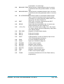
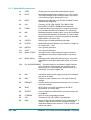
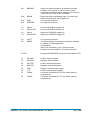
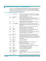
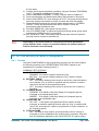
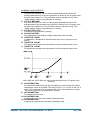
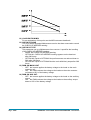
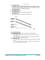
1
ELECTRONIC • OLEODYNAMIC • INDUSTRIAL EQUIPMENTS CONSTRUCTION Via Parma, 59 – 42028 – POVIGLIO (RE) – ITALY Tel +39 0522 960050 – Fax +39 0522 960259 e-mail: [email protected] – web: www.zapispa.it EN User Manual AC-3 FLASH AC-4 FLASH INVERTER Copyright © 1975-2011 Zapi S.p.A. All rights reserved The contents of this publication is a ZAPI S.p.A. property; all related authorizations are covered by Copyright. Any partial or total reproduction is prohibited. Under no circumstances will Zapi S.p.A. be held responsible to third parties for damage caused by the improper use of the present publication and of the device/devices described in it. Zapi spa reserves the right to make changes or improvements to its products at any time and without notice. The present publication reflects the characteristics of the product described at the moment of distribution. The publication therefore does not reflect any changes in the characteristics of the product as a result of updating. is a registered trademark property of Zapi S.p.A. NOTES LEGEND 4 U Page - 2/89 The symbol aboard is used inside this publication to indicate an annotation or a suggestion you should pay attention. The symbol aboard is used inside this publication to indicate an action or a characteristic very important as for security. Pay special attention to the annotations pointed out with this symbol. ADWZP0DF - AC3 FLASH / AC4 FLASH INVERTER - User Manual Contents 1 2 3 4 5 6 7 INTRODUCTION ...................................................................................................................6 SPECIFICATION ...................................................................................................................7 2.1 AC-3 FLASH technical specifications .........................................................................7 2.2 AC-4 FLASH technical specifications .........................................................................7 2.3 Block diagram .............................................................................................................8 SPECIFICATION FOR THE INPUT DEVICES FILLING UP THE INSTALLATION KIT.......9 3.1 Main contactor ............................................................................................................9 3.2 Microswitches .............................................................................................................9 3.3 Accelerator unit...........................................................................................................9 3.4 Other analog control devices ....................................................................................10 3.5 Speed feedback........................................................................................................11 INSTALLATION HINTS.......................................................................................................12 4.1 Wires and fuses ........................................................................................................12 4.1.1 Connection cables ......................................................................................12 4.1.2 Fuse for I/O circuits.....................................................................................12 4.1.3 Fuse for power section................................................................................12 4.2 Installation of the hardware.......................................................................................13 4.2.1 Positioning and cooling of the controller .....................................................13 4.2.2 Connection of power cables........................................................................13 4.2.3 CAN connections and possible interferences .............................................14 4.2.4 I/O connections ...........................................................................................16 4.2.5 Connection of the encoder..........................................................................16 4.2.6 Main contactor and key connection ............................................................17 4.2.7 Insulation of truck frame..............................................................................18 4.3 Hardware protection and safety features..................................................................18 4.3.1 Protection features......................................................................................18 4.3.2 Safety Features...........................................................................................19 4.4 EMC..........................................................................................................................20 4.5 Various suggestions .................................................................................................21 OPERATIONAL FEATURES ..............................................................................................22 5.1 Diagnosis ..................................................................................................................22 DESCRIPTION OF CONNECTORS....................................................................................24 6.1 Connectors of the logic - Traction configuration .......................................................24 6.1.1 Ampseal and Molex Spox connectors.........................................................24 6.1.2 Amp Saab 42 poles connector....................................................................26 6.1.3 Molex Minifit connectors .............................................................................28 6.2 Connectors of the logic - Pump configuration...........................................................30 6.2.1 Ampseal and Molex Spox connectors.........................................................30 6.2.2 Amp Saab 42 poles connector....................................................................31 6.2.3 Molex Minifit connectors .............................................................................34 6.3 Description of power connections.............................................................................36 DRAWINGS .........................................................................................................................37 7.1 AC-3 FLASH mechanical drawing ............................................................................37 7.2 AC-4 FLASH mechanical drawing ............................................................................38 7.3 Connection drawing - Traction configuration ............................................................39 7.3.1 Ampseal and Molex Spox connectors.........................................................39 7.3.2 Amp Saab 42 poles connector....................................................................40 ADWZP0DF - AC3 FLASH / AC4 FLASH INVERTER - User Manual Page - 3/89 7.3.3 Molex Minifit connectors ............................................................................. 41 Connection drawing - Pump configuration................................................................ 42 7.4.1 Ampseal and Molex Spox connectors ........................................................ 42 7.4.2 Amp Saab 42 poles connector ................................................................... 43 7.4.3 Molex Minifit connectors ............................................................................. 44 7.5 Connection drawing - Combi configuration............................................................... 45 7.5.1 Ampseal and Molex Spox connectors ........................................................ 45 7.5.2 Amp Saab 42 poles connector ................................................................... 46 7.5.3 Molex Minifit connectors ............................................................................. 47 8 PROGRAMMING & ADJUSTMENTS USING DIGITAL CONSOLE .................................. 48 8.1 Adjustments via Console .......................................................................................... 48 8.2 Additional programming tools ................................................................................... 48 8.3 Description of Console & Connection....................................................................... 49 8.4 Description of Standard Console Menu.................................................................... 49 8.4.1 Traction configuration ................................................................................. 50 8.4.2 Pump configuration..................................................................................... 51 8.5 Sequence for setting up the parameters .................................................................. 52 8.5.1 Traction....................................................................................................... 52 8.5.2 Pump .......................................................................................................... 52 8.6 OPTION and ADJUSTMENTS configuration............................................................ 53 8.6.1 Traction....................................................................................................... 53 8.6.2 Pump .......................................................................................................... 57 8.7 PARAMETER configuration...................................................................................... 64 8.7.1 Traction....................................................................................................... 64 8.7.2 Pump .......................................................................................................... 65 8.8 TESTER: description of the functions....................................................................... 68 8.8.1 Traction....................................................................................................... 68 8.8.2 Pump .......................................................................................................... 69 9 OTHER FUNCTIONS .......................................................................................................... 72 9.1 Description of Console “SAVE” function................................................................... 72 9.2 Description of Console “RESTORE” function. .......................................................... 73 9.3 Description of “ALARMS” menu ............................................................................... 74 9.4 Description of Console “PROGRAM VACC” function............................................... 75 10 AC-3 / AC-4 FLASH DIAGNOSTIC – ALARM DESCRIPTION.......................................... 77 10.1 Analysis of alarms for Traction controller ................................................................. 77 10.2 Analysis of alarms for Pump controller ..................................................................... 83 11 RECOMMENDED SPARE PARTS FOR INVERTER ......................................................... 88 12 PERIODIC MAINTENANCE TO BE REPEATED AT TIMES INDICATED......................... 89 7.4 Page - 4/89 ADWZP0DF - AC3 FLASH / AC4 FLASH INVERTER - User Manual APPROVAL SIGNS COMPANY FUNCTION INITIALS SIGN PROJECT MANAGER TECHNICAL ELECTRONIC MANAGER VISA SALES MANAGER VISA Publication N°: ADWZP0DF Edition: May 2011 ADWZP0DF - AC3 FLASH / AC4 FLASH INVERTER - User Manual Page - 5/89 1 INTRODUCTION Within the ZAPIMOS family, the AC-3 FLASH and the AC-4 FLASH inverters are the model suitable for control of 9÷22 kW motors;. they have been expressly designed for battery electric traction. Their typical applications are: • electric truck • electric cars • tractors • buses. The are available for battery voltages from 24V to 120V. Both AC3 FLASH and AC4 FLASH can be purchased with three different I/O connectors: • Ampseal 35 poles (plus a Molex Spox connector for the Zapi console) • Amp Saab 42 poles • Molex Minifit Page - 6/89 ADWZP0DF - AC3 FLASH / AC4 FLASH INVERTER - User Manual 2 SPECIFICATION 2.1 AC-3 FLASH technical specifications Inverter for AC asynchronous 3-phase motors Regenerative braking functions Can-bus interface Flash memory (256 Kbytes On-Chip Program Memory) Digital control based upon a microcontroller Voltage ..................................................................... 36/48 V; 72/80 V; 96 V; 120 V Maximum current (36/48 V)........................................................ 600 A (RMS) for 3' Maximum current (72/80 V)........................................................ 600 A (RMS) for 3' Maximum current (96 V).............................................................450 A (RMS) for 3’ Maximum current (120 V)...........................................................500 A (RMS) for 3’ Operating frequency....................................................................................... 8 kHz External temperature range ............................................................. -30 °C ÷ 40 °C Maximum inverter temperature (at full power) ................................................75 °C 2.2 AC-4 FLASH technical specifications Inverter for AC asynchronous 3-phase motors Regenerative braking functions Can-bus interface Flash memory (256 Kbytes On-Chip Program Memory) Digital control based upon a microcontroller Voltage .............................................................................. 36/48 V ; 72/80 V ; 96 V Maximum current (36/48 V)........................................................ 750 A (RMS) for 3' Maximum current (72/80 V)........................................................ 550 A (RMS) for 3' Maximum current (96 V).............................................................550 A (RMS) for 3’ Operating frequency....................................................................................... 8 kHz External temperature range ............................................................. -30 °C ÷ 40 °C Maximum inverter temperature (at full power) ................................................75 °C ADWZP0DF - AC3 FLASH / AC4 FLASH INVERTER - User Manual Page - 7/89 2.3 Block diagram Page - 8/89 ADWZP0DF - AC3 FLASH / AC4 FLASH INVERTER - User Manual 3 SPECIFICATION FOR THE INPUT DEVICES FILLING UP THE INSTALLATION KIT The AC-3 / AC-4 FLASH inverters need some external parts in order to work. The following devices complete the kit for the installation in a typical application. 4 The use of special devices to be connected to the inverter, has to discussed with Zapi Technicians 3.1 Main contactor The main contactor is a component of extreme importance for electrical safety. It must be installed. See connection diagram for more details. The coil of the main contactor has to be connected between the pins PMC (A27 Ampseal, A8 Ampsaab, B2 Minifit) and NMC (A26 Ampseal, A7 Amp Saab, B8 MInifit) It can be driven in two ways: - on/off control: the coil is driven with the full battery voltage. - the coil is switched on and off at high frequency (1 kHz) with a duty cycle around 60%; this feature is useful to decrease the power dissipation of the contactor coil. Each coil has a preferred way which has to be used to drive it. The AC3 FLASH / AC4 FLASH support both driving methods: a software parameter can switch between on/off control and switching control. 3.2 Microswitches - The microswitches must have a contact resistance lower than 0.1 ohm and a leakage current lower than 100 µA. When full load connected, the voltage drop between the key switch contacts must be lower than 0.1 V. The microswitches send a voltage signal to the microprocessor when a function request (for ex.: “forward” request) is made. Microswitches are used to send digital signals and thus are typically connected to digital inputs. 3.3 Accelerator unit The accelerator unit can consist of a potentiometer or an Hall effect device. It should be in a 3-wire configuration, typically: positive supply, negative supply and signal. The main analog input CPOT (A16 Ampseal version; A15 Amp Saab version; A1 Molex Minifit version) can read signals ranging from 0 to 10 V. ADWZP0DF - AC3 FLASH / AC4 FLASH INVERTER - User Manual Page - 9/89 Potentiometer value should be in the 0.5 ÷ 10 kohm range; generally, the load should be in the 1.5 mA to 30 mA range. Faults can occur if it is outside this range. The Procedure for automatic potentiometer signal acquisition is carried out using the Console. This enables adjustment of the minimum and maximum useful signal level (PROGRAM VACC function, see Chapter 9.4), in either direction. This function is unique when it is necessary to compensate for asymmetry with the mechanical elements associated with the potentiometer, especially relating to the minimum level. The sequence of procedure is described in the programming console manual. The two graphs show the output voltage from a non-calibrated potentiometer with respect to the mechanical “zero” of the control lever. MI and MA indicate the point where the direction switches close. 0 represents the mechanical zero of the rotation. The Left Hand graph shows the relationship of the motor voltage without signal acquisition being made. The Right Hand Graph shows the same relationship after signal acquisition of the potentiometer. 3.4 Other analog control devices Other devices, whose output is an analog signal, can be connected to the inverter 1) Input CPOTB (A21 Ampseal connector, A17 Amp Saab connector, A8 Molex Minifit) is another analog input, whose typical application is to read a signal from a braking pedal (proportional braking). The external device should be in a 3 wire configuration, like CPOT. Potentiometer value should be in the 0.5 – 10 kohm range. Generally, the Page - 10/89 ADWZP0DF - AC3 FLASH / AC4 FLASH INVERTER - User Manual load should be in the 1.5 mA to 30 mA range. The CPOTB signal range is from 0 to 10 V. 2) Electric motors very often have a thermal sensor, which can be digital (on/off sensor, normally closed) or analog. These sensor are 2-wire components in the majority of cases. In case the sensor is present it can be connected between the signal input PTHERM (A25 Ampseal, A4 Amp Saab, B6 Minifit) and NTHERM (A24 Ampseal, A5 Amp Saab, B12 Minifit). See also chapter 8.4 for more explanation. 4 Analog motor temperature sensors must be configured via software. Please contact Zapi technicians for more details. 3.5 Speed feedback The motor control is based upon the motor speed feedback. The speed transducer is an incremental encoder, with two phases shifted at 90°. The encoder can be of different types: - power supply: +5 V or +12 V - electric output: open collector (NPN or PNP), push-pull, line driver - standard (A and B) or differential (A, A, B, B ) output For more details about encoder installation see also chapter 4.2.5. 4 Note: The encoder resolution and the motor poles pair (the controller can handle), is specified in the home page display of the handset showing following headline: AC3T2D F ZP1.13 That means: AC3T = AC-3 traction controller (AC3P = AC-3 pump controller) 2 = motor’s poles pair number D = 128 pulses/rev encoder F = flash The encoder resolution is given by the last letter in the following list: A = 32 pulses/rev B = 64 pulses/rev C = 80 pulses/rev D = 128 pulses/rev ADWZP0DF - AC3 FLASH / AC4 FLASH INVERTER - User Manual Page - 11/89 4 INSTALLATION HINTS In the description of these installation suggestions you will find some boxes of different colours, they mean: 4 U These are information useful for anyone is working on the installation, or a deeper examination of the content These are Warning boxes, they describe: - operations that can lead to a failure of the electronic device or can be dangerous or harmful for the operator; - items which are important to guarantee system performance and safety 4.1 Wires and fuses Before starting it is necessary to have the required material for a correct installation. Otherwise a wrong choice of cables or other parts could lead to failures/ misbehaviour/ bad performances. 4.1.1 Connection cables For the auxiliary circuits, use cables of 0.5 mm² section. For power connections to the motor and to the battery, use cables having section of 50 mm² (as a minimum). The correct size depends on the average current of a typical operating cycle of the application. For the optimum inverter performance, the cables to the battery should be run side by side and be as short as possible. 4.1.2 Fuse for I/O circuits Use a fuse for protection of the auxiliary circuits: normally this fuse is in series with the key switch (see connection diagrams). Typical fuse rating is 6.3÷10A and the voltage must be the same (or larger) as the battery voltage. 4.1.3 Fuse for power section We suggest to place a power fuse to protect the cables of the battery and of the motor phases. Normally this fuse is placed in the cable carrying the positive of the battery (see connection diagrams). The fuse rating depends on the average current of a typical operating cycle of the application (and not on the controller current) Fuses in the range 355÷500A should cover the majority of applications The voltage rating must be the same (or larger) as the battery voltage. 4 Page - 12/89 Notice that the purpose of the power fuse is not to protect the power section of the inverter. In case of an internal short circuit a damage in the inverter will occur too quickly and the fuse will not blow. The purpose of the fuse is to protect the ADWZP0DF - AC3 FLASH / AC4 FLASH INVERTER - User Manual power cables in case the operating current rises too much. U For Safety reasons, we recommend the use of protected fuses in order to prevent the spread of fused particles in the case the fuse blows. 4.2 Installation of the hardware U Before doing any operation, ensure that the battery is disconnected and when all the installation is completed start the machine with the drive wheels raised from the floor to ensure that any installation error do not compromise safety. After operation, even with the Key Switch open, the internal capacitors may remain charged for some time. For safe operation, we recommend that the battery is disconnected, and a short circuit is made between Battery Positive and Battery Negative power terminals of the inverter using a Resistor between 10 ohm and 100 ohm. 4.2.1 Positioning and cooling of the controller Install the inverter with the base-plate on a flat metallic surface that is clean and unpainted. - Apply a light layer of thermo-conductive grease between the two surfaces to permit better heat dissipation. - Ensure that the wiring of the cable terminals and connectors is carried out correctly. - Fit transient suppression devices to the horn, solenoid valves, and contactors not connected to the controller. - The heat generated by the power block must be dissipated. For this to be possible, the compartment must be ventilated and the heat sink materials ample. - The heat sink material and system should be sized on the performance requirement of the machine. Abnormal ambient air temperatures should be considered. In situations where either ventilation is poor, or heat exchange is difficult, forced air ventilation should be used. - The thermal energy dissipated by the power block module varies and is dependent on the current drawn and the duty cycle. 4.2.2 Connection of power cables - U The power cables length must be as short as possible to minimize power losses. They must be tightened on controller power posts with a Torque of 13-15 Nm. The AC-3 / AC-4 FLASH module should only be connected to a traction battery. Do not use converters outputs or power supplies. For special applications please contact the nearest Zapi Service Centre. Do not connect the controller to a battery with a nominal voltage different than the value indicated on the controller label. A higher battery voltage ADWZP0DF - AC3 FLASH / AC4 FLASH INVERTER - User Manual Page - 13/89 may cause power section failure. A lower voltage may prevent the logic operating. 4.2.3 CAN connections and possible interferences 4 CAN stands for Controller Area Network. It is a communication protocol for real time control applications. CAN operates at data rate of up to 1 Megabits per second. It was invented by the German company Bosch to be used in the car industry to permit communication among the various electronic modules of a vehicle, connected as illustrated in this image: - - U The best cable for can connections is the twisted pair; if it is necessary to increase the immunity of the system to disturbances, a good choice would be to use a cable with a shield connected to the frame of the truck. Sometimes it is sufficient a simple double wire cable or a duplex cable not shielded. In a system like an industrial truck, where power cables carry hundreds of Ampere, there are voltage drops due to the impedance of the cables, and that could cause errors on the data transmitted through the can wires. In the following figures there is an overview of wrong and right layouts of the cables routing. Wrong Layout: R Can Bus Power cables Module 1 Module 2 Module 3 R Page - 14/89 ADWZP0DF - AC3 FLASH / AC4 FLASH INVERTER - User Manual The red lines are can wires. The black boxes are different modules, for example traction controller, pump controller and display connected by canbus. The black lines are the power cables. This is apparently a good layout, but can bring to errors in the can line. The best solution depends on the type of nodes (modules) connected in the network. If the modules are very different in terms of power, then the preferable connection is the daisy chain. U Correct Layout: R Can Bus Power cables Module 1 Module 2 Module 3 R Note: Module 1 power > Module 2 power > Module 3 power The chain starts from the –BATT post of the controller that works with the highest current, and the others are connected in a decreasing order of power. Otherwise, if two controllers are similar in power (for example a traction and a pump motor controller) and a third module works with less current, the best way to deal this configuration is to create a common ground point (star configuration). U Correct Layout: R Can Bus Power cables Module 1 Module 2 Center of the Ground connection Module 3 R Note: Module 1 power ≈ Module 2 power > Module 3 power In this case the power cables starting from the two similar controllers must be as short as possible. Of course also the diameter of the cable concurs in the voltage ADWZP0DF - AC3 FLASH / AC4 FLASH INVERTER - User Manual Page - 15/89 drops described before (higher diameter means lower impedance), so in this last example the cable between the minus of the Battery and the common ground point (pointed by the arrow in the image) must be dimensioned taking into account thermal and voltage drop problems. 4 Can advantages The complexity of today systems needs more and more data, signal and information must flow from a node to another. CAN is the solution to different problems that arise from this complexity - simplified design (readily available, multi sourced components and tools) - lower costs (less and smaller cables ) - improved reliability (fewer connections) - analysis of problems improved (easy connection with a pc to read the data flowing through the cable). 4.2.4 I/O connections - U After crimping the cable, verify that all strands are entrapped in the wire barrel. Verify that all the crimped contacts are completely inserted on the connector cavities. A cable connected to the wrong pin can lead to short circuits and failure; so, before turning on the truck for the first time, verify with a multimeter the continuity between the starting point and the end of a signal wire. For information about the mating connector pin assignment see the chapter “description of the connectors”. 4.2.5 Connection of the encoder 1) AC-3 / AC-4 FLASH support different types of encoder. To control AC motor with Zapi inverter, it is necessary to install an incremental encoder with 2 phases shifted of 90°. The encoder power supply can be +5 or +12 V (it depends on the position of an internal jumper) Page - 16/89 Ampseal Amp Saab Minifit A1 A29 E1 +5 V/+12 V positive of encoder power supply. A2 A30 E2 GND negative of encoder power supply. A13 A31 E3 A phase A of encoder. A22 A18 E4 A* phase A inverted (for encoders with differential output). A14 A32 E5 B phase B of encoder. A23 A19 E6 B* phase B inverted (for encoders with differential output). ADWZP0DF - AC3 FLASH / AC4 FLASH INVERTER - User Manual 2) Connection of encoder with differential outputs; +5 V power supply (Minifit connectors). 3) Connection of encoder with open collector output; +5 V power supply (Minifit connectors). 4) Connection of encoder with open collector output: +12 V power supply (Minifit connectors). U VERY IMPORTANT It is necessary to specify to Zapi, when ordering the controller, the type of encoder used: power supply, electronic output and n° of pulses for revolution. This is necessary because the logic unit must be set in the correct way by Zapi. 4.2.6 Main contactor and key connection - The connection of the main contactor can be carried out following the drawing in the figure. ADWZP0DF - AC3 FLASH / AC4 FLASH INVERTER - User Manual Page - 17/89 - - If a mechanical battery line switch is installed, it is necessary that the key supply to the inverter is open together with power battery line; if not, the inverter may be damaged if the switch is opened during a regenerative braking. An intrinsic protection is present inside the logic when the voltage on the battery power connection is much higher than the battery nominal voltage or if the key is switched off before the battery power line is disconnected. 4.2.7 Insulation of truck frame U As stated by EN-1175 “Safety of machinery – Industrial truck”, chapter 5.7, “there shall be no electrical connection to the truck frame”. So the truck frame has to be isolated from any electrical potential of the truck power line. 4.3 Hardware protection and safety features 4.3.1 Protection features The AC-3 / AC-4 FLASH is protected against some controller injuries and malfunctions: - Battery polarity inversion It is necessary to fit a MAIN CONTACTOR to protect the inverter against reverse battery polarity and for safety reasons. - Connection Errors All inputs are protected against connection errors. - Thermal protection If the controller temperature exceeds 75 °C, the maximum current is reduced in proportion to the increase of temperature. At 100°C the motor current is reduced to zero. The temperature can never exceed 100 °C. - External agents The inverter is protected against dust and the spray of liquid to a degree of protection meeting IP54 (Molex Minifit connectors), IP65 (Ampseal and Amp Saab connectors). - Protection against accidental Start up A precise sequence of operations are necessary before the machine will start. Operation cannot begin if these operations are not carried out correctly. Any requests for drive must be made after closing the key switch. Page - 18/89 ADWZP0DF - AC3 FLASH / AC4 FLASH INVERTER - User Manual - - - Low battery charge When the battery charge is low, the maximum current is reduced to the half of the maximum current programmed. Wrong battery The controller checks if the battery has a wrong nominal voltage, for example if a 48V battery is connected to a 80V inverter. In case a wrong battery is detected the main contactor is not closed to prevent damage to the power section Transient overvoltage and undervoltage During operation the battery voltage can vary a lot. If a lot of current is absorbed, the battery voltage will drop while, during regenerative braking, it will increase. An hardware protection deactivates the power section and opens the main contactor in case of large overvoltage and undervoltage. See the description of the alarm “LOGIC FAILURE #1” in Chapter 10. 4.3.2 Safety Features U ZAPI controllers are designed according to the prEN954-1 specifications for safety related parts of control system and to UNI EN1175-1 norm. The safety of the machine is strongly related to installation; length, layout and screening of electrical connections have to be carefully designed. ZAPI is always available to cooperate with the customer in order to evaluate installation and connection solutions. Furthermore, ZAPI is available to develop new SW or HW solutions to improve the safety of the machine, according to customer requirements. Machine manufacturer holds the responsibility for the truck safety features and related approval. AC-3 / AC-4 FLASH inverter electronic implements an hardware safety circuit, which is able to open the Main Contactor (MC) and the Electric Brake (EB) - and therefore to cut the power line stopping the machine via HARDWARE, that is bypassing the software control of the MC and EB. This safety circuit is driven by "SAFETY" input. If safety input is connected to Batt, the "SAFETY" circuit is inactive; if the input is open, the "SAFETY" circuit becomes active and, within a timeout, it is able to open the drivers of MC coil and EB coil. The safety circuit is also periodically checked by the AC-3 / AC-4 FLASH microcontroller; if the microcontroller detects a failure in the "SAFETY" circuit, the microcontroller itself will bring the machine in a safe status. Suggested connection of "SAFETY" circuit: - STAND-ALONE CONFIGURATION: it must be used only if there are other controllers that can stop the system in case of failure. - COMBI CONFIGURATION: in this case the pump controller acts as supervisor, checking the traction controller functionality by the CANBUS. So it is suggested to connect the "SAFETY" input of traction controller to a dedicated output of pump controller, so that the pump controller can drive the traction safety input and open the power line in case of malfunctioning of traction controller. ADWZP0DF - AC3 FLASH / AC4 FLASH INVERTER - User Manual Page - 19/89 4.4 EMC U EMC and ESD performances of an electronic system are strongly influenced by the installation. Special attention must be given to the lengths and the paths of the electric connections and the shields. This situation is beyond ZAPI's control. Zapi can offer assistance and suggestions, based on its years experience, on EMC related items. However, ZAPI declines any responsibility for non-compliance, malfunctions and failures, if correct testing is not made. The machine manufacturer holds the responsibility to carry out machine validation, based on existing norms (EN12895 for industrial truck; EN50081-2 for other applications). EMC stands for Electromagnetic Compatibility, and it represents the studies and the tests on the electromagnetic energy generated or received by an electrical device. So the analysis works in two directions: 1) The study of the emission problems, the disturbances generated by the device and the possible countermeasure to prevent the propagation of that energy; we talk about “conduction” issues when guiding structures such as wires and cables are involved, “radiated emissions” issues when it is studied the propagation of electromagnetic energy through the open space. In our case the origin of the disturbances can be found inside the controller with the switching of the mosfets which are working at high frequency and generate RF energy, but wires and cables have the key role to propagate the disturbs because they works as antennas, so a good layout of the cables and their shielding can solve the majority of the emission problems. 2) The study of the immunity can be divided in two main branches: protection from electromagnetic fields and from electrostatic discharge. The electromagnetic immunity concern the susceptibility of the controller with regard to electromagnetic fields and their influence on the correct work made by the electronic device. There are well defined tests which the machine has to be exposed to. These tests are carried out at determined levels of electromagnetic fields, to simulate external undesired disturbances and verify the electronic devices response. 3) The second type of immunity, ESD, concerns the prevention of the effects of electric current due to excessive electric charge stored in an object. In fact, when a charge is created on a material and it remains there, it becomes an “electrostatic charge”; ESD happens when there is a rapid transfer from a charged object to another. This rapid transfer has, in turn, two important effects: A) this rapid charge transfer can determine, by induction, disturbs on the signal wiring and thus create malfunctions; this effect is particularly critical in modern machines, with serial communications (canbus) which are spread everywhere on the truck and which carry critical information. B) in the worst case and when the amount of charge is very high, the Page - 20/89 ADWZP0DF - AC3 FLASH / AC4 FLASH INVERTER - User Manual discharge process can determine failures in the electronic devices; the type of failure can vary from an intermittently malfunction to a completely failure of the electronic device. IMPORTANT NOTE: it is always much easier and cheaper to avoid ESD from being generated, than to increase the level of immunity of the electronic devices. There are different solutions for EMC issues, depending on level of emissions/ immunity required, the type of controller, materials and position of the wires and electronic components. 1) EMISSIONS. Three ways can be followed to reduce the emissions: A) SOURCE OF EMISSIONS: finding the main source of disturb and work on it. B) SHIELDING: enclosing contactor and controller in a shielded box; using shielded cables; C) LAYOUT: a good layout of the cables can minimize the antenna effect; cables running nearby the truck frame or in iron channels connected to truck frames is generally a suggested not expensive solution to reduce the emission level. 2) ELECTROMAGNETIC IMMUNITY. The considerations made for emissions are valid also for immunity. Additionally, further protection can be achieved with ferrite beads and bypass capacitors. 3) ELECTROSTATIC IMMUNITY. Three ways can be followed to prevent damages from ESD: A) PREVENTION: when handling ESD-sensitive electronic parts, ensure the operator is grounded; test grounding devices on a daily basis for correct functioning; this precaution is particularly important during controller handling in the storing and installation phase. B) ISOLATION: use anti-static containers when transferring ESD-sensitive material. C) GROUNDING: when a complete isolation cannot be achieved, a good grounding can divert the discharge current trough a “safe” path; the frame of a truck can works like a “local earth ground”, absorbing excess charge. So it is strongly suggested to connect to truck frame all the parts of the truck which can be touched by the operator, who is most of the time the source of ESD. 4.5 Various suggestions - - Never connect SCR low frequency chopper with ASYNCHRONOUS INVERTER because the ASYNCHRONOUS filter capacitors alter the SCR choppers' work. If it is necessary to use two or more control units (traction + lift. for ex.), they must belong to the ZAPIMOS family. During battery charge, disconnect ASYNCHRONOUS from the battery. ADWZP0DF - AC3 FLASH / AC4 FLASH INVERTER - User Manual Page - 21/89 5 OPERATIONAL FEATURES - - - Speed control. Optimum behaviour an a slope due to the speed feedback: - the motor speed follows the accelerator, starting a regenerative braking if the speed overtakes the speed set-point. - the system can perform an electrical stop on a ramp (the machine is electrically hold on a slope) for a programmable time (see also chapter 8.6). Stable speed in every position of the accelerator. Regenerative release braking based upon deceleration ramps. Regenerative braking when the accelerator pedal is partially released (deceleration). Direction inversion with regenerative braking based upon deceleration ramp. Regenerative braking and direction inversion without contactors: only the main contactor is present. The release braking ramp can be modulated by an analog input, so that a proportional brake feature is obtained. Optimum sensitivity at low speeds. Voltage boost at the start and with overload to obtain more torque (with current control). The inverter can drive an electromechanical brake. Hydraulic steering function: 1) traction inverter - the traction inverter sends a "hydraulic steering function" request to the pump inverter on the can-bus line (see also Chapter 8.6). - moreover, if the pump inverter is not present (for ex: tractor application), the traction inverter can manage an "hydraulic steering function" by driving a hydro contactor which drive a hydraulic steering motor (A28 Ampseal, A9 Amp Saab 42 poles, B9 Minifit) output, see also Chapter 8.6). 2) pump inverter - the pump inverter manage an "hydraulic steering function". That is, it drives the pump motor at the programmed speed for the programmed time. High efficiency of motor and battery due to high frequency commutations. Self diagnosis. Modification of parameters through the programming console. Internal hour-meter with values that can be displayed on the console. Memory of the last five alarms with relative hour-meter and temperature displayed on the console. Test function within console for checking main parameters. 5.1 Diagnosis The microcontroller continually monitors the inverter and carries out a diagnostic procedure on the main functions. The diagnosis is different in the four main operational modes: 1) Diagnosis at start-up: watchdog circuit, current sensor, capacitor charging, phase's voltages, contactor drives, can-bus interface. It also checks if the switch sequence for operation is correct and if the output of accelerator unit is correct. Page - 22/89 ADWZP0DF - AC3 FLASH / AC4 FLASH INVERTER - User Manual 2) Standby diagnosis: watchdog circuit, phase's voltages, contactor driver, current sensor, can-bus interface. 3) During traction: watchdog circuits, contactor driver, current sensors, can-bus interface. 4) Continuous diagnosis: temperature of the inverter, motor temperature. The status of the internal diagnosis is provided in two ways: 1. the digital console can be used, which gives a detailed information about any failure which can be present. 2. any failure code is also sent on the Can-Bus to other modules, for example human interface modules like displays. ADWZP0DF - AC3 FLASH / AC4 FLASH INVERTER - User Manual Page - 23/89 6 DESCRIPTION OF CONNECTORS 6.1 Connectors of the logic - Traction configuration The AC-3 / AC-4 FLASH has been designed to be produced with three different types of I/O connector: an AMPSEAL 35 poles connector plus a MOLEX SPOX 8 poles connector (used to connect the Console), one AMP SAAB 42 poles connector or six Molex Minifit connectors. 6.1.1 Ampseal and Molex Spox connectors Page - 24/89 A1 +12V (+5V) Positive of encoder power supply: 5V or 12V output. The output voltage must be configured by Zapi (there is an internal jumper). A2 ENC GND Negative of encoder power supply. A3 PPOT Accelerator potentiometer positive: 5V or 12 V output. The output voltage must be configured by Zapi (there is an internal jumper). Keep load > 1 kΩ. A4 SEAT SEAT input: it must be connected to the SEAT microswitch. It is active high. A5 FORWARD Forward direction request input: it must be connected to the forward direction microswitch. It is active high. A6 BACKWARD Backward direction request input: it must be connected to the backward direction microswitch. It is active high. A7 EX. HYDRO/ENABLE Exclusive hydro or accelerator enable function input: it must be connected to the exclusive hydro microswitch or to the accelerator enable switch. It is active high. See also Chapter 8.6. A8 PB Brake request input: it must be connected to the brake pedal switch. It is active high. A9 SR/HB Speed reduction (handbrake) input. It is active low (switch opened). See also Chapter 8.6. A10 BACKING FORW. Inching function, forward direction input: it must be connected to the inching forward switch. It is active high. A11 BACKING BACK. Inching function, backward direction input: it must be connected to the inching backward switch. It is active high. A12 SAFETY If not connected to -Batt the MC coil power output will be disabled. A13 ENC A Phase A of encoder. A14 ENC B Phase B of encoder. A15 NPOT Negative of accelerator unit. This pin is tested for wire disconnection diagnosis. A16 CPOT Analog input for accelerator potentiometer wiper. A17 CAN T CAN termination; connect to CAN H (A18) to insert 120Ω CAN termination resistance. A18 CAN H High level CAN-BUS voltage I/O. ADWZP0DF - AC3 FLASH / AC4 FLASH INVERTER - User Manual A19 CAN L Low level CAN-BUS voltage I/O. A20 NPOTB It is a ground reference. A21 CPOTB Analog input for brake potentiometer wiper. A22 ENC A* Phase A inverted of encoder (encoder with differential output). A23 ENC B* Phase B inverted of encoder (encoder with differential output). A24 NTHERM It is a ground reference. A25 PTHERM Input for motor temperature sensor. A26 NMC Output for driving the negative of main contactor coil. It drives to –Batt. It can be on/off controlled or PWM controlled. Maximum dc current is 1.5A at 36/48V, 0.5A at 80V and above. A27 PMC Positive of main contactor coil. It is equal to the key voltage. A28 NBRAKE Output for driving a brake or an hydraulic steering contactor coil. It drives to –Batt. It can be on/off controlled or PWM controlled. Maximum dc current is 1.5A at 36/48V, 0.5A at 80V and above. A29 PBRAKE Positive of the electromechanical brake coil. It is equal to the key voltage A30 CM Common of FW / BW / SR / PB / SEAT / BACK. FW / BACK. BW / EXCLUSIVE HYDRO / ENABLE microswitches. A31 MODE This input allows the customer to select the software for traction or lifting application. Configuration: Open (not connected): it is a Traction inverter Closed (connected with A35): it is a pump inverter A32 PPOTB Brake potentiometer positive. It is the same voltage as A3. Keep load > 1 kΩ. A33 KEY Connected to the power supply through a microswitch with a fuse in series. A34 -BATT It is a ground reference. A35 -BATT It is a ground reference. B1 PCLRXD Positive serial reception. B2 NCLRXD Negative serial reception. B3 PCLTXD Positive serial transmission. B4 NCLTXD Negative serial transmission. B5 GND Negative console power supply. B6 +12 Positive console power supply. B7 FLASH It must be connected to B8 for the Flash memory programming. B8 FLASH It must be connected to B7 for the Flash memory programming. ADWZP0DF - AC3 FLASH / AC4 FLASH INVERTER - User Manual Page - 25/89 6.1.2 Amp Saab 42 poles connector Page - 26/89 A1 PPOT Accelerator potentiometer positive: 5V or 12 V output. The output voltage must be configured by Zapi (there is an internal jumper). Keep load > 1 kΩ. A2 NPOTB It is a ground reference. A3 PPOTB Brake potentiometer positive. It is the same voltage as A1. Keep load > 1 kΩ. A4 MOT TH. Input for motor temperature sensor. A5 NTHERM It is a ground reference. A6 -BATT It is a ground reference. A7 NMC Output for driving the negative of main contactor coil. It drives to –Batt. It can be on/off controlled or PWM controlled. Maximum dc current is 1.5A at 36/48V, 0.5A at 80V and above. A8 PMC Positive of main contactor coil. It is equal to the key voltage. A9 NBRAKE Output for driving a brake or an hydraulic steering contactor coil. It drives to –Batt. It can be on/off controlled or PWM controlled. Maximum dc current is 1.5A at 36/48V, 0.5A at 80V and above. A10 PBRAKE Positive of the electromechanical brake coil. It is equal to the key voltage. A11 CM Common of FW / BW / SR / PB / SEAT / BACK. FW / BACK. BW / EXCLUSIVE HYDRO / ENABLE microswitches. A12 KEY Connected to the power supply through a microswitch with a fuse in series. A13 SAFETY If not connected to -Batt the MC coil power output will be disabled. A14 -BATT It is a ground reference. A15 CPOT Analog input for accelerator potentiometer wiper. A16 NPOT Negative of accelerator unit. This pin is tested for wire disconnection diagnosis. A17 CPOTB Analog input for brake potentiometer wiper. A18 ENC A* Phase A inverted of encoder (encoder with differential output). A19 ENC B* Phase B inverted of encoder (encoder with differential output). A20 MODE This input allows the customer to select the software for traction or lifting application. Configuration: Open (not connected): it is a Traction inverter Closed (connected with A6): it is a pump inverter A21 FORWARD Forward direction request input: it must be connected to the forward direction microswitch. It is active high. A22 BACKWARD Backward direction request input: it must be connected to the backward direction microswitch. It is active high. A23 PB Brake request input: it must be connected to the brake ADWZP0DF - AC3 FLASH / AC4 FLASH INVERTER - User Manual pedal switch. It is active high. A24 BACKING FORW. Inching function, forward direction input: it must be connected to the inching forward switch. It is active high. A25 BACKING BACK. Inching function, backward direction input: it must be connected to the inching backward switch. It is active high. A26 EX. HYDRO/ENABLE Exclusive hydro or accelerator enable function input: it must be connected to the exclusive hydro microswitch or to the accelerator enable switch. It is active high. See also Chapter 8.6. A27 SEAT SEAT input: it must be connected to the SEAT microswitch. It is active high. A28 SR/HB Speed reduction (handbrake) input. It is active low (switch opened). See also Chapter 8.6. A29 +12V (+5V) Positive of encoder power supply: 5V or 12V output. The output voltage must be configured by Zapi (there is an internal jumper). A30 ENC GND Negative of encoder power supply. A31 ENC A Phase A of encoder. A32 ENC B Phase B of encoder. A33 CANT CAN termination; connect to CANH (A18) to insert 120Ω CAN termination resistance. A34 CANL Low level CAN-BUS voltage I/O. A35 CANH High level CAN-BUS voltage I/O. A36 PCLRXD Positive serial reception. A37 NCLRXD Negative serial reception. A38 PCLTXD Positive serial transmission. A39 NCLTXD Negative serial transmission. A40 GND Negative console power supply. A41 +12 Positive console power supply. A42 FLASH It must be connected to A41 for the Flash memory programming. ADWZP0DF - AC3 FLASH / AC4 FLASH INVERTER - User Manual Page - 27/89 6.1.3 Molex Minifit connectors Page - 28/89 A1 CPOT Analog input for accelerator potentiometer wiper. A2 PPOT Accelerator potentiometer positive: 5V or 12 V output. The output voltage must be configured by Zapi (there is an internal jumper). Keep load > 1 kΩ. A3 NPOT Negative of accelerator unit. This pin is tested for wire disconnection diagnosis. A4 CM Common of FW / BW / BACK. FW / BACK. BW / EXCLUSIVE HYDRO / ENABLE microswitches. A5 FORW Forward direction request input: it must be connected to the forward direction microswitch. It is active high. A6 BW Backward direction request input: it must be connected to the backward direction microswitch. It is active high. A7 PB Brake request input: it must be connected to the brake pedal switch. It is active high. A8 CPOTB Analog input for brake potentiometer wiper. A9 PPOTB Brake potentiometer positive. It is the same voltage as A2. Keep load > 1 kΩ. A10 NPOTB It is a ground reference. A11 -BATT It is a ground reference. A12 BACK. FORW Inching function, forward direction input: it must be connected to the inching forward switch. It is active high. A13 BACK. BACK Inching function, backward direction input: it must be connected to the inching backward switch. It is active high. A14 EX. HYDRO/ENABLE Exclusive hydro or accelerator enable function input: it must be connected to the exclusive hydro microswitch or to the accelerator enable switch. It is active high. See also Chapter 8.6. B1 KEY Connected to the power supply through a microswitch with a fuse in series. B2 PMC Positive of main contactor coil. It is equal to the key voltage. B3 PBRAKE Positive of the electromechanical brake coil. It is equal to the key voltage. B4 SEAT SEAT input: it must be connected to the SEAT microswitch. It is active high. B5 SAFETY If not connected to -Batt the MC coil power output will be disabled. B6 PTHERM Input for motor temperature sensor. B7 CM Common of SR / PB / SEAT microswitches. B8 NMC Output for driving the negative of main contactor coil. It drives to –Batt. It can be on/off controlled or PWM controlled. Maximum dc current is 1.5A at 36/48V, 0.5A at 80V and above. ADWZP0DF - AC3 FLASH / AC4 FLASH INVERTER - User Manual B9 NBRAKE Output for driving a brake or an hydraulic steering contactor coil. It drives to –Batt. It can be on/off controlled or PWM controlled. Maximum dc current is 1.5A at 36/48V, 0.5A at 80V and above. B10 SR/HB Speed reduction (handbrake) input. It is active low (switch opened). See also Chapter 8.6. B11 GND It is a ground reference. B12 NTHERM It is a ground reference. C1 CAN-L Low level CAN-BUS voltage I/O. C2 CAN-L-OUT Low level CAN-BUS voltage I/O. C3 CAN-H High level CAN-BUS voltage I/O. C4 CAN-H-OUT High level CAN-BUS voltage I/O. D1 -BATT It is a ground reference. D2 MODE This input allows the customer to select the software for traction or lifting application. Configuration: Open (not connected): it is a Traction inverter Closed (connected with D1): it is a pump inverter E1÷E6 Incremental ENCODER connector (see chapter 4.2.5). F1 PCLRXD Positive serial reception. F2 NCLRXD Negative serial reception. F3 PCLTXD Positive serial transmission. F4 NCLTXD Negative serial transmission. F5 GND Negative console power supply. F6 +12 Positive console power supply. F7 FLASH It must be connected to F8 for the Flash memory programming. F8 FLASH It must be connected to F7 for the Flash memory programming. ADWZP0DF - AC3 FLASH / AC4 FLASH INVERTER - User Manual Page - 29/89 6.2 Connectors of the logic - Pump configuration The AC-3 / AC-4 FLASH has been designed to be produced with three different types of I/O connector: an AMPSEAL 35 poles connector together a MOLEX SPOX 8 poles connector used to connect the Console, one AMP SAAB 42 poles connector or six Molex Minifit connectors. 6.2.1 Ampseal and Molex Spox connectors Page - 30/89 A1 +12V (+5V) Positive of encoder power supply: 5V or 12V output. The output voltage must be configured by Zapi (there is an internal jumper). A2 ENC GND Negative of encoder power supply. A3 PPOT Lift potentiometer positive: 5V or 12 V output. The output voltage must be configured by Zapi (there is an internal jumper). Keep load > 1 kΩ. A4 4 TH Fourth speed input: it must be connected to the 4th speed microswitch. It is active high. A5 LIFT ENABLE Request input for potentiometer-controlled lifting: it must be connected to the lift enable microswitch. It is active high. A6 1 ST First speed input: it must be connected to the 1st speed microswitch. It is active high. A7 DIG IN Free digital input input. It is active high. A8 3 RD Third speed input: it must be connected to the 3rd speed microswitch. It is active high. A9 2 ND Second speed input: it must be connected to the 2nd speed microswitch. It is active high. A10 HYDRO. Hydraulic steering request input. It is active high. A11 SR. Speed reduction input: it must be connected to the speed reduction switch It is active low (switch opened). A12 SAFETY If not connected to -Batt the MC coil power output will be disabled. A13 ENC A Phase A of encoder. A14 ENC B Phase B of encoder. A15 NPOT Negative of lift unit. This pin is tested for wire disconnection diagnosis. A16 CPOT Analog input for lift potentiometer wiper. A17 CAN T CAN termination; connect to CAN H (A18) to insert 120Ω CAN termination resistance. A18 CAN H High level CAN-BUS voltage I/O. A19 CAN L Low level CAN-BUS voltage I/O. A20 NPOT-AUX It is a ground reference. A21 CPOT-AUX Free analog input. A22 ENC A* Phase A inverted of encoder (encoder with differential output). A23 ENC B* Phase B inverted of encoder (encoder with differential ADWZP0DF - AC3 FLASH / AC4 FLASH INVERTER - User Manual output). A24 NTHERM It is a ground reference. A25 PTHERM Input for motor temperature sensor. A26 NAUX Output for driving the negative of main contactor coil (single pump configuration) or the negative of an auxiliary load. It drives to –Batt. It can be on/off controlled or PWM controlled. Maximum dc current is 1.5A at 36/48V, 0.5A at 80V and above. A27 PAUX Positive of the main contactor coil or of the auxiliary load. It is equal to the key voltage. A28 NHYDRO Output for driving an hydraulic steering contactor coil. It drives to –Batt. It can be on/off controlled or PWM controlled. Maximum dc current is 1.5A at 36/48V, 0.5A at 80V and above. A29 PHYDRO Positive of the hydraulic steering contactor coil. It is equal to the key voltage. A30 CM Common of LIFT ENABLE / 1 ST / 2 ND / 3 RD / 4 TH / HYDRO / SR microswitches. A31 MODE This input allows the customer to select the software for traction or lifting application. Configuration: Open (not connected): it is a Traction inverter Closed (connected with A35): it is a pump inverter A32 PPOT-AUX Auxiliary potentiometer positive. It is the same voltage as A3. Keep load > 1 kΩ. A33 KEY Connected to the power supply through a microswitch with a fuse in series. A34 -BATT It is a ground reference. A35 -BATT It is a ground reference. B1 PCLRXD Positive serial reception. B2 NCLRXD Negative serial reception. B3 PCLTXD Positive serial transmission. B4 NCLTXD Negative serial transmission. B5 GND Negative console power supply. B6 +12 Positive console power supply. B7 FLASH It must be connected to B8 for the Flash memory programming. B8 FLASH It must be connected to B7 for the Flash memory programming. 6.2.2 Amp Saab 42 poles connector A1 PPOT Lift potentiometer positive: 5V or 12 V output. The output voltage must be configured by Zapi (there is an internal jumper). Keep load > 1 kΩ. A2 NPOT-AUX It is a ground reference. A3 PPOT-AUX Auxiliary potentiometer positive. It is the same voltage ADWZP0DF - AC3 FLASH / AC4 FLASH INVERTER - User Manual Page - 31/89 as A1. Keep load > 1 kΩ. Page - 32/89 A4 PTHERM Input for motor temperature sensor. A5 NTHERM It is a ground reference. A6 -BATT It is a ground reference. A7 NAUX Output for driving the negative of main contactor coil (single pump configuration) or the negative of an auxiliary load. It drives to –Batt. It can be on/off controlled or PWM controlled. Maximum dc current is 1.5A at 36/48V, 0.5A at 80V and above. A8 PAUX Positive of the main contactor coil or of the auxiliary load. It is equal to the key voltage. A9 NHYDRO Output for driving an hydraulic steering contactor coil. It drives to –Batt. It can be on/off controlled or PWM controlled. Maximum dc current is 1.5A at 36/48V, 0.5A at 80V and above. A10 PHYDRO Positive of the hydraulic steering contactor coil. It is equal to the key voltage. A11 CM Common of LIFT ENABLE / 1 ST / 2 ND / 3 RD / 4 TH / HYDRO / SR microswitches. A12 KEY Connected to the power supply through a microswitch with a fuse in series. A13 SAFETY If not connected to -Batt the MC coil power output will be disabled. A14 -BATT It is a ground reference. A15 CPOT Lift potentiometer wiper. A16 NPOT Negative of lift potentiometer. This pin is tested for wire disconnection diagnosis. A17 CPOT-AUX Free analog input. A18 ENC A* Phase A inverted of encoder (encoder with differential output). A19 ENC B* Phase B inverted of encoder (encoder with differential output). A20 MODE This input allows the customer to select the software for traction or lifting application. Configuration: Open (not connected): it is a Traction inverter Closed (connected with A6): it is a pump inverter A21 LIFT ENABLE Request input for potentiometer-controlled lifting: it must be connected to the lift enable microswitch. It is active high. A22 1 ST First speed input: it must be connected to the 1st speed microswitch. It is active high. A23 3 RD Third speed input: it must be connected to the 3rd speed microswitch. It is active high. A24 HYDRO. Hydraulic steering request input. It is active high. A25 SR. Speed reduction input: it must be connected to the speed reduction switch. It is active low (switch opened). ADWZP0DF - AC3 FLASH / AC4 FLASH INVERTER - User Manual A26 DIG IN Free digital input input. It is active high. A27 4 TH Fourth speed input: it must be connected to the 4th speed microswitch. It is active high. A28 2 ND Second speed input: it must be connected to the 2nd speed microswitch. It is active high. A29 +12V (+5V) Positive of encoder power supply: 5V or 12V output. The output voltage must be configured by Zapi (there is an internal jumper).. A30 ENC GND Negative of encoder power supply. A31 ENC A Phase A of encoder. A32 ENC B Phase B of encoder. A33 CANT CAN termination; connect to CANH (A18) to insert 120Ω CAN termination resistance. A34 CANL Low level CAN-BUS voltage I/O. A35 CANH High level CAN-BUS voltage I/O. A36 PCLRXD Positive serial reception. A37 NCLRXD Negative serial reception. A38 PCLTXD Positive serial transmission. A39 NCLTXD Negative serial transmission. A40 GND Negative console power supply. A41 +12 Positive console power supply. A42 FLASH It must be connected to A41 for the Flash memory programming. ADWZP0DF - AC3 FLASH / AC4 FLASH INVERTER - User Manual Page - 33/89 6.2.3 Molex Minifit connectors Page - 34/89 A1 CPOT Analog input for lift potentiometer wiper. A2 PPOT Lift potentiometer positive: 5V or 12 V output. The output voltage must be configured by Zapi (there is an internal jumper). Keep load > 1 kΩ. A3 NPOT Negative of lift potentiometer. This pin is tested for wire disconnection diagnosis. A4 CM Common of LIFT ENABLE / 1 ST / 3 RD / HYDRO / SR microswitches. A5 LIFT ENABLE Request input for potentiometer-controlled lifting: it must be connected to the lift enable microswitch. It is active high. A6 1 ST First speed input: it must be connected to the 1st speed microswitch. It is active high. A7 3 RD Third speed input: it must be connected to the 3rd speed microswitch. It is active high. A8 CPOT-AUX Free analog input. A9 PPOT-AUX Auxiliary potentiometer positive. It is the same voltage as A2. Keep load > 1 kΩ. A10 NPOTB It is a ground reference. A11 -BATT It is a ground reference. A12 HYDRO. Hydraulic steering request input. It is active high. A13 SR. Speed reduction input: it must be connected to the speed reduction switch. It is active low (switch opened). A14 DIG IN Free digital input input. It is active high. B1 KEY Connected to the power supply through a microswitch with a fuse in series. B2 PAUX Positive of the main contactor coil or of the auxiliary load. It is equal to the key voltage. B3 PHYDRO Positive of the hydraulic steering contactor coil. It is equal to the key voltage. B4 4 TH Fourth speed input: it must be connected to the 4th speed microswitch. It is active high. B5 SAFETY If not connected to -Batt the MC coil power output will be disabled. B6 PTHERM Input for motor temperature sensor. B7 CM Common of 2 ND / 4 TH microswitches. B8 NAUX Output for driving the negative of main contactor coil (single pump configuration) or the negative of an auxiliary load. It drives to –Batt. It can be on/off controlled or PWM controlled. Maximum dc current is 1.5A at 36/48V, 0.5A at 80V and above. B9 NHYDRO Output for driving an hydraulic steering contactor coil. It drives to –Batt. It can be on/off controlled or PWM controlled. Maximum dc current is 1.5A at 36/48V, 0.5A ADWZP0DF - AC3 FLASH / AC4 FLASH INVERTER - User Manual at 80V and above. B10 2 ND Second speed input: it must be connected to the 2nd speed microswitch. It is active high. B11 GND It is a ground reference. B12 NTHERM It is a ground reference. C1 CAN-L Low level CAN-BUS voltage I/O. C2 CAN-L-OUT Low level CAN-BUS voltage I/O. C3 CAN-H High level CAN-BUS voltage I/O. C4 CAN-H-OUT High level CAN-BUS voltage I/O. D1 -BATT It is a ground reference. D2 MODE This input allows the customer to select the software for traction or lifting application. Configuration: Open (not connected): it is a Traction inverter Closed (connected with D1): it is a pump inverter E1÷E6 Incremental ENCODER connector (see chapter 4.2.5). F1 PCLRXD Positive serial reception. F2 NCLRXD Negative serial reception. F3 PCLTXD Positive serial transmission. F4 NCLTXD Negative serial transmission. F5 GND Negative console power supply. F6 +12 Positive console power supply. F7 FLASH It must be connected to F8 for the Flash memory programming. F8 FLASH It must be connected to F7 for the Flash memory programming . ADWZP0DF - AC3 FLASH / AC4 FLASH INVERTER - User Manual Page - 35/89 6.3 Description of power connections View of the power bars: Page - 36/89 -BATT Negative of the battery. +BATT Positive of the battery. U; V; W Connection bars of the three motor phases; follow this sequence and the indication on the motor. ADWZP0DF - AC3 FLASH / AC4 FLASH INVERTER - User Manual 7 DRAWINGS 7.1 AC-3 FLASH mechanical drawing BATT U BATT V W ADWZP0DF - AC3 FLASH / AC4 FLASH INVERTER - User Manual Page - 37/89 7.2 AC-4 FLASH mechanical drawing Page - 38/89 ADWZP0DF - AC3 FLASH / AC4 FLASH INVERTER - User Manual 7.3 Connection drawing - Traction configuration 7.3.1 Ampseal and Molex Spox connectors ADWZP0DF - AC3 FLASH / AC4 FLASH INVERTER - User Manual Page - 39/89 7.3.2 Amp Saab 42 poles connector Page - 40/89 ADWZP0DF - AC3 FLASH / AC4 FLASH INVERTER - User Manual 7.3.3 Molex Minifit connectors ADWZP0DF - AC3 FLASH / AC4 FLASH INVERTER - User Manual Page - 41/89 7.4 Connection drawing - Pump configuration 7.4.1 Ampseal and Molex Spox connectors Page - 42/89 ADWZP0DF - AC3 FLASH / AC4 FLASH INVERTER - User Manual 7.4.2 Amp Saab 42 poles connector ADWZP0DF - AC3 FLASH / AC4 FLASH INVERTER - User Manual Page - 43/89 7.4.3 Molex Minifit connectors Page - 44/89 ADWZP0DF - AC3 FLASH / AC4 FLASH INVERTER - User Manual 7.5 Connection drawing - Combi configuration 7.5.1 Ampseal and Molex Spox connectors ADWZP0DF - AC3 FLASH / AC4 FLASH INVERTER - User Manual Page - 45/89 7.5.2 Amp Saab 42 poles connector Page - 46/89 ADWZP0DF - AC3 FLASH / AC4 FLASH INVERTER - User Manual 7.5.3 Molex Minifit connectors ADWZP0DF - AC3 FLASH / AC4 FLASH INVERTER - User Manual Page - 47/89 8 PROGRAMMING & ADJUSTMENTS USING DIGITAL CONSOLE 8.1 Adjustments via Console Adjustment of Parameters and changes to the inverter’s configuration are made using the Digital Console. In the Ampseal connector version the Console is connected to the “B” Molex Spox connector of the inverter. In the Minifit connectors version the Console is connected to the “F” connector of the inverter. In the Amp Saab 42 poles connector version the Console can be connected to inverter cabling the pins of the console connector to the pins of the inverter connector. 8.2 Additional programming tools Other tools are available to access the internal parameters and the other settings. They are: - PC console: it uses the same serial connection as the standard handset - PC CAN console: similar to the previous software but it requires a CAN connection Both of them are PC-software which have to be installed in a computer. Then, in order to use them, the computer must be connected to the Zapi inverter via serial line or CAN. They access the internal settings in the same way as the handset does: the names of the parameters, alarm codes and all the other internal informations are the same as if an handset is being used. In general the PC-based tools provide larger flexibility than the standard Zapi handset, especially if you have to review and modify many parameter settings. 4 Page - 48/89 If interested in one of these solutions, please contact Zapi for further information ADWZP0DF - AC3 FLASH / AC4 FLASH INVERTER - User Manual 8.3 Description of Console & Connection 8.4 Description of Standard Console Menu The following paragraph shows the structure of the parameter menu. 4 Special software versions may have additional parameters and setting. In this case additional documentation will be provided. ADWZP0DF - AC3 FLASH / AC4 FLASH INVERTER - User Manual Page - 49/89 8.4.1 Traction configuration Page - 50/89 ADWZP0DF - AC3 FLASH / AC4 FLASH INVERTER - User Manual 8.4.2 Pump configuration ADWZP0DF - AC3 FLASH / AC4 FLASH INVERTER - User Manual Page - 51/89 8.5 Sequence for setting up the parameters When the "Key Switch" is closed, if no alarms or errors are present, the Console Display will be showing the Standard Zapi Opening Display. If the controller is not configured to your requirements, follow the sequence detailed here following. Remember to re-cycle the Key Switch if you make any changes to the controller’s configuration. 8.5.1 Traction 1) Select the Options required, See Chapter 8.6. In particular: - Select and set the Battery voltage. - Select the type of motor temperature sensor. 2) Confirm correct installation of all wires. Use the Console’s TESTER (Chapter 8.8) to assist. 3) Perform the accelerator signal acquisition procedure using the Console “PROGRAM VACC”. Procedure is detailed on Chapter 9.4. 4) Set the "MAXIMUM CURRENT” Current, using the table on Chapter 8.7. 5) Set the Acceleration Delay requirements for the machine. Test the parameters in both directions. 6) Set the FREQUENCY CREEP level starting from level 0.6 Hz. The machine should just move when the accelerator microswitch is closed. Increase the Level accordingly. 7) Set the Speed Reductions as required. Make adjustments to “CUTBACK SPEED” parameter. Check the performance with the accelerator pedal totally depressed. If the machine is a forklift, check the performance with and without load. 8) RELEASE BRAKING. Operate the machine at full speed. Release the accelerator pedal. Adjust the level to your requirements. If the machine is a forklift, check the performance with and without load. 9) INVERSION BRAKING. Operate the machine at 25% full speed. Whilst travelling INVERT the Direction Switch. Set a soft Level of Inversion Braking. When satisfactory, operate the machine at Full Speed and repeat. If the machine is a Forklift, repeat the tests and make adjustments with and without load. The unloaded full speed condition should be the most representative condition. 10) PEDAL BRAKING (If used). Operate the machine at full Speed. Release the accelerator pedal and press the Pedal Brake. Set braking level to your requirements. 11) Set “MAX SPEED FORW”. 12) Set “MAX SPEED BACK” (Reverse). 13) Make the choice for the truck behaviour on a slope (see chapter 8.4). If the "Stop on ramp" option is ON, set the desired value of "auxiliary time" parameter. U Depending on the motor used it is necessary to set some parameters: giving Zapi the motor curves it is possible to know the optimal setting in order to the motor runs efficiently. 8.5.2 Pump 1) Select the Options required, See Chapter 8.6. In particular: - Select and set the Battery voltage. - Select the type of motor temperature sensor 2) Confirm correct installation of all wires. Use the Console’s TESTER (Chapter Page - 52/89 ADWZP0DF - AC3 FLASH / AC4 FLASH INVERTER - User Manual 8.8) to assist. 3) Perform the lift signal acquisition procedure using the Console “PROGRAM VACC”. Procedure is detailed on Chapter 9.4. 4) Set the "MAXIMUM CURRENT” Current, using the table in Chapter 8.7. 5) Set the Acceleration and Deceleration Delay requirements for the pump. 6) Set the “MIN SPEED UP” level starting from 0 Hz. The pump should just turn when the request microswitch is closed. Increase the level accordingly. 7) Set the Speed Reductions as required. Make adjustments to “CUTBACK SPEED”. Check the performance with the full request. Check the performance with and without load. 8) Set “MAX SPEED UP” (max speed of pump motor). 9) Set “HYD SPEED FINE” to adjust the hydraulic steering speed (pump motor speed when HYDRO function is requested). 10) Set “AUXILIARY TIME” (time delay before pump stops when an hydraulic steering function request is switched off). U Depending on the motor used it is necessary to set some parameters: giving Zapi the motor curves it is possible to know the optimal setting in order to the motor runs efficiently. 8.6 OPTION and ADJUSTMENTS configuration 8.6.1 Traction Using the CONFIG MENU of the programming console, the user can configure the following functions (see "OPERATIONAL FEATURE" chapter for an explanation of "hydraulic steering function"): SUBMENU "SET OPTIONS" 1) HOUR COUNTER - RUNNING: the counter registers travel time only. - KEY ON: the counter registers when the "key" switch is closed. 2) BATTERY CHECK - ON: the battery discharge level check is carried out; when the battery level reaches 10%, an alarm is signalled and the maximum current is reduced to the half of the programmed value. - OFF: the battery discharge level check is carried out but no alarm is signalled. 3) CUTBACK MODE - PRESENT: B10 (Minifit), A28 (Amp Saab), A9 (Ampseal) input is managed as a cutback speed input. - ABSENT: B10 (Minifit), A28 (Amp Saab), A9 (Ampseal) input is managed as an handbrake input. 4) HYDRO KEY ON - ON / OFF: if this option is programmed ON the traction inverter manages an hydraulic steering function when the "key" is switched ON (only if the "aux output #1" option is programmed as "hydro contactor" or as "exclusive hydro"). 5) STOP ON RAMP - ON: the stop on ramp feature (truck electrically hold on a ramp) is managed for a time established by "auxiliary time" parameter. After this time, the behaviour depends on the "AUX OUTPUT #1" option setting ADWZP0DF - AC3 FLASH / AC4 FLASH INVERTER - User Manual Page - 53/89 (see also the table at the end of this paragraph). - OFF: the stop on ramp feature is not performed. 6) AUX OUTPUT #1 - BRAKE: B9 (Minifit), A9 (Amp Saab), A28 (Ampseal) output drives an electromagnetic brake coil (see also the table below). - HYDRO CONT.: the inverter manages an hydraulic steering function when the direction input or brake pedal input are active or a movement of the truck is detected. - EX. HYDRO: the inverter manages an hydraulic steering function when the exclusive hydro input is active. 7) PEDAL BRAKING - ANALOG: The mechanical brake pedal has a switch and a potentiometer installed. When the accelerator is released and the pedal brake is pushed the inverter performs an electrical braking whose intensity is proportional to the brake pedal potentiometer. The minimum intensity is established by the "Release braking" parameter, when the brake pedal is slightly pressed (brake switch close but brake potentiometer at the minimum). The maximum intensity is established by the "Pedal braking" parameter when the brake pedal is fully pressed (brake potentiometer at the maximum). In the middle positions, the electrical braking intensity is a linear function between minimum and maximum intensity. - DIGITAL: The truck does not have a potentiometer installed on the mechanical brake pedal, but only a microswitch; when the accelerator pedal is released and the brake pedal is pushed (brake switch closed), the inverter performs an electrical braking following "Pedal braking" parameter. 8) SET TEMPERATURE - DIGITAL: a digital (ON/OFF) motor thermal sensor is connected between B6 and B12 (Minifit), A4 and A5 (Amp Saab), A24 and A25 (Ampseal). - ANALOG: an analog motor thermal sensor (like a KTY-84) is connected. - NONE: no motor thermal sensor switch is connected. 4 In the standard configuration , the controller is set to read a motor temperature sensor of the type KTY84-130 which is one of the most common sensors. This setting cannot be modified by parameters. Please inform Zapi if a different temperature sensor is going to be used. 9) AUX FUNCTION - ON/OFF: if this option is programmed ON the traction inverter applies maximum braking and traction torque. 10) ENABLE FUNCTION - PRESENT: A14 (Minifit), A26 (Amp Saab), A7 (Ampseal) input is managed as accelerator enable input. - ABSENT: A14 (Minifit), A26 (Amp Saab), A7 (Ampseal) input is managed as exclusive hydro input. 11) CHECK PUMP HYDRO - ON/OFF: if ON, it turns on the diagnosis of the CAN communication to a pump module. In this case, if the traction inverter doesn’t receive any messages by the pump inverter from the CAN-BUS line, the "CAN BUS KO" warning appears on the traction and the maximum speed is reduced down to 10%. The traction also checks via CAN that there aren’t alarms in the pump. If pump is in alarm, the maximum speed is reduced down to 10%. Page - 54/89 ADWZP0DF - AC3 FLASH / AC4 FLASH INVERTER - User Manual SUBMENU "ADJUSTMENTS" 1) SET POT BRK MIN It records the minimum value of braking pedal potentiometer when the braking pedal switch is closed; the procedure is similar to the "Program Vacc" function (see chapter 9.4). This procedure must be carried out only if the "Pedal braking" option is programmed as "Analog". 2) SET POT BRK MAX It records the maximum value of braking pedal potentiometer when the braking pedal is fully pressed; the procedure is similar to the "Program Vacc" function (see chapter 9.4). This procedure must be carried out only if the "Pedal braking" option is programmed as "Analog". 3) SET BATTERY TYPE It selects the nominal battery voltage. 4) ADJUST BATTERY Fine adjustment of the battery voltage measured by the controller. 5) THROTTLE 0 ZONE It establishes a deadband in the accelerator input curve (see also curve below). 6) THROTTLE X POINT This parameter changes the characteristic of the accelerator input curve. 7) THROTTLE Y POINT This parameter changes the characteristic of the accelerator input curve. VACC MIN and VACC MAX are values programmable by the "Program Vacc" function. 8) ADJUSTMENT #04 This parameter determines the motor temperature level at which the “Motor temperature” alarm is signalled. The range is from 70 °C to 160 °C with 10 °C steps. This parameter must be adjusted only if the “Set temperature” (menu “Set option”) parameter is programmed “Analog”. 9) ADJUSTMENT #03 This parameter isn't used. 10) ADJUSTMENT #02 It adjusts the lower level of the battery discharge table. 11) ADJUSTMENT #01 It adjusts the upper level of the battery discharge table. ADWZP0DF - AC3 FLASH / AC4 FLASH INVERTER - User Manual Page - 55/89 12) LOAD HM FROM MDI For an explanation of this point see the MDI instrument handbook. 13) CHECK UP DONE Turn it On when the asked Maintenance service has been executed to cancel the CHECK UP NEEDED warning. 14) CHECK UP TYPE This parameter set up a Maintenance hour-counter. It specifies the handling of the CHECK UP NEEDED warning: - NONE: No CHECK UP NEEDED warning. - OPTION #1: CHECK UP NEEDED warning appears on the hand set after 300 hours. - OPTION #2: Equal to OPTION#1 but performances are reduced down to 50% after 340 hours. - OPTION #3: Equal to OPTION#2 but the truck definitively stops after 380 hours. 15) PWM ON MAIN CONT - OFF: the inverter applies the battery voltage to the loads on the main contactor coil. - ON: the PWM reduces the voltage at the loads on the main contactor coil down to 62% of the battery voltage. 16) PWM ON AUX OUT. - OFF: the inverter applies the battery voltage to the loads on the auxiliary output. - ON: the PWM reduces the voltage at the loads on the auxiliary output down to 62% of the battery voltage. Page - 56/89 ADWZP0DF - AC3 FLASH / AC4 FLASH INVERTER - User Manual STOP ON RAMP STRATEGIES AUX OUTPUT BRAKE BRAKE HYDRO CONT. STOP ON RAMP A9 (Amp Saab) B9 (Minifit), A28 (Ampseal) OUTPUT ON -It drives the coil of a electromagnetic brake. -The hydraulic steering function request is sent to the pump inverter by the can-bus link. OFF -It drives the coil of a electromagnetic brake. -The hydraulic steering function request is sent to the pump inverter by the can-bus link. ON -It drives the coil of a hydraulic steering contactor. -The hydraulic steering function request is also sent to the pump inverter by the can-bus link. HYDRO CONT. OFF EXCL. HYDRO ON EXCL. HYDRO OFF -It drives the coil of a hydraulic steering contactor. -The hydraulic steering function request is also sent to the pump inverter by the can-bus link. -It drives the coil of a hydraulic steering contactor. -The hydraulic steering function request is also sent to the pump inverter by the can-bus link. -It drives the coil of a hydraulic steering contactor. -The hydraulic steering function request is also sent to the pump inverter by the can-bus link. BEHAVIOUR ON A SLOPE The truck is electrically hold on a slope; when the time set by "auxiliary time" parameter is elapsed the brake is applied and the 3-phase bridge is released. Do not use this combination if the negative brake is not installed. The truck is not electrically hold on a slope, but comes down very slowly; when the time set by "auxiliary time" parameter is elapsed, the brake is applied and the 3-phase bridge is opened. Do not use this combination if the negative brake is not installed. The truck is electrically hold on a slope; when the time set by "auxiliary time" parameter is elapsed, the truck comes down very slowly, till the flat is reached. The truck is not electrically hold on a slope, but comes down very slowly till the flat is reached. The truck is electrically hold on a slope; when the time set by "auxiliary time" parameter is elapsed, the truck comes down very slowly, till the flat is reached. The truck is not electrically hold on a slope, but comes down very slowly till the flat is reached. 8.6.2 Pump Using the CONFIG MENU of the programming console, the user can configure the following functions. SUBMENU "SET OPTIONS" 1) HOUR COUNTER - RUNNING: the counter registers travel time only. - KEY ON: the counter registers when the "key" switch is closed. 2) BATTERY CHECK - ON: the battery discharge level check is carried out; when the battery level reaches 10%, an alarm is signalled and the maximum current is reduced to the half of the programmed value. - OFF: the battery discharge level check is carried out but no alarm is signalled. ADWZP0DF - AC3 FLASH / AC4 FLASH INVERTER - User Manual Page - 57/89 Very important: In the combi system (pump + traction), the battery discharge calculation for the complete system is carried out by the traction inverter; the information about the pump inverter consumption is sent on the can-bus line from the pump inverter to the traction inverter. So the correct programming for the "Battery check" option is: traction inverter: ON pump inverter: OFF. 3) SET TEMPERATURE - DIGITAL: a digital (ON/OFF) motor thermal sensor is connected between B6 and B12 (Minifit), A4 and A5 (Amp Saab 42 poles), A24 and A25 (Ampseal). - ANALOG: an analog motor thermal sensor (like a KTY-84) is connected between B6 and B12 (Minifit), A4 and A5 (Amp Saab 42 poles), A24 and A25 (Ampseal). - NONE: no motor thermal sensor switch is connected. 4 In the standard configuration , the controller is set to read a motor temperature sensor of the type KTY84-130 which is one of the most common sensors. This setting cannot be modified by parameters.Please inform Zapi if a different temperature sensor is going to be used. SUBMENU "ADJUSTMENTS" 1) SET BATTERY TYPE It selects the nominal battery voltage. 2) ADJUST BATTERY Fine adjustment of the battery voltage measured by the controller. 3) THROTTLE 0 ZONE It establishes a deadband in the accelerator input curve (see also curve below). 4) THROTTLE X POINT This parameter changes the characteristic of the accelerator input curve. 5) THROTTLE Y POINT This parameter changes the characteristic of the accelerator input curve. VACC MIN and VACC MAX are values programmable by the "Program Page - 58/89 ADWZP0DF - AC3 FLASH / AC4 FLASH INVERTER - User Manual Vacc" function. 6) ADJUSTMENT #04 This parameter determines the motor temperature level at which the “Motor temperature” alarm is signalled. The range is from 70 °C to 160 °C with 10 °C steps. This parameter must be adjusted only if the “Set temperature” (menu “Set option”) parameter is programmed “Analog”. 7) ADJUSTMENT #03 This parameter isn’t used. 8) ADJUSTMENT #02 It adjusts the lower level of the battery discharge table. 9) ADJUSTMENT #01 It adjusts the upper level of the battery discharge table. 10) LOAD HM FROM MDI For an explanation of this point see the MDI instrument handbook. 11) PWM ON MAIN CONT - OFF: the inverter applies the battery voltage to the loads on the main contactor coil. - ON: the PWM reduces the voltage at the loads on the main contactor coil down to 62% of the battery voltage. 12) PWM ON AUX OUT. - OFF: the inverter applies the battery voltage to the loads on the auxiliary output. - ON: the PWM reduces the voltage at the loads on the auxiliary output down to 62% of the battery voltage. ADWZP0DF - AC3 FLASH / AC4 FLASH INVERTER - User Manual Page - 59/89 Flow chart showing how to make changes to OPTION Menu. AC3 ZAPI V0.0 80V 550A 00000 1) Opening Zapi Menu. 2) Press Top Left & Right Buttons to enter SET Menu. 3) The Display will show: SET MODEL. % ' % ' ' ' CONFIG MENU SET MODEL 4) Press ROLL UP or ROLL DOWN button until SET MODEL Menu appears. 5) SET OPTIONS appears on the display. % ' ' ' ' ' CONFIG MENU SET OPTIONS ' % ' ' ' ' 6) Press ENTER to go into the SET MODEL Menu. 7) The display will shows the first OPTION. HOUR COUNTER RUNNING 8) Press ROLL UP or ROLL DOWN button until desired OPTION appears. 9) Desired OPTION appears. % ' ' % ' ' BATTERY CHECK OFF 10) Press SET UP or SET DOWN button in order to modify the changes. 11) New OPTION appears. ' ' % ' ' % BATTERY CHECK ON ' ' ' ' % ' 12) Press OUT to exit the Menu. 13) Confirmation request appears. ARE YOU SURE? YES=ENTER NO=OUT 14) Press ENTER to accept the changes, or press OUT if you do not accept the changes. ' % ' ' ' ' 15) SET OPTIONS Menu appears. 16) Press OUT again. Display now show the Opening Zapi Menu. Page - 60/89 ' ' ' ' % ' CONFIG MENU SET OPTIONS ' ' ' ' % ' ADWZP0DF - AC3 FLASH / AC4 FLASH INVERTER - User Manual Flow chart showing how to make changes to ADJUSTMENT Menu. 1) Opening Zapi Menu. 2) Press Top Left & Right Buttons to enter CONFIG Menu. 3) The display will show: SET MODEL. 4) Press ROLL UP or ROLL DOWN button until ADJUSTMENTS Menu appears. 5) ADJUSTMENTS appears on the display. AC3 ZAPI V0.0 80V 550A 00000 % ' % ' ' ' CONFIG MENU SET MODEL % ' ' ' ' ' CONFIG MENU ADJUSTMENTS 6) Press ENTER to go into the ADJUSTMENTS Menu. ' % ' ' ' ' 7) The display will shows SET BATTERY TYPE. BATTERY TYPE 48V 8) Press ROLL UP or ROLL DOWN button until the desired parameter is reached. 9) The desired parameter appears. 10) Press SET UP or SET DOWN button to modify the adjustment. % ' ' % ' ' TROTTLE 0 ZONE 3% ' ' % ' ' % TROTTLE 0 ZONE 7% 11) Press OUT. ' ' ' ' % ' 12) Press ENTER to confirm. ' % ' ' ' ' 13) Repeat the same from 5 to 12 points for the other adjustments. ADWZP0DF - AC3 FLASH / AC4 FLASH INVERTER - User Manual Page - 61/89 Flow chart showing how to use the SET BATTERY TYPE adjustment AC3 ZAPI V0.0 80V 550A 00000 1) Opening Zapi Menu. 2) Press Top Left & Right Buttons to enter CONFIG Menu. 3) The Display will show: SET MODEL. % ' % ' ' ' CONFIG MENU SET MODEL 4) Press ROLL UP button until ADJUSTMENTS Menu appears. 5) ADJUSTMENTS appears on the display. % ' ' ' ' ' CONFIG MENU ADJUSTMENTS 6) Press ENTER to go into the ADJUSTMENTS Menu. ' % ' ' ' ' 7) The display will show: SET BATTERY TYPE. SET BATTERY TYPE 48V 8) Press SET UP to choose nominal value of the battery. ' ' % ' ' ' 9) New battery value appears. SET BATTERY TYPE 80V ' ' ' ' % ' 10) Press OUT. 11) Confirmation request appears. ARE YOU SURE? YES=ENTER NO=OUT 12) Press ENTER to accept the changes, or press OUT if you do not accept the changes. ' % ' ' ' ' 13) Press OUT. Display now shows the Opening Zapi Menu. Page - 62/89 ' ' ' ' % ' ' ' ' ' % ' ADWZP0DF - AC3 FLASH / AC4 FLASH INVERTER - User Manual Flow chart showing how to carry out ADJUSTMENT BATTERY operation by console. 1) Opening Zapi Menu. AC3 ZAPI V0.0 80V 550A 00000 2) Press Top Left & Right Buttons to enter CONFIG Menu. 3) The Display will show: SET MODEL. % ' % ' ' ' CONFIG MENU SET MODEL 4) Press ROLL UP button until ADJUSTMENTS Menu appears. 5) ADJUSTMENTS appears on the display. % ' ' ' ' ' CONFIG MENU ADJUSTMENTS 6) Press ENTER to go into the ADJUSTMENTS Menu. 7) The display will show the first OPTION. ' % ' ' ' ' SET BATTERY TYPE 80V 8) Press ROLL UP or ROLL DOWN button until desired OPTION appears. 9) ADJUST BATTERY appears. % ' ' % ' ' ADJUSTMENT BATTERY 82.1V 10) Press SET UP or SET DOWN button in order to increase or decrease respectively. Set the value read by an external meter. 11) Battery value appears on the display. ' ' % ' ' % ADJUSTMENT BATTERY 84.5V ' ' ' ' % ' 12) Press OUT to exit the Menu. 13) Confirmation request appears. ARE YOU SURE? YES=ENTER NO=OUT 14) Press ENTER to accept the changes, or press OUT if you do not accept the changes. ' % ' ' ' ' 15) ADJUSTMENTS Menu appears. 16) Press OUT. Display now show the Opening Zapi Menu. ADWZP0DF - AC3 FLASH / AC4 FLASH INVERTER - User Manual ' ' ' ' % ' CONFIG MENU ADJUSTMENTS ' ' ' ' % ' Page - 63/89 8.7 PARAMETER configuration In addition to the input configuration, parameter modification is made directly by ZAPI on customer specifications, or by the customer, making the adjustments using the programming console. 8.7.1 Traction The following parameters can be modified: 1) ACCELERATION DELAY It determines the acceleration ramp. The parameter value (in seconds) sets the time needed to speed up the motor from 0 to 100Hz. 2) RELEASE BRAKING It controls the deceleration ramp when the travel request is released. The parameter value (in seconds) sets the time needed to slow down the motor from 100 to 0Hz. 3) INVERS. BRAKING It controls the deceleration ramp when the direction switch is inverted during travel. The parameter value (in seconds) sets the time needed to slow down the motor from 100 to 0Hz. 4) PEDAL BRAKING It determines the deceleration ramp when the travel request is released and the brake pedal switch is closed. The parameter value (in seconds) sets the time needed to slow down the motor from 100 to 0Hz. 5) SPEED LIMIT BRK. Deceleration ramp when the pedal position is changed but not completely released. The parameter value (in seconds) sets the time needed to slow down the motor from 100 to 0Hz. 6) BRAKE CUTBACK It determines the deceleration ramp when the speed reduction input becomes active and the motor slow down. The parameter value (in seconds) sets the time needed to slow down the motor from 100 to 0Hz. 7) MAX SPEED FORW It determines the maximum speed in forward direction. 8) MAX SPEED BACK It determines the maximum speed in backward direction. 9) CUTBACK SPEED Speed reduction (percentage of the max speed) when the cutback switch is active. 10) CURVE CUTBACK Determines the speed reduction (percentage of the max speed) during a steering movement and only if an electric steering control, like a Zapi EPS, is present in the truck. 11) FREQUENCY CREEP Minimum speed (in Hz) when the forward or reverse switch is closed, but the accelerator is at its minimum position. 12) MAXIMUM CURRENT This parameter changes the maximum current of the inverter. It is a percentage of the current defined by factory settings. 13) BACKING SPEED It determines the speed while the inching function is active. 14) BACKING TIME It determines the time duration of the inching function. 15) AUXILIARY TIME During the time, defined by this option, the truck is hold on the ramp if the Page - 64/89 ADWZP0DF - AC3 FLASH / AC4 FLASH INVERTER - User Manual "stop on ramp" option is ON. The following table shows the different values at which the parameters can be set. PARAMETER PROGRAMMED LEVEL UNIT 0 1 2 3 4 5 6 7 8 9 ACCELERATION DELAY (*) Sec. 2.5 3.0 3.5 4.0 4.5 5.0 5.5 6.0 6.5 7.0 RELEASE BRAKING (**) Sec. 5.5 5.0 4.5 4.0 3.5 3.0 2.5 2.0 1.5 1.0 INVERS. BRAKING (**) Sec. 5.5 5.0 4.5 4.0 3.5 3.0 2.5 2.0 1.5 1.0 PEDAL BRAKING (**) Sec. 5.5 5.0 4.5 4.0 3.5 3.0 2.5 2.0 1.5 1.0 SPEED LIMIT BRK. (**) Sec. 8.9 8.3 7.7 7.1 6.6 6.0 5.5 4.9 4.4 3.8 BRAKE CUTBACK (**) Sec. 5.5 5.0 4.5 4.0 3.5 3.0 2.5 2.0 1.5 1.0 MAX SPEED FORW Hz 65 80 95 110 125 140 155 170 185 200 MAX SPEED BACK Hz 65 80 95 110 125 140 155 170 185 200 CUTBACK SPEED %Max Sp 10 20 30 40 50 60 70 80 90 100 CURVE CUTBACK %Max Sp 0 10 21 33 44 55 66 78 89 100 Hz 0.3 0.6 0.9 1.2 1.5 1.8 2.1 2.4 2.7 3.0 %IMAX 47 53 58 64 70 76 82 88 94 100 BACKING SPEED Hz 0 2 4 6 8 10 12 14 16 18 BACKING TIME Sec. 0. 2 0.5 1.0 1.4 1.8 2.3 2.7 3.1 3.6 4.0 AUXILIARY TIME Sec. 0 1 1.5 2.0 2.5 3.0 3.5 4.0 4.5 5 FREQUENCY CREEP MAXIMUM CURRENT (*) (**) The acceleration time shown is the time from 0 Hz to 100 Hz. This is the ideal ramp calculated by the software; the real ramp could change as a function of motor control parameter setting and, obviously, as a function of the load. The braking feature is based upon deceleration ramps. The value shown in the table is the time to decrease the speed from 100 Hz to 0 Hz. This is the ideal ramps calculated by the software; the real ramp could change as a function of motor control parameter setting and, obviously, as a function of the load. After changing a parameter, press ENTER to confirm data when requested by the message on the console. Parameters modified and optimized on one unit can be stored by the console (SAVE) and then released (RESTORE) on another inverter, thus allowing fast and standardized settings (see console manual for details). 8.7.2 Pump The following parameters can be modified: 1) ACCELER. DELAY It determines the acceleration ramp. The parameter value (in seconds) sets the time needed to speed up the motor from 0 to 100Hz. 2) DECELER. DELAY It controls the deceleration ramp when the pump request is released. The parameter value (in seconds) sets the time needed to slow down the motor from 100 to 0Hz. ADWZP0DF - AC3 FLASH / AC4 FLASH INVERTER - User Manual Page - 65/89 3) MAX SPEED UP It determines the maximum lifting speed with a potentiometer control. 4) MIN SPEED UP It determines the minimum lifting speed with a potentiometer control when the lifting enable switch is closed nut the lift potentiometer is at its minimum. 5) CUTBACK SPEED Speed reduction (percentage of the max speed) when the cutback switch is active. 6) 1ST SPEED FINE Speed (in Hz) which is set when the “First speed” request is activated. It is can be regulated with a 1Hz precision. 7) 2ND SPEED FINE Speed (in Hz) which is set when the “Second speed” request is activated. It is can be regulated with a 1Hz precision. 8) 3RD SPEED FINE Speed (in Hz) which is set when the “Third speed” request is activated. It is can be regulated with a 1Hz precision. 9) 4TH SPEED FINE Speed (in Hz) which is set when the “Fourth speed” request is activated. It is can be regulated with a 1Hz precision. 10) HYD SPEED FINE Speed (in Hz) which is set when the hydraulic steering request is activated. It is can be regulated with a 1Hz precision. 11) MAXIMUM CURRENT This parameter changes the maximum current of the inverter. It is a percentage of the current defined by factory settings. 12) AUXILIARY TIME Time delay before switching off the hydraulic steering function after the hydraulic steering request has been deativated. The following table shows the different values at which the parameters can be set. PARAMETER PROGRAMMED LEVEL UNIT 0 1 2 3 4 5 6 7 8 9 ACCELER. DELAY (*) Sec. 0.5 0.7 1.0 1.4 1.9 2.5 3.2 4.0 4.8 5.5 DECELER. DELAY (**) Sec. 0.5 0.7 1.0 1.4 1.9 2.5 3.2 4.0 4.8 5.5 MAX SPEED UP Hz 65 80 95 110 125 140 155 170 185 200 MIN SPEED UP Hz 0 13.5 15.0 16.5 18.0 19.5 21.0 22.5 24.0 25.5 %Max Sp 10 20 30 40 50 60 70 80 90 100 Hz - - - - - - - - - - %IMAX 47 53 58 64 70 76 82 88 94 100 Sec. 0 0.2 0.4 0.8 1.0 1.5 2.0 3.0 4.0 5.0 CUTBACK SPEED SPEED FINE (ALL) (***) MAXIMUM CURRENT AUXILIARY TIME (*) (**) Page - 66/89 The acceleration time shown is the time from 0 Hz to 100 Hz (maximum selectable speed). This is the ideal ramp calculated by the software; the real ramp could change as a function of motor control parameter setting and, obviously, as a function of the load. The deceleration time shown in the table is the time from 100 Hz to 0 Hz. This is the ideal ramp calculated by the software; the real ramp could change as a function of motor control parameter setting and, obviously, as a function of the load. ADWZP0DF - AC3 FLASH / AC4 FLASH INVERTER - User Manual (***) Adjustable with a 1 Hz resolution in the 0 to 200 Hz range. After changing a parameter, press ENTER to confirm data when requested by the message on the console. Parameters modified and optimized on one unit can be stored by the console (SAVE) and then released (RESTORE) on another inverter, thus allowing fast and standardized settings (see console manual for details). Flow Chart showing how to make Programme changes using Digital Console. 1) Opening Zapi Display. AC3 ZAPI V0.0 80V 550A 00000 ' % ' ' ' ' 2) Press ENTER to go into the General Menu. 3) The Display will show: MAIN MENU PARAMETER CHANGE 4) Press ENTER to go into the Parameter Change facility. 5) The Display will show the first parameter. ' % ' ' ' ' ACCEL. DELAY LEVEL = 4 6) Press either ROLL UP and ROLL DOWN to display the next parameter. % ' ' % ' ' 7) The names of the Parameter appears on the Display. RELEASE BRAKING LEVEL = 5 8) When the desired Parameter appears, the Display will show a Level Number that will be Between 0 and 9. Press either PARAM (Top Right) or SET (Bottom Right)buttons to change the Level value. 9) The Display will show the New Level. ' ' % ' ' % RELEASE BRAKING LEVEL = 6 10) When you are satisfied with the results of the changes you have made, press OUT. ' ' ' ' % ' 11) The Display asks “ARE YOU SURE?”. ARE YOU SURE? YES=ENTER NO=OUT 12) Press ENTER to accept the changes, or press OUT if you do not wish to accept the changes and wish to make further modifications to the parameters. ' % ' ' ' ' 13) The Display will show: MAIN MENU PARAMETER CHANGE ADWZP0DF - AC3 FLASH / AC4 FLASH INVERTER - User Manual ' ' ' ' % ' Page - 67/89 8.8 TESTER: description of the functions The most important input and output signals can be measured in real time using the TESTER function of the console. The Console acts as a multimeter able to read voltage, current and temperature. The following list shows these measurements. 8.8.1 Traction 1) MOTOR VOLTAGE This is the voltage supplied to the motor by the inverter; it is expressed as a percentage of the full voltage (which depends of the battery voltage). 2) FREQUENCY This is the frequency of the voltage and current supplied to the motor. 3) ENCODER This is the speed of the motor, expressed in the same unit of the frequency; this information comes from the speed sensor. 4) SLIP VALUE This is the difference of speed between the rotating field and the shaft of the motor, expressed in the same unit of the frequency. 5) CURRENT RMS Root Mean Square value of the motor current. 6) TEMPERATURE The temperature measured on the aluminium heat sink holding the MOSFET devices. 7) MOTOR TEMPERAT. This is the temperature of the motor; if the option is programmed "None" (see chapter 8.6) it shows 0°. 8) ACCELERATOR The voltage of the accelerator potentiometer's wiper (CPOT). The voltage level is shown on the Left Hand Side of the Console Display and the value in percentage is shown on the Right Hand Side. 9) FORWARD SWITCH The level of the Forward direction digital entry FW. - ON / +VB = active entry of closed switch. - OFF / GND = non active entry of open switch. 10) BACKWARD SWITCH The level of the Reverse direction digital entry BW. - ON / +VB = active entry of closed switch. - OFF / GND = non active entry of open switch. 11) ENABLE SWITCH Status of the accelerator enable input. - ON / +VB = active entry of closed switch. - OFF / GND = non active entry of open switch. 12) SEAT SWITCH The level of the Seat switch digital entry. - ON / +VB = active entry of closed switch. - OFF / GND = non active entry of open switch. 13) BACKING F. Status of the inching function (forward direction) input. - ON / +VB = active entry of closed switch. - OFF / GND = non active entry of open switch. 14) BACKING B. Status of the inching function (backward direction) input. - ON / +VB = active entry of closed switch. - OFF / GND = non active entry of open switch. Page - 68/89 ADWZP0DF - AC3 FLASH / AC4 FLASH INVERTER - User Manual 15) CUTBACK SWITCH The level of the Speed Reduction Microswitch. - ON / GND = active entry of speed reduction microswitch. - OFF / +VB = non active entry of microswitch. 16) BRAKE SWITCH The level of the Pedal Brake Microswitch. - ON / +VB = active entry of Brake pedal Microswitch. - OFF / GND = non active entry of microswitch. 17) EXCLUSIVE HYDRO Status of the exclusive hydro input. - ON / +VB = active entry of closed switch. - OFF / GND = non active entry of open switch. 18) BRAKEPEDAL POT. The percentage of the pressure on the brake pedal (100% if the pedal is totally pressed, 0% if the pedal is released). 19) HAND BRAKE The level of the Handbrake Microswitch. - ON / GND = active entry of Handbrake Switch (open switch). - OFF/ +VB = non active entry of microswitch (closed switch). 20) VOLTAGE BOOSTER This is the booster of the voltage supplied to the motor in load condition; it is expressed in a percentage of the full voltage. 21) BATTERY VOLTAGE Level of battery voltage measured at the input to the key switch. 22) BATTERY CHARGE The percentage Charge level of the battery. 8.8.2 Pump 1) MOTOR VOLTAGE This is the voltage supplied to the motor by the inverter; it is expressed as a percentage of the full voltage (which depends of the battery voltage). 2) FREQUENCY This is the frequency of the voltage and current supplied to the motor. 3) ENCODER This is the speed of the motor, expressed in the same unit of the frequency; this information comes from the speed sensor. 4) SLIP VALUE This is the difference of speed between the rotating field and the shaft of the motor, expressed in the same unit of the frequency. 5) CURRENT RMS Root Mean Square value of the motor current. 6) TEMPERATURE The temperature measured on the aluminium heat sink holding the MOSFET devices. 7) MOTOR TEMPERATURE This is the temperature of the motor; if the option is programmed "None" (see chapter 8.6) it shows 0°. 8) ACCELERATOR The voltage of the lift potentiometer's wiper (CPOT). The voltage level is shown on the Left Hand Side of the Console Display and the value in percentage is shown on the Right Hand Side. 9) LIFTING SWITCH Status of the lifting switch. - ON / +VB = active entry of closed switch. - OFF / GND = non active entry of open switch. ADWZP0DF - AC3 FLASH / AC4 FLASH INVERTER - User Manual Page - 69/89 10) 1ST SPEED SWITCH Status of the first speed switch of the pump. - ON / +VB = active entry of closed switch. - OFF / GND = non active entry of open switch. 11) 2ND SPEED SWITCH Status of the second speed switch of the pump. - ON / +VB = active entry of closed switch. - OFF / GND = non active entry of open switch. 12) 3RD SPEED SWITCH Status of the third speed switch of the pump. - ON / +VB = active entry of closed switch. - OFF / GND = non active entry of open switch. 13) 4TH SPEED SWITCH Status of the fourth speed switch of the pump. - ON / +VB = active entry of closed switch. - OFF / GND = non active entry of open switch. 14) HYDRO SPEED REQ. Status of the hydro speed request of the pump. - ON / +VB = active entry of closed switch. - OFF / GND = non active entry of open switch. 15) CUTBACK SWITCH The level of the Speed Reduction Microswitch. - ON / GND = active entry of speed reduction microswitch. - OFF / +VB = non active entry of microswitch. 16) VOLTAGE BOOSTER This is the booster of the voltage supplied to the motor in load condition; it is expressed in a percentage of the full voltage. 17) BATTERY VOLTAGE Level of battery voltage measured at the input to the key switch. 18) BATTERY CHARGE The percentage Charge level of the battery. Page - 70/89 ADWZP0DF - AC3 FLASH / AC4 FLASH INVERTER - User Manual Flow Chart showing how to use the TESTER function of the Digital Console. 1) Opening Zapi Display. 2) Press ENTER to go into the General menu. 3) The Display will show: 4) Press ROLL UP or ROLL DOWN button until TESTER MENU appear on the display. 5) The Display shows: AC3 ZAPI V0.0 80V 550A 00000 ' % ' ' ' ' MAIN MENU PARAMETER CHANGE % ' ' % ' ' MAIN MENU TESTER 6) Press ENTER to go into the TESTER function. ' % ' ' ' ' 7) The first variable to be tested is shown on the Display. MOTOR VOLTAGE % 8) Press either ROLL UP or ROLL DOWN buttons until your desired variable for measurement appears on the Display. % ' ' % ' ' 9) When you have finished, Press OUT. ' ' ' ' % ' 10) The Display shows: 11) Press OUT again and return to Opening Zapi Display. FREQUENCY Hz ' ' ' ' % ' MAIN MENU TESTER Remember it is not possible to make any changes using TESTER. All you can do is measure as if you were using a pre-connected multimeter. ADWZP0DF - AC3 FLASH / AC4 FLASH INVERTER - User Manual Page - 71/89 9 OTHER FUNCTIONS 9.1 Description of Console “SAVE” function The SAVE function allows the operator to transmit the Parameter values and Configuration data of the controller into the Console memory. It is possible to load 16 different programmes. The information saved in the Console memory can then be reloaded into another inverter using the RESTORE function (Chapter 9.2). The data that is available via the SAVE function is as follows: - All Parameter Values (PARAMETER CHANGE). - Options (SET OPTIONS). - The Level of the Battery (ADJUST BATTERY). Flow Chart showing how to use the SAVE function of the Digital Console. 1) Opening Zapi Display. 2) Press ENTER to go into the General menu. 3) The Display will show: 4) Press ROLL UP or ROLL DOWN button until SAVE PARAM. appears on the display. 5) The Display will show: 6) Press ENTER to go into the SAVE function. AC3 ZAPI V0.0 80V 550A 00000 ' % ' ' ' ' MAIN MENU PARAMETER CHANGE % ' ' % ' ' MAIN MENU SAVE PARAM. ' % ' ' ' ' 7) If this facility has been used before the type of inverter data stored appears on the top Main with a 2 digit reference. SELECT: MOD. 00 FREE 8) Keep pressing either ROLL UP or ROLL DOWN keys until the second Main indicates a FREE storage facility. % ' ' % ' ' SELECT: MOD. 01 FREE 9) Press ENTER to commence SAVE routine. 10) You can see the items that are being stored whilst the SAVE routine is happening. 11) When finished, the Console shows: Page - 72/89 ' % ' ' ' ' READING … ACCEL. DELAY (ECC.) MAIN MENU SAVE PARAM ADWZP0DF - AC3 FLASH / AC4 FLASH INVERTER - User Manual 12) Press OUT to return to the Opening Zapi Display. ' ' ' ' % ' 9.2 Description of Console “RESTORE” function. The RESTORE PARAM function allows transfer of the Console’s stored data into the memory of the inverter. This is achieved in a fast and easy way using the method previously used with the SAVE PARAM. function. The data that is available via the RESTORE PARAM. function is as follows: - All Parameter Values (PARAMETER CHANGE). - Options (SET OPTIONS). - The level of the Battery (ADJUST BATTERY). ATTENTION: When the RESTORE operation is made, all data in the inverter memory will be written over and replace with data being restored. Flow Chart showing how to use the RESTORE function of the Digital Console. 1) Opening Zapi Display. AC3 ZAPI V0.0 80V 550A 00000 ' % ' ' ' ' 2) Press ENTER to go into the General menu. 3) The Display will show: MAIN MENU PARAMETER CHANGE 4) Press ROLL UP or ROLL DOWN button until RESTORE PARAM. appears on the Display. 5) The Display will show: % ' ' % ' ' MAIN MENU RESTORE PARAM. 6) Press ENTER to go into the RESTORE PARAM. Function. 7) The Display shows the type of Model stored, with a Code Number. ' % ' ' ' ' SELECT : MOD. 00 AC3 ZAPI V1 8) Keep pressing either ROLL UP and ROLL DOWN buttons until the desired model appears on the Display. % ' ' % ' ' SELECT : MOD. 01 AC3 ZAPI V1 9) Press ENTER to commence the Restore operation. ' % ' ' ' ' 10) The Display will ask “ARE YOU SURE?”. ARE YOU SURE? YES=ENTER NO=OUT 11) Press ENTER for YES, or OUT for No. ' % ' ' ' ' ADWZP0DF - AC3 FLASH / AC4 FLASH INVERTER - User Manual ' ' ' ' % ' Page - 73/89 12) You can see the items that are being stored in the inverter memory whilst the RESTORE routine is happening. STORING ACCELER. DELAY 13) When finished the Console displays: MAIN MENU RESTORE PARAM. 14) Press OUT to return to the Opening Zapi Display. ' ' ' ' % ' 9.3 Description of “ALARMS” menu The microprocessor in the controller remembers the last five Alarms that have occurred. Items remembered relative to each Alarm are: 1) the code of the alarm 2) the number of times the particular Alarm occurred 3) the Hour Meter count when the first alarm event has occurred 4) the controller temperature of the first alarm event. This function permits a deeper diagnosis of problems as the recent history can now be accessed. If an alarm is continuously happening, the controller does not use new memory of the logbook but it just updates the memory cell about that particular alarm. Flow Chart showing how to use the ALARMS function via the Digital Console. 1) Opening Zapi Display. 2) Press ENTER to go into the General menu. 3) The Display will show: 4) Press ROLL UP or ROLL DOWN button until PARAMETER CHANGE appears on the display. 5) The Display will show: 6) Press ENTER to go into the ALARMS function. 7) The Display will show the most recent Alarm. 8) Each press of the ROLL UP button brings up following Alarms. Pressing ROLL DOWN returns to the most recent. 9) If an Alarm has not occurred, the Display will show: ALARM NULL. Page - 74/89 AC3 ZAPI V0.0 80V 550A 00000 ' % ' ' ' ' MAIN MENU PARAMETER CHANGE % ' ' % ' ' MAIN MENU ALARMS ' % ' ' ' ' CODE 00005 #02 20°C % ' ' % ' ' CODE 00007 #03 18°C ADWZP0DF - AC3 FLASH / AC4 FLASH INVERTER - User Manual 10) When you have finished looking at the Alarms, press OUT to exit the ALARMS menu. ' ' ' ' % ' 11) The Display will ask “CLEAR LOGBOOK?”. CLEAR LOGBOOK? YES=ENTER NO=OUT 12) Press ENTER for yes, or OUT for NO. ' % ' ' ' ' 13) Press OUT to return to the Opening Zapi Display. ' ' ' ' % ' ' ' ' ' % ' 9.4 Description of Console “PROGRAM VACC” function This function looks for and remembers the minimum and maximum potentiometer wiper voltage over the full mechanical range of the pedal. It enables compensation for non symmetry of the mechanical system between directions. The operation is performed by operating the pedal after entering the PROGRAM VACC function. Flow Chart showing how to use the PROGRAM VACC function of the Digital Console. 1) Opening Zapi Display. AC3 ZAPI V0.0 80V 550A 00000 ' % ' ' ' ' 2) Press ENTER to go into the General Menu. 3) The Display will show: MAIN MENU PARAMETER CHANGE 4) Press ROLL UP or ROLL DOWN button until PROGRAM VACC appears on the display 5) The Display will show: % ' ' % ' ' MAIN MENU PROGRAM VACC 6) Press ENTER to go into the PROGRAM VACC routine. 7) The Display will show the minimum and maximum values of potentiometer wiper output. Both directions can be shown. ' % ' ' ' ' VACC SETTING 4.8 4.8 8) Press ENTER to clear these values. Display will show 0.0. 9) Select Forward Direction, close any interlock switches that may be in the system. ADWZP0DF - AC3 FLASH / AC4 FLASH INVERTER - User Manual ' % ' ' ' ' MIN 0.0 VACC - MAX 0.0 Page - 75/89 10) Slowly depress the accelerator pedal (or tiller butterfly) to its maximum value. The new minimum and maximum voltages will be displayed on the Console plus an arrow indicating the direction. 11) Select the Reverse Direction and repeat part 10. 12) When finished, press OUT. 13) The Display will ask: “ARE YOU SURE?”. 14) Press ENTER for yes, or OUT for NO. 15) When finished, the Console shows: 16) Press OUT again to return to the Opening Zapi Menu. Page - 76/89 MIN 0.6 VACC ↑ MAX 4.4 ' ' ' ' % ' ARE YOU SURE YES=ENTER NO=OUT ' % ' ' % ' MAIN MENU PROGRAM VACC ' ' ' ' % ' ADWZP0DF - AC3 FLASH / AC4 FLASH INVERTER - User Manual 10 AC-3 / AC-4 FLASH DIAGNOSTIC – ALARM DESCRIPTION The controller carries out a continuous diagnosis activity in order to detect any kind of failure. In this chapter the types of alarm are listed: for each alarm possible failure causes are described and a solution (if available) is suggested. 4 U U U Notice that special software versions may have additional alarm codes. Please ask Zapi for further information Be careful while to trying to repair a controller under alarm condition, even if the alarm is quite simple. Possible malfunctions and unexpected behaviour may arise. In case of an alarm regarding the power section, use all precautions to avoid electric hazards before accessing the live parts of the controller. Always remember to discharge the capacitors and disconnect the battery before reparation/maintenance. Do not hesitate to contact Zapi technicians for help. 10.1 Analysis of alarms for Traction controller 1) WATCH DOG The test is made in both running operation and in stand-by. It is a selfdiagnosing test within the electronic board. If an alarm should occur, the controller must be replaced. 2) EEPROM KO Fault in the area of memory in which the adjustment parameters are stored; this alarm inhibits machine operation. If the defect persists when the key is switched OFF and ON again, the controller must be replaced. U If the EEPROM KO alarm disappears, remember that the parameters stored previously have been cancelled and replaced by the default values!! 3) LOGIC FAILURE #1 This alarm signals that an undervoltage / overvoltage protection operation has occurred. This alarms stops the controller operation and opens the MC. Two possible reasons: A) A real undervoltage / overvoltage situation happened. The alarm should disappear by simply switching off and on again the key. The cause of the undervoltage/overvoltage event has to be found on the application. For example: a very strong regenerative braking has increased too much the ADWZP0DF - AC3 FLASH / AC4 FLASH INVERTER - User Manual Page - 77/89 4) 5) 6) 7) 8) 9) 10) Page - 78/89 battery voltage. B) Fault in the hardware section of the logic board which manages the hardware protection. The controller must be replaced. The activation of this alarm is regulated by internal voltage thresholds, which depend on the nominal battery voltage. The list of these thresholds is the following • 36V/48V: undervoltage 15V ; overvoltage 65V • 80V: undervoltage 30V ; overvoltage 115V • 96V: undervoltage 34V ; overvoltage 125V • 120V: undervoltage 40V ; overvoltage 152V LOGIC FAILURE #2 Fault in the hardware section of the logic board which reads the feedback signals of the phase' s voltages. This alarms stops the controller operation and opens the MC. The controller must be replaced. LOGIC FAILURE #3 Fault in the hardware section of the logic board which manages the hardware current protection. This alarms stops the controller operation and opens the MC. The controller must be replaced. CHECK UP NEEDED This is a warning, not a real alarm. It is an information for the user that the programmed time for maintenance is elapsed. INCORRECT START This alarm signals an incorrect starting sequence. Possible causes: A) microswitch failure; B) error in sequence made by the operator; C) incorrect or defective wiring; Check all external cables and devices controlling the starting sequence. In case the failure persists, replace the controller. FORW + BACK An alarm is signalled when a double running request is made simultaneously: both forward and backward directions are selected. Possible causes: A) microswitch failure; B) error in sequence made by the operator; C) incorrect or defective wiring; Check all external cables and devices controlling the selection of the travel direction. In case the failure persists, replace the controller. HANDBRAKE The truck does not start because the handbrake switch is opened. Possible causes: A) microswitch failure B) error in sequence made by the operator; C) incorrect or defective wiring; Check the handbrake cable and switches. In case the failure persists, replace the controller. ENCODER ERROR Two consecutive readings of the encoder speed are too much different: because of the inertia of the system it is not possible the encoder changes its speed a lot in a short period. The alarm is set to appear if the read speed changes of more than 40 Hz in few milliseconds. This alarm stops the power bridge. Possible causes: - an encoder failure has occurred (e.g. one or two channels of the encoder are corrupted or disconnected). Check both the electric and the mechanical encoder functionality. - the electromagnetic noise on the sensor bearing disturbs the encoder ADWZP0DF - AC3 FLASH / AC4 FLASH INVERTER - User Manual signal. This event is quite common at low speed and very high motor currents when the bearing is not shielded. - the truck has encountered an high step or a wide hole on the road. The abnormal movement of the wheel may trigger this alarm. 11) CAPACITOR CHARGE When the key is switched ON, the inverter tries to charge the internal capacitor bank through a power resistance, and it checks if the capacitor are charged within a timeout . The following image shows the circuit which charges the capacitors: If the charging procedure is incorrect, an alarm is signalled and the main contactor is not closed. Possible reasons: There is an external short circuit (or low-resistance path) between +Batt connector and ground. This can prevent or slow down the charge. Check the cables looking for wrong connections or cable dispersions to ground. The charging circuit has a failure (for example the charging resistor is opened). In this case the controller must be replaced. There is a failure on the power modules which interfere with the capacitor charging. The controller must be replaced. Notice that this test is not carried out if the capacitor are already charged when you switch on the controller. 12) VMN LOW, VMN HIGH The test is carried out during initial diagnosis and in stand-by, when the phase voltages has to be about half the voltage on the power capacitors (with MC closed, each phase voltage is about half of the battery voltage). An alarm condition is detected if a phase voltage is too close to ground (VMN LOW) or to battery voltage (VMN HIGH). The MC is opened and the controller is stopped if this alarm arises. Possible causes: A) problem with the motor connections or the motor power circuit; check if the 3 phases are correctly connected; check if there's a dispersion of the motor towards ground or towards battery; B) failure inside the inverter power stage, replace it. 13) VACC NOT OK The test is made in stand-by, when traction is not enabled yet. This alarm says that the accelerator voltage is 1 V greater than the minimum value programmed by the PROGRAM VACC function. Unless this alarm is removed, any traction request will be ignored. Possible causes: A) the potentiometer is not correctly calibrated. Do the PROGRAM VACC procedure; B) the potentiometer is not correctly connected. Check the cables; C) the potentiometer itself is defective. Check the potentiometer. 14) PEDAL WIRE KO The inverter continuously checks the NPOT pin to find out if the ADWZP0DF - AC3 FLASH / AC4 FLASH INVERTER - User Manual Page - 79/89 potentiometer has been disconnected. Inside the NPOT circuit there is a sense diode, which is on only if the potentiometer is correctly connected between PPOT and NPOT. If the controller detects the diode turn-off, the alarm is signalled because either PPOT or NPOT are not connected anymore. Controller operation is prevented while this alarm is active. Check the potentiometer cables if this alarm arises. If the alarm persists, there is an internal failure and the controller must be replaced. 15) PEDAL FAILURE This alarm is activated if the accelerator analog signal (voltage on CPOT pin) is out of range (too high or too small). Controller operation is prevented while this alarm is active. Possible causes: the potentiometer has a failure, for example the wiper is mechanically broken. Check the potentiometer there is some problem in the connections. Check the wires. There is an internal failure in the controller. Replace it. 16) STBY I HIGH Test carried out in stand-by. The controller checks if the current in stand-by is zero. If it is non-zero, this alarm is activated. The controller opens the MC and it inhibits machine operations. Possible causes: A) current sensor failure; B) logic board failure. In both cases the controller must be replaced. 17) DATA ACQUISITION This alarm is signalled in the current gain acquisition phase. Wait the end of the acquisition activity. 4 The gain acquisition test can be carried out only by Zapi personnel or other trained technicians! 18) MAIN CONTACTOR ALARMS The main contactor has many diagnoses related to it. Here there is the complete list. Notice that all of these alarm cause the opening of the MC and the stop of all functions of the controller. - DRIVER SHORTED When the key is switched ON, the controller checks that the NMC pin is not at zero voltage. If it is, this alarm is signalled, MC stay open and any function is prevented. Possible causes are : o Driver inside the NMC circuit is shorted. The controller has to be replaced. o An external short is present between NMC and ground. Check the cables. - CONTACTOR DRIVER When all initial diagnoses are finished, the traction logic tries to closes the MC by activating the NMC driver (NMC voltage is pulled towards – Batt voltage). If the voltage at the NMC pin does not become low, this alarm is signalled and any function is prevented. This alarm is caused by an internal failure: the controller must be replaced. Page - 80/89 ADWZP0DF - AC3 FLASH / AC4 FLASH INVERTER - User Manual - 19) 20) 21) 22) 23) 24) CONTACTOR OPEN The main contactor coil has been driven by the logic board (NMC has become low), but the contactor does not close. Any function is prevented. Two possible reasons: A) the MC coil is damaged or it is rated to a voltage larger than the voltage applied. Check the coil. B) the two contacts of the contactor are not properly working, and they cannot close. Check them. - CONTACTOR CLOSED AT start-up the controller checks if the MC contact is already closed when the coil isn’t driven yet. The test is carried out by trying to discharge the capacitor bank. If they don’t discharge, the failure condition is entered and any function is prevented. It is suggested to check the contactor contacts, in particular if they are mechanically stuck or pasted. Notice that this test isn’t carried out if, at start-up, the capacitor are completely discharged. AUX OUTPUT KO The controller checks the driver inside the NEB pin. If the status of the driver output does not correspond to the signal coming from the microcontroller, this alarm is signalled, MC opens and all function are stopped. Possible causes are: o Presence of external shorts or misconnections. Check the EB coil wire. o There is an internal failure. Replace the controller. COIL SHORTED Inside the logic board there is a shunt in common with both the NMC and the NEB output drivers. This shunt is used to detect overcurrent conditions in these outputs: in case of an overcurrent event the NMC and ENB drivers are stopped and this alarm is raised. Look for short circuit in parallel with the MC and EB coils or if these coils have the correct impedance. If no short is present and the alarm persists, the failure is internal to the controller, which must be replaced. The overcurrent detection circuit is checked at start-up too. If this test fails, the alarm is raised. In this case, the failure is only internal to the logic board and the controller must be replaced. HIGH TEMPERATURE This is a warning and not an alarm. It indicates that the controller temperature is greater than 75 °C. The maximum current is reduced proportionally to the temperature increase. The controller current drops to zero at 100 °C. If the alarm is signalled when the controller is cold there is an internal failure and the controller must be replaced. MOTOR TEMPERATURE This warning is signalled if the motor temperature switch opens (digital sensor) or if the analog signal overtakes the cut off level (defined by ADJUSTMENT #4 parameter). The motor current is reduced to avoid any damage to the motor. If it happens when the motor is cold, check the wiring. If the wires are ok, replace the controller. THERMIC SENSOR KO The range of internal temperature sensor is always checked and a warning is signalled if it is out of range. When this happens, the motor current is reduced to half its max value. This is an internal failure: replace the controller. MOT. TH. SENSOR KO ADWZP0DF - AC3 FLASH / AC4 FLASH INVERTER - User Manual Page - 81/89 25) 26) 27) 28) 29) 30) Page - 82/89 This test is performed if the thermal sensor is analog: the range of the sensor is always checked and a warning is signalled if it is out of range. When this happens, the motor current is reduced to half its max value.. Check the integrity of the sensor and of its connections. If the sensor is ok and the alarm persists, the controller must be replaced. CAN BUS KO The diagnosis of the CAN-BUS line is present only if the inverter uses this link (it depends on the software version). It is signalled when the inverter does not receive any message from the CAN-BUS line. Possible causes are: o CAN wiring disconnected or damaged, check them. o Failure inside the external module which has to send the messages that the inverter is waiting. Check any module connected via CANbus. o There is a problem inside the logic board, replace the controller. SAFETY This alarm is signalled when the SAFETY input is open. The "SAFETY" circuit gets active and opens (via hardware control) the drivers of MC and EB. Moreover any function of the controller is stopped. This could happen because: o This pin is not connected to ground level (single controller configuration). Check the wires. o The slave module has deactivated the output which holds the SAFETY input at low level (master-slave configuration). Check the slave controller and the connection between master and slave. o The SAFETY input circuit has an internal failure. Replace the controller. SAFETY KO This alarm is present on some software version, when a slave controller (the pump in combi configuration) uses one of its outputs to drive the SAFETY pin at low level. At start-up the “master” controller tests if the SAFETY input is not active while the slave controller has not yet activated its driver: in this way the master can detect the presence of a short circuit between SAFETY pin and ground. This alarm arises if a short is detected: the MC does not close and any function is prevented. Possible causes: o The SAFETY pin has an external short: check the wires o The output driver of the slave module is shorted: check the slave controller and replace it if necessary o The internal SAFETY circuit has a failure: replace the master controller. BATTERY LOW If the BATTERY CHECK parameter is set ON, a battery discharge algorithm is executed. When the estimated charge level is 10%, this alarm is signalled and the current is reduced to the half of the programmed level. WRONG SET BATT. When the key is turned ON, the controller check the battery voltage and verifies it is within a window around the nominal value. If not, the MC does not close and any operation is prevented. Replace the battery with a correct battery. WAITING FOR NODE This warning is present on some software version. The controller, via CANbus, waits some synchronization signal from an external module before performing a particular action, for example closing the MC. If this signal is not received in time, the controller stays stuck in an idle state, showing this ADWZP0DF - AC3 FLASH / AC4 FLASH INVERTER - User Manual warning. Verify the other modules to determinate in which of them there is the problem. 10.2 Analysis of alarms for Pump controller 1) WATCH DOG The test is made in both running operation and in stand-by. It is a selfdiagnosing test within the electronic board. If an alarm should occur, the controller must be replaced. 2) EEPROM KO Fault in the area of memory in which the adjustment parameters are stored; this alarm inhibits machine operation. If the defect persists when the key is switched OFF and ON again, replace the logic. If the alarm disappears, remember that the parameters stored previously have been cancelled and replaced by the default values. 3) LOGIC FAILURE #1 This alarm signals that an undervoltage / overvoltage protection operation has occurred. This alarms stops the controller operation and opens the MC. Two possible reasons: A) A real undervoltage / overvoltage situation happened. The alarm should disappear by simply switching off and on again the key. The cause of the undervoltage/overvoltage event has to be found on the application. For example: a very strong regenerative braking has increased too much the battery voltage. B) Fault in the hardware section of the logic board which manages the hardware protection. The controller must be replaced. The activation of this alarm is regulated by internal voltage thresholds, which depend on the nominal battery voltage. The list of these thresholds is the following • 36V/48V: undervoltage 15V ; overvoltage 65V • 80V: undervoltage 30V ; overvoltage 115V • 96V: undervoltage 34V ; overvoltage 125V • 120V: undervoltage 40V ; overvoltage 152V 4) LOGIC FAILURE #2 Fault in the hardware section of the logic board which reads the feedback signals of the phase' s voltages. This alarms stops the controller operation and opens the MC. The controller must be replaced. 5) LOGIC FAILURE #3 Fault in the hardware section of the logic board which manages the hardware current protection. This alarms stops the controller operation and opens the MC. The controller must be replaced 6) INCORRECT START This alarm signals an incorrect starting sequence. Possible causes: A) microswitch failure; B) error in sequence made by the operator; C) incorrect or defective wiring; Check all external cables and devices controlling the starting sequence. In case the failure persists, replace the controller. 7) ENCODER ERROR Two consecutive readings of the encoder speed are too much different: because of the inertia of the system it is not possible the encoder changes its speed a lot in a short period. The alarm is set to appear if the read speed changes of more than 40 Hz in few milliseconds. ADWZP0DF - AC3 FLASH / AC4 FLASH INVERTER - User Manual Page - 83/89 This alarm stops the power bridge. Possible causes: - an encoder failure has occurred (e.g. one or two channels of the encoder are corrupted or disconnected). Check both the electric and the mechanical encoder functionality. - the electromagnetic noise on the sensor bearing disturbs the encoder signal. This event is quite common at low speed and very high motor currents when the bearing is not shielded. 8) CAPACITOR CHARGE When the key is switched ON, the inverter tries to charge the internal capacitor bank through a power resistance, and it checks if the capacitor are charged within a timeout . The following image shows the circuit which charges the capacitors: If the charging procedure is incorrect, an alarm is signalled and the main contactor is not closed. Possible reasons: • There is an external short circuit (or low-resistance path) between +Batt connector and ground. This can prevent or slow down the charge. Check the cables looking for wrong connections or cable dispersions to ground. • The charging circuit has a failure (for example the charging resistor is opened). In this case the controller must be replaced. • There is a failure on the power modules which interfere with the capacitor charging. The controller must be replaced. Notice that this test is not carried out if the capacitor are already charged when you switch on the controller. 9) VMN LOW, VMN HIGH The test is carried out during initial diagnosis and in stand-by, when the phase voltages has to be about half the voltage on the power capacitors (with MC closed, each phase voltage is about half of the battery voltage). An alarm condition is detected if a phase voltage is too close to ground (VMN LOW) or to battery voltage (VMN HIGH). The MC is opened and the controller is stopped if this alarm arises. Possible causes: A) problem with the motor connections or the motor power circuit; check if the 3 phases are correctly connected; check if there's a dispersion of the motor towards ground or towards battery; B) failure inside the inverter power stage, replace it. 10) VACC NOT OK The test is made in stand-by, when pump is not enabled yet. This alarm says that the voltage of the lift potentiometer is 1 V greater than the minimum value programmed by the PROGRAM VACC function. Unless this alarm is removed, any pump request will be ignored. Possible causes: A) the potentiometer is not correctly calibrated. Do the PROGRAM VACC procedure; Page - 84/89 ADWZP0DF - AC3 FLASH / AC4 FLASH INVERTER - User Manual 11) 12) 13) 14) 4 B) the potentiometer is not correctly connected. Check the cables; C) the potentiometer itself is defective. Check the potentiometer. PEDAL WIRE KO The inverter continuously checks the NPOT pin to find out if the potentiometer has been disconnected. Inside the NPOT circuit there is a sense diode, which is on only if the potentiometer is correctly connected between PPOT and NPOT. If the controller detects the diode turn-off, the alarm is signalled because either PPOT or NPOT are not connected anymore. Controller operation is prevented while this alarm is active. Check the potentiometer cables if this alarm arises. If the alarm persists, there is an internal failure and the controller must be replaced. STBY I HIGH Test carried out in stand-by. The controller checks if the current in stand-by is zero. If it is non-zero, this alarm is activated. The controller opens the MC and it inhibits machine operations. Possible causes: A) current sensor failure; B) logic board failure. In both cases the controller must be replaced. SEAT KO This alarm may be present in combi systems (traction + pump). The pump can use one of its digital input to read the status of the SEAT switch together with the traction controller. Then master and slaves compare the two read status via CAN messages. The alarm is signalled if a mismatch is found. Check the connection of the SEAT switch to both master and slave. If no failure is found, the problem is internal to the controller. DATA ACQUISITION This alarm is signalled in the current gain acquisition phase. Wait the end of the acquisition activity. The gain acquisition test can be carried out only by Zapi personnel or other trained technicians! 15) MAIN CONTACTOR ALARMS In the combi system (pump + traction) the main contactor is driven by the traction inverter. So the following description concerns the pump inverter when used independently from the traction inverter. In this configuration the pump inverter manages its own main contactor. Notice that all of these alarm cause the opening of the MC and the stop of all functions of the controller. - DRIVER SHORTED When the key is switched ON, the controller checks that the NMC pin is not at zero voltage. If it is, this alarm is signalled, MC stay open and any function is prevented. Possible causes are : • Driver inside the NMC circuit is shorted. The controller has to be replaced. • An external short is present between NMC and ground. Check the cables. - CONTACTOR DRIVER When all initial diagnoses are finished, the traction logic tries to closes the MC by activating the NMC driver (NMC voltage is pulled towards – ADWZP0DF - AC3 FLASH / AC4 FLASH INVERTER - User Manual Page - 85/89 16) 17) 18) 19) 20) Page - 86/89 Batt voltage). If the voltage at the NMC pin does not become low, this alarm is signalled and any function is prevented. This alarm is caused by an internal failure: the controller must be replaced. - CONTACTOR OPEN The main contactor coil has been driven by the logic board (NMC has become low), but the contactor does not close. Any function is prevented. Two possible reasons: A) the MC coil is damaged or it is rated to a voltage larger than the voltage applied. Check the coil. B) the two contacts of the contactor are not properly working, and they cannot close. Check them. - CONTACTOR CLOSED AT start-up the controller checks if the MC contact is already closed when the coil isn’t driven yet. The test is carried out by trying to discharge the capacitor bank. If they don’t discharge, the failure condition is entered and any function is prevented. It is suggested to check the contactor contacts, in particular if they are mechanically stuck or pasted. Notice that this test isn’t carried out if, at start-up, the capacitor are completely discharged. AUX OUTPUT KO The controller checks the driver inside the NEB pin. If the status of the driver output does not correspond to the signal coming from the microcontroller, this alarm is signalled, MC opens and all function are stopped. Possible causes are: • Presence of external shorts or misconnections. Check the EB coil wire. • There is an internal failure. Replace the controller. COIL SHORTED Inside the logic board there is a shunt in common with both the NMC and the NEB output drivers. This shunt is used to detect overcurrent conditions in these outputs: in case of an overcurrent event the NMC and ENB drivers are stopped and this alarm is raised. Look for short circuit in parallel with the MC and EB coils or if these coils have the correct impedance. If no short is present and the alarm persists, the failure is internal to the controller, which must be replaced. The overcurrent detection circuit is checked at start-up too. If this test fails, the alarm is raised. In this case, the failure is only internal to the logic board and the controller must be replaced. HIGH TEMPERATURE This is a warning and not an alarm. It indicates that the controller temperature is greater than 75 °C. The maximum current is reduced proportionally to the temperature increase. The controller current drops to zero at 100 °C. If the alarm is signalled when the controller is cold there is an internal failure and the controller must be replaced. MOTOR TEMPERATURE This warning is signalled if the motor temperature switch opens (digital sensor) or if the analog signal overtakes the cut off level (defined by ADJUSTMENT #4 parameter). The motor current is reduced to avoid any damage to the motor. If it happens when the motor is cold, check the wiring. If the wires are ok, replace the controller. THERMIC SENSOR KO The range of internal temperature sensor is always checked and a warning is ADWZP0DF - AC3 FLASH / AC4 FLASH INVERTER - User Manual 21) 22) 23) 24) 25) 26) signalled if it is out of range. When this happens, the motor current is reduced to half its max value. This is an internal failure: replace the controller. MOT. TH. SENSOR KO This test is performed if the thermal sensor is analog: the range of the sensor is always checked and a warning is signalled if it is out of range. When this happens, the motor current is reduced to half its max value.. Check the integrity of the sensor and of its connections. If the sensor is ok and the alarm persists, the controller must be replaced. CAN BUS KO The diagnosis of the CAN-BUS line is present only if the inverter uses this link (it depends on the software version). It is signalled when the inverter does not receive any message from the CAN-BUS line. Possible causes are: • CAN wiring disconnected or damaged, check them. • Failure inside the external module which has to send the messages that the inverter is waiting. Check any module connected via CANbus. There is a problem inside the logic board, replace the controller. SAFETY This alarm is signalled when the SAFETY input is open. The "SAFETY" circuit gets active and opens (via hardware control) the drivers of MC and EB. Moreover any function of the controller is stopped. This could happen because: • This pin is not connected to ground level (single controller configuration). Check the wires. • Another module has deactivated the output which holds the SAFETY input at low level (master-slave configuration). Check the module and the connection between controllers. • The SAFETY input circuit has an internal failure. Replace the controller. BATTERY LOW If the BATTERY CHECK parameter is set ON, a battery discharge algorithm is executed. When the estimated charge level is 10%, this alarm is signalled and the current is reduced to the half of the programmed level. WRONG SET BATT. When the key is turned ON, the controller check the battery voltage and verifies it is within a window around the nominal value. If not, the MC does not close and any operation is prevented. Replace the battery with a correct battery. WAITING FOR NODE This warning is present on some software version. The controller, via CANbus, waits some synchronization signal from an external module before performing a particular action, for example closing the MC. If this signal is not received in time, the controller stays stuck in an idle state, showing this warning. Verify the other modules to determinate in which of them there is the problem. ADWZP0DF - AC3 FLASH / AC4 FLASH INVERTER - User Manual Page - 87/89 11 RECOMMENDED SPARE PARTS FOR INVERTER Page - 88/89 Part number Description C16507 C16505 C16500 C16520 C29509 C29532 C12532 C12442 C12358 C12359 C12414 C12407 C12403 C12796 C12777 Protected 500 A strip Fuse. Protected 355 A strip Fuse. 10 A 20 mm Control Circuit Fuse 6.3 A 20 mm Control Circuit Fuse SW 200 80 V Single Pole Contactor SW 200 48 V Single Pole Contactor Ampseal Connector 35 pins Female Molex Minifit Connector 2 pins Female Molex Minifit Connector 4 pins Female Molex Minifit Connector 6 pins Female Molex Minifit Connector 8 pins Female Molex Minifit Connector 12 pins Female Molex Minifit Connector 14 pins Female Female Ampseal pin harness side Female Molex Minifit pin harness side ADWZP0DF - AC3 FLASH / AC4 FLASH INVERTER - User Manual 12 PERIODIC MAINTENANCE TO BE REPEATED AT TIMES INDICATED Check the wear and condition of the Contactors’ moving and fixed contacts. Electrical Contacts should be checked every 3 months. Check the Foot pedal or Tiller microswitch. Using a suitable test meter, confirm that there is no electrical resistance between the contacts by measuring the volt drop between the terminals. Switches should operate with a firm click sound. Microswitches should be checked every 3 months. Check the Battery cables, cables to the inverter, and cables to the motor. Ensure the insulation is sound and the connections are tight. Cables should be checked every 3 months. Check the mechanical operation of the pedal or tiller. Are the return springs ok. Do the potentiometers wind up to their full or programmed level. Check every 3 months. Check the mechanical operation of the Contactor(s). Moving contacts should be free to move without restriction. Check every 3 months. Checks should be carried out by qualified personnel and any replacement parts used should be original. Beware of NON ORIGINAL PARTS. The installation of this electronic controller should be made according to the diagrams included in this Manual. Any variations or special requirements should be made after consulting a Zapi Agent. The supplier is not responsible for any problem that arises from wiring methods that differ from information included in this Manual. During periodic checks, if a technician finds any situation that could cause damage or compromise safety, the matter should be bought to the attention of a Zapi Agent immediately. The Agent will then take the decision regarding operational safety of the machine. Remember that Battery Powered Machines feel no pain. NEVER USE A VEHICLE WITH A FAULTY ELECTRONIC CONTROLLER. U IMPORTANT NOTE ABOUT WASTE MANAGEMENT: This controller has both mechanical parts and high-density electronic parts (printed circuit boards and integrated circuits). If not properly handled during waste processing, this material may become a relevant source of pollution. The disposal and recycling of this controller has to follow the local laws for these types of waste materials. Zapi commits itself to update its technology in order to reduce the presence of polluting substances in its product. ADWZP0DF - AC3 FLASH / AC4 FLASH INVERTER - User Manual Page - 89/89