1
-
19)
20)
21)
22)
23)
24)
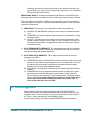
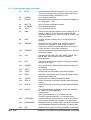
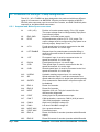
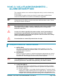
CONTACTOR OPEN
The main contactor coil has been driven by the logic board (NMC has
become low), but the contactor does not close. Any function is prevented.
Two possible reasons:
A) the MC coil is damaged or it is rated to a voltage larger than the
voltage applied. Check the coil.
B) the two contacts of the contactor are not properly working, and they
cannot close. Check them.
- CONTACTOR CLOSED
AT start-up the controller checks if the MC contact is already closed
when the coil isn’t driven yet. The test is carried out by trying to discharge
the capacitor bank. If they don’t discharge, the failure condition is entered
and any function is prevented.
It is suggested to check the contactor contacts, in particular if they are
mechanically stuck or pasted.
Notice that this test isn’t carried out if, at start-up, the capacitor are
completely discharged.
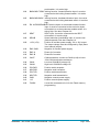
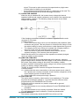
AUX OUTPUT KO
The controller checks the driver inside the NEB pin. If the status of the driver
output does not correspond to the signal coming from the microcontroller, this
alarm is signalled, MC opens and all function are stopped.
Possible causes are:
o Presence of external shorts or misconnections. Check the EB coil
wire.
o There is an internal failure. Replace the controller.
COIL SHORTED
Inside the logic board there is a shunt in common with both the NMC and the
NEB output drivers. This shunt is used to detect overcurrent conditions in
these outputs: in case of an overcurrent event the NMC and ENB drivers are
stopped and this alarm is raised. Look for short circuit in parallel with the MC
and EB coils or if these coils have the correct impedance. If no short is
present and the alarm persists, the failure is internal to the controller, which
must be replaced.
The overcurrent detection circuit is checked at start-up too. If this test fails,
the alarm is raised. In this case, the failure is only internal to the logic board
and the controller must be replaced.
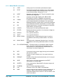
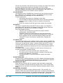
HIGH TEMPERATURE
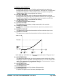
This is a warning and not an alarm. It indicates that the controller
temperature is greater than 75 °C. The maximum current is reduced
proportionally to the temperature increase. The controller current drops to
zero at 100 °C.
If the alarm is signalled when the controller is cold there is an internal failure
and the controller must be replaced.
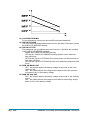
MOTOR TEMPERATURE
This warning is signalled if the motor temperature switch opens (digital
sensor) or if the analog signal overtakes the cut off level (defined by
ADJUSTMENT #4 parameter). The motor current is reduced to avoid any
damage to the motor. If it happens when the motor is cold, check the wiring.
If the wires are ok, replace the controller.
THERMIC SENSOR KO
The range of internal temperature sensor is always checked and a warning is
signalled if it is out of range. When this happens, the motor current is
reduced to half its max value.
This is an internal failure: replace the controller.
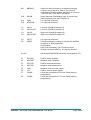
MOT. TH. SENSOR KO
ADWZP0DF - AC3 FLASH / AC4 FLASH INVERTER - User Manual
Page - 81/89